

Philips Medical Systems North America WLANBV3 Users Manual

Instructions for Use
IntelliVue Patient Monitor
MP2
Release L with Software Revision L.xx.xx
Patient Monitoring


1Table of Contents
1 Basic Operation 11
Safety Information 12
Security Information 13
Introducing the IntelliVue MP2 15
Controls, Indicators and Connectors 15
Extending Measurements 17
Operating and Navigating 22
Operating Modes 27
Understanding Screens 29
Using the XDS Remote Display 29
Using the Visitor Screen 30
Understanding Profiles 30
Understanding Settings 31
Changing Measurement Settings 32
Switching a Measurement On and Off 32
Adjusting a Measurement Wave 32
Using Labels 33
Using IntelliVue Cableless Measurements 35
Changing Monitor Settings 37
Checking Your Monitor Revision 37
Getting Started 37
Disconnecting from AC Mains Power 39
Monitoring After a Power Failure 39
Networked Monitoring 40
Capturing Alarm Reports and Printing 40
2 What's New? 41
What's New in Release L 41
What's New in Release K.2 42
What's New in Release J.0 42
What's New in Release H.0 44
What's New in Release G.0? 44
What's New in Release F.0? 45
3 Alarms 47
Visual Alarm Indicators 48
Audible Alarm Indicators 49
Acknowledging Alarms 51
Pausing or Switching Off Alarms 51
Alarm Limits 54
3

Reviewing Alarms 57
Latching Alarms 58
Testing Alarms 59
Alarm Behavior at Power On 59
Alarm Recordings 60
4 Patient Alarms and INOPs 61
Patient Alarm Messages 61
Technical Alarm Messages (INOPs) 68
5 Managing Patients and Equipment 85
Patient Concepts 85
Equipment Concepts 85
Managing Patients 86
Transferring Patients 91
Managing Equipment 95
Information Center Compatibility 103
6 ECG, Arrhythmia, ST and QT Monitoring 105
Skin Preparation for Electrode Placement 105
Connecting ECG Cables 105
Selecting the Primary and Secondary ECG Leads 106
Checking Paced Mode 106
Understanding the ECG Display 107
Monitoring Paced Patients 108
Changing the Size of the ECG Wave 109
Changing the Volume of the QRS Tone 110
Changing the ECG Filter Settings 110
Choosing EASI or Standard Lead Placement 110
Selecting Positions of Va and Vb Chest Leads (for 6-lead placement) 111
About ECG Leads 111
ECG Lead Fallback 112
ECG Lead Placements 112
Capture 12-Lead 118
EASI ECG Lead Placement 122
ECG and Arrhythmia Alarm Overview 123
Using ECG Alarms 125
ECG Safety Information 127
About Arrhythmia Monitoring 129
Switching Arrhythmia Analysis On and Off 129
Choosing an ECG Lead for Arrhythmia Monitoring 129
Understanding the Arrhythmia Display 131
Arrhythmia Relearning 134
Arrhythmia Alarms 135
About ST Monitoring 139
Switching ST or STE On and Off 140
4

Understanding the ST Display and Windows 141
Updating ST Baseline Snippets 143
About the ST Measurement Points 143
ST Alarms 146
STE Alarms 147
Viewing ST Maps 147
About QT/QTc Interval Monitoring 152
QT Alarms 155
Switching QT Monitoring On and Off 156
7 Monitoring Pulse Rate 157
Entering the Setup Pulse Menu 157
System Pulse Source 157
Switching Pulse On and Off 158
Using Pulse Alarms 158
8 Monitoring Respiration Rate (Resp) 161
Lead Placement for Monitoring Resp 161
Understanding the Resp Display 162
Changing Resp Detection Modes 163
Changing the Size of the Respiration Wave 164
Changing the Speed of the Respiration Wave 164
Using Resp Alarms 164
Changing the Apnea Alarm Delay 164
Resp Safety Information 164
9 Monitoring with the CL Respiration Pod (cmResp) 167
Measurement Principles 167
Measurement Modes 168
Making Measurements 168
Understanding the Numerics 168
Setting the Measurement Mode 169
Setting the Repeat Time 169
Switching Posture and Activity Level On and Off 170
10 Monitoring SpO2 171
SpO2 Sensors 171
Applying the Sensor 172
Connecting SpO2 Cables 173
Measuring SpO2 173
Understanding the SpO2 Numerics 174
Assessing a Suspicious SpO2 Reading 175
Changing the Averaging Time 175
Setting the Measurement Mode 176
Understanding SpO2 Alarms 176
Pleth Wave 181
5

Perfusion Numeric 181
Perfusion Change Indicator 181
Setting SpO2/Pleth as Pulse Source 181
Setting Up Tone Modulation 182
Setting the QRS Volume 182
11 Monitoring NBP 183
Introducing the Oscillometric NBP Measurement 183
Preparing to Measure NBP 185
Starting and Stopping Measurements 187
Enabling Automatic Mode and Setting Repetition Time 188
Enabling Sequence Mode and Setting Up The Sequence 189
Choosing the NBP Alarm Source 189
Switching Pulse from NBP On/Off 190
Assisting Venous Puncture 190
Calibrating NBP 190
12 Monitoring Temperature 191
Making a Temp Measurement 191
Calculating Temp Difference 192
13 Monitoring Invasive Pressure 193
Setting up the Pressure Measurement 193
Overview of Calibration Procedures 195
Zeroing the Pressure Transducer 195
Calibrating Reusable Transducers 197
Adjusting the Calibration Factor 199
Displaying a Mean Pressure Value Only 199
Changing the Pressure Wave Scale 199
Optimizing the Waveform 199
Non-Physiological Artifact Suppression 199
Choosing the Pressure Alarm Source 200
Calculating Cerebral Perfusion Pressure 201
14 Monitoring Carbon Dioxide 203
Measurement Principles 204
Measuring CO2 using the CO2 Option or M3014A 205
Measuring Microstream CO2 using M3015A/B 209
Setting up all CO2 Measurements 210
Understanding the IPI Numeric 213
15 Using a Telemetry Device and a Monitor 215
How Can You Combine Devices? 215
Unpairing the Monitor and Telemetry Device 218
Temporarily Stopping the Short Range Radio Connection 218
6

16 Enhancing Telemetry Monitoring with the Monitor 219
Monitor and Telemetry Transceiver Requirements 219
17 Trends 221
Viewing Trends 221
Setting Up Trends 224
Documenting Trends 227
Trends Databases 227
Screen Trends 228
18 Recording 231
Starting and Stopping Recordings 231
Overview of Recording Types 232
Creating and Changing Recordings Templates 232
Recorder Status Messages 233
19 Printing Patient Reports 235
Starting Report Printouts 235
Stopping Reports Printouts 236
Setting Up Reports 236
Setting Up Individual Print Jobs 238
Checking Printer Settings 238
Printing a Test Report 239
Switching Printers On or Off for Reports 239
Dashed Lines on Reports 239
Unavailable Printer: Re-routing Reports 239
Checking Report Status and Printing Manually 240
Printer Status Messages 241
Sample Report Printouts 242
20 Care and Cleaning 245
General Points 245
Cleaning the Monitor 246
Disinfecting the Equipment 246
Sterilizing the Equipment 247
Cleaning, Sterilizing and Disinfecting Monitoring Accessories 247
Cleaning Batteries and the Battery Compartment 247
21 Using Batteries 249
Battery Power Indicators 250
Checking Battery Charge 252
When Battery Lifetime is Expired 252
Replacing a Battery 253
Optimizing Battery Performance 254
Battery Safety Information 256
7

22 Maintenance and Troubleshooting 257
Inspecting the Equipment and Accessories 257
Inspecting the Cables and Cords 258
Maintenance Task and Test Schedule 258
Troubleshooting 258
Disposing of the Monitor 259
Disposing of Empty Calibration Gas Cylinders 259
23 Accessories 261
ECG/Resp Accessories 261
NBP Accessories 264
Invasive Pressure Accessories 270
SpO2 Accessories 273
Temperature Accessories 278
Mainstream CO2 Accessories 279
Sidestream CO2 Accessories 279
Microstream CO2 Accessories 280
Battery Accessories 281
24 Specifications 283
Indications for Use 283
Use Environment 283
Restricted Availability 284
Manufacturer's Information 284
Symbols 285
Installation Safety Information 287
Monitor Mounting Precautions 287
Altitude Setting 288
Monitor Safety Specifications 288
EMC and Radio Regulatory Compliance 288
Out-Of-Hospital Transport - Standards Compliance 290
Physical Specifications 291
Environmental Specifications 292
Monitor Performance Specifications 293
Monitor Interface Specifications 294
865297 Battery Extension Specifications 296
M4607A Battery Specifications 296
M4605A Battery Specifications 297
Measurement Specifications 298
Safety and Performance Tests 312
25 Default Settings Appendix 317
Alarm and Measurement Default Settings 317
Alarm Default Settings 317
ECG, Arrhythmia, ST and QT Default Settings 318
Pulse Default Settings 321
8

Respiration Default Settings 321
SpO2 Default Settings 322
NBP Default Settings 322
Temperature Default Settings 323
Invasive Pressure Default Settings 323
CO2 Default Settings 325
Index 327
9

10

1Basic Operation
These Instructions for Use are for clinical professionals using the IntelliVue MP2 (M8102A) patient
monitor.
This basic operation section gives you an overview of the monitor and its functions. It tells you how to
perform tasks that are common to all measurements (such as entering data, switching a measurement
on and off, setting up and adjusting wave speeds, working with profiles). The alarms section gives an
overview of alarms. The remaining sections tell you how to perform individual measurements, and
how to care for and maintain the equipment.
Familiarize yourself with all instructions including warnings and cautions before starting to monitor
patients. Read and keep the Instructions for Use that come with any accessories, as these contain
important information about care and cleaning that is not repeated here.
This guide describes all features and options. Your monitor may not have all of them; they are not all
available in all geographies. Your monitor is highly configurable. What you see on the screen, how the
menus appear and so forth, depends on the way it has been tailored for your hospital and may not be
exactly as shown here.
1
This guide may contain descriptions of functionality and features that are not implemented in the
equipment currently shipped to Japan and/or of products that are not currently sold in Japan due to
limitations and restrictions under the applicable local laws and regulations in Japan. Contact your local
sales representative and/or Philips Customer Support for details.
In this guide:
•A warning alerts you to a potential serious outcome, adverse event or safety hazard. Failure to
observe a warning may result in death or serious injury to the user or patient.
•A caution alerts you to where special care is necessary for the safe and effective use of the
product. Failure to observe a caution may result in minor or moderate personal injury or damage
to the product or other property, and possibly in a remote risk of more serious injury.
• Monitor refers to the entire patient monitor. Display refers to the physical display unit. Screen
refers to everything you see on the monitor's display, such as measurements, alarms, patient data
and so forth.
For installation, repair, testing and troubleshooting instructions, refer to the Service Guide for your
monitor model.
Rx only: U.S. Federal Law restricts this device to sale by or on the order of a physician.
11

1 Basic Operation
Safety Information
The following warnings apply to the monitors in general. Warnings that apply to specific
measurements or procedures can be found in the corresponding chapters.
Electrical Hazards and Interference
WARNING
Grounding: To avoid the risk of electric shock, the monitor must be grounded during operation. If a
three-wire receptacle is not available, consult the hospital electrician. Never use a three-wire to twowire adapter.
Electrical shock hazard: Do not open the monitor or measurement device. Contact with exposed
electrical components may cause electrical shock. Refer servicing to qualified service personnel.
Leakage currents: If multiple instruments are connected to a patient, the sum of the leakage currents
may exceed the limits given in:
• IEC/EN 60601-1
• ANSI/AAMI ES60601-1
• CAN/CSA C22.2 No. 60601-1-08
Consult your service personnel.
Radio frequency interference: The monitor generates, uses and radiates radio-frequency energy, and
if it is not installed and used in accordance with its accompanying documentation, may cause
interference to radio communications.
Use Environment
WARNING
Explosion Hazard: Do not use in the presence of flammable anesthetics or gases, such as a
flammable anesthetic mixture with air, oxygen or nitrous oxide or in the presence of other flammable
substances in combination with air, oxygen-enriched environments, or nitrous oxide. Use of the
devices in such environments may present an explosion hazard.
Positioning Equipment: The monitor should not be used next to or stacked with other equipment.
If you must stack the monitor, check that normal operation is possible in the necessary configuration
before you start monitoring patients.
Environmental Specifications: The performance specifications for the monitors, measurements and
accessories apply only for use within the temperature, humidity and altitude ranges specified in the
environmental specifications in the Instructions for Use.
12
Liquid Ingress: If you spill liquid on the equipment, battery, or accessories, or they are accidentally
immersed in liquid, contact your service personnel or Philips service engineer. Do not operate the
equipment before it has been tested and approved for further use.
Prohibited Environments: The monitors are not intended for use in an MRI environment or in an
oxygen-enriched environment (for example, hyperbaric chambers).

Alarms
WARNING
• Do not rely exclusively on the audible alarm system for patient monitoring. Adjustment of alarm
• Be aware that the monitors in your care area may each have different alarm settings, to suit
Accessories
WARNING
Philips' approval: Use only Philips-approved accessories. Using other accessories may compromise
device functionality and system performance and cause a potential hazard.
Reuse: Never reuse disposable transducers, sensors, accessories and so forth that are intended for
single use, or single patient use only. Reuse may compromise device functionality and system
performance and cause a potential cross-infection hazard.
1 Basic Operation
volume to a low level or off during patient monitoring may result in patient danger. Remember
that the most reliable method of patient monitoring combines close personal surveillance with
correct operation of monitoring equipment.
different patients. Always check that the alarm settings are appropriate for your patient before you
start monitoring.
Electromagnetic compatibility: Using accessories other than those specified may result in increased
electromagnetic emission or decreased electromagnetic immunity of the monitoring equipment.
Damage: Do not use a damaged sensor or one with exposed electrical contacts. Do not use damaged
accessories. Do not use accessories where the packaging has been damaged or opened.
Cables and tubing: Always position cables and tubing carefully to avoid entanglement or potential
strangulation.
MR Imaging: During MR imaging, remove all transducers, sensors and cables from the patient.
Induced currents could cause burns.
Use-by date: Do not use accessories where the use-by date has been exceeded.
Electrosurgery: Do not use antistatic or conductive endotracheal tubes as they may cause burns in
case of electrosurgery.
Security Information
Protecting Personal Information
Protecting personal health information is a primary component of a security strategy. Each facility
using the monitors must provide the protective means necessary to safeguard personal information
consistent with country laws and regulations, and consistent with the facility’s policies for managing
this information. Protection can only be realized if you implement a comprehensive, multi-layered
strategy (including policies, processes, and technologies) to protect information and systems from
external and internal threats.
13

1 Basic Operation
As per its intended use, the patient monitor operates in the patient vicinity and contains personal and
sensitive patient data. It also includes controls to allow you to adapt the monitor to the patient's care
model.
To ensure the patient's safety and protect their personal health information you need a security
concept that includes:
• Physical security access measures - access to the monitor must be limited to authorized users.
• Operational security measures - for example, ensuring that patients are discharged after
• Procedural security measures - for example, assigning only staff with a specific role the right to
In addition, any security concept must consider the requirements of local country laws and regulations.
Always consider data security aspects of the network topology and configuration when connecting
patient monitors to shared networks. Your medical facility is responsible for the security of the
network, where sensitive patient data from the monitor may be transferred.
When a monitor is returned for repair, disposed of, or removed from your medical facility for other
reasons, always ensure that all patient data is removed from the monitor by ending monitoring for the
last patient (see “Ending Monitoring for a Patient” on page 89).
It is essential that you consider physical security measures to ensure that unauthorized users
cannot gain access.
monitoring in order to remove their data from the monitor.
use the monitors.
NOTE
Log files generated by the monitors and measurement modules are used for system troubleshooting
and do not contain protected health data.
About HIPAA Rules
If applicable, your facility’s security strategy should include the standards set forth in the Health
Insurance Portability and Accountability Act of 1996 (HIPAA), introduced by the United States
Department of Health and Human Services. You should consider both the security and the privacy
rules and the HITECH Act when designing policies and procedures. For more information, please
visit:
http://www.hhs.gov/ocr/privacy/.
About the EU Directives
If applicable, your facility’s security strategy should include the practices set forth in the Directive on
the protection of individuals with regard to the processing of personal data and on the free movement
of such data (Directive 95/46/EC of the European Parliament and of the Council of
24 October 1995). In addition, your facility should also take into account any additional, more
stringent standards put forward by any individual EU countries; that is, Germany, France, and so on.
Philips Product Security Policy Statement
Additional security and privacy information can be found on the Philips product security web site at:
http://www.healthcare.philips.com/main/support/equipment-performance/product-security/
index.wpd
14

1 Basic Operation
Manufacturer Disclosure Statement for Medical Device Security – MDS2
You can view the Manufacturer Disclosure Statements for Medical Device Security (MDS2) for
specific devices at:
http://www.healthcare.philips.com/main/support/equipment-performance/product-security/
index.wpd
Introducing the IntelliVue MP2
The Philips IntelliVue MP2 monitor provides a comprehensive set of basic physiological
measurements: ECG (including ST analysis and optional 10-lead ECG), NBP, SpO
invasive blood pressure, temperature and CO
integration, documentation and information access. The MP2 can be used with adult, pediatric and
neonatal patients in a hospital environment and during patient transport both inside and outside
hospitals.
The monitor stores data in trend databases. You can see tabular trends (vital signs) and document
them on a central printer. You can view measurement trend graphs, including horizon trends, to help
you identify changes in the patient's physiological condition.
. Through networking it provides information
2
, and optionally
2
The monitor can be powered by a rechargeable battery, or from AC mains using the external power
supply (M8023A). For battery charging, care and status information, refer to the chapter “Using
Batteries” on page 249.
Controls, Indicators and Connectors
MP2 Overview
1 On/Standby Switch
2 Power and battery indicators (see “MP2 Controls and Indicators” on page 16)
3 3.5-inch TFT LCD touchscreen QVGA display
15

1 Basic Operation
Alarm lamps (see “MP2 Controls and Indicators” on page 16)
4
5 Built-in carrying handle
6 Battery eject button
7 Keys (see “MP2 Controls and Indicators” on page 16)
8 Measurement connectors (see “MP2 Patient Connectors, Right Side” on page 17)
9 Battery
MP2 Controls and Indicators
1 On/Standby switch
2 On/Standby LED. Green when monitor is on. Red indicates an error.
3 Battery status LED. Yellow when charging. Flashing red when battery is empty, or a battery
malfunction is detected.
4 External power LED. Green when monitor is powered from an external power source.
5 Alarms off indicator. When alarms are suspended, the lamp is red, and the Alarms Off message
appears on the screen.
6 Active INOP alarm lamp in light blue. Stays lit until active INOP is acknowledged.
7 Active alarm lamp. Red or yellow, depending on alarm level. Stays lit until active alarm is
acknowledged.
8 Silence key
9 Alarms key: turns alarms On/Off, or pauses them
10 SmartKeys key: brings up SmartKeys on the screen
11 Main Screen key: closes all open menus/windows and returns to the main screen, or selects
current screen.
16

MP2 Patient Connectors, Right Side
English version International version
1 Basic Operation
1 Pressure (option)
2 Temperature (option)
3 Noninvasive blood pressure
MP2 Left Side
4 SpO
5 ECG sync pulse output (See
6 ECG/Respiration
7 CO
1 Loudspeaker (do not cover with labels or stickers as this
will reduce the loudspeaker volume).
2 MSL Connector. Connects to the external power supply via
the MSL cable for AC mains operation, battery charging,
and communication with a network.
2
“Monitor Performance
Specifications” on page 293 for
specifications)
(option)
2
Extending Measurements
Your monitor is compatible with Philips measurement extensions for use with other IntelliVue patient
monitoring devices. These allow you to add specific measurements to those already integrated into
your monitor. These measurement extensions are referred to as MMS extensions. During patient
transport, the monitor with the connected MMS extension can be powered by the Battery Extension
(see “Using the Battery Extension” on page 20).
17

1 Basic Operation
MMS Extension M3014A attached to the MP2
The MMS extensions connect to the monitor and use the monitor's settings. Trend data and
measurement settings from the measurements in the extensions are stored in the monitor.
WARNING
• Measurements from an MMS extension are only available when the extension is connected to the
monitor, and the monitor is running on external power. This is the case when the monitor is
running on AC mains via the external power supply (M8023A) or is attached to the Battery
Extension (865297). Measurements from an MMS extension connected to the monitor are not
available when the monitor is running on its own battery power.
• Any measurements on an MMS extension that conflict with those in the monitor cannot be used.
For example, only one CO
measurement is supported.
2
• The Cardiac Output and Continuous Cardiac Output option of the MMS extensions is not
available for the MP2 monitor.
To separate an extension from the monitor, press the release lever and push the extension forward.
18

1 Basic Operation
M3014A, M3015A, and M3015B Capnography MMS Extensions
The optional M3014A Capnography extension adds mainstream capnography or sidestream
capnography, and optionally one pressure plus either a pressure or a temperature to the monitor.
M3014A
1 Pressure connectors (red)
2 Temperature connector (brown)
3 Mainstream/sidestream connector CO
4 Cardiac Output connector
The optional M3015A Microstream CO
extension adds microstream capnography and optionally
2
either pressure or temperature to the monitor. The optional M3015B Microstream CO
adds microstream capnography, two pressures and a temperature to the monitor.
M3015A M3015B
2
extension
2
1 Pressure connectors (red) - M3015A optional
2 Temperature connector (brown) - M3015A optional
3 Gas sample outlet
4 Microstream connector CO
and Inlet
2
19

1 Basic Operation
M3012A Hemodynamic MMS Extension
1 Cardiac Output (orange; optional)
2 Connection to monitor
3 Pressure connectors (red)
4 Temperature connectors (brown)
When attached to the MP2 connected to the external power supply, the optional M3012A
Hemodynamic extension adds temperature, pressure, and an additional pressure or a temperature to
the monitor.
Using the Battery Extension
To provide enough power for the use of an MMS Extension during transport, you can use the Battery
Extension (865297). The Battery Extension provides additional battery power for situations when no
mains power is available and can typically power the monitor with MMS Extension for at least 6 hours.
When running from the Battery Extension with no mains supply available, the monitor will not charge
its internal battery.
Connecting the Battery Extension
To connect to the Battery Extension, place the
monitor with MMS Extension onto the Battery
Extension, and then slide it across so that the
connection is made and it is firmly seated.
20

LED Indicators
The Battery Extension has two LED indicators. The power LED lights green when the Battery
Extension is connected to external power.
1 Basic Operation
To remove the monitor with MMS Extension,
press the release lever and push the monitor
across to release the connection.
The battery charge led gives battery status information.
External power available
LED indication Status
green Battery fully charged.
yellow Battery charging.
red flashing (short on phase) Battery maintenance required.
red flashing (long on phase) Battery Extension malfunction.
off No battery inserted in the Battery Extension.
External power not available
LED indication Status
yellow flashing (short on phase) Battery Extension is charging the monitor battery (monitor is
switched off).
red flashing (short on-phase) If the monitor is running, this indicates very low battery charge
(<10 minutes running time left). If the monitor is not running,
this indicates that battery maintenance is required.
red flashing (long on-phase) Battery Extension cannot provide power to the monitor.
Either the Battery Extension needs charging, or it has a
malfunction.
21

1 Basic Operation
IntelliVue Cableless Measurements
The IntelliVue Cableless Measurements (IntelliVue CL SpO2 Pod CL NBP Pod and CL Respiration
Pod) are patient-worn measurement devices which communicate measurement values to the monitor
using a wireless short range radio (SRR) interface. The CL SpO
measurement values on their built-in screen.
Measurement Device Main Parts and Keys
The SpO2 Pod and the NBP Pod have an LCD display and three keys for basic operation e.g. to assign
the device to a patient:
1 Integrated monochrome LCD display
2 Hardkeys
3 Measurement identifier
Pod and CL NBP also provide the
2
The Respiration Pod has one multi-color LED for status display and one hardkey for basic operation,
e.g. to start a measurement:
1 Multi-color LED
2 Hardkey
3 Indication for built-in RFID tag
Operating and Navigating
The principle method of operating your monitor is via the touchscreen. Almost every element on the
screen is interactive. Screen elements include measurement numerics, information fields, alarms fields,
waveforms and menus. The typical operator's position is in front of the monitor.
There are also four keys to the right of the screen (see also “MP2 Controls and Indicators” on
page 16).
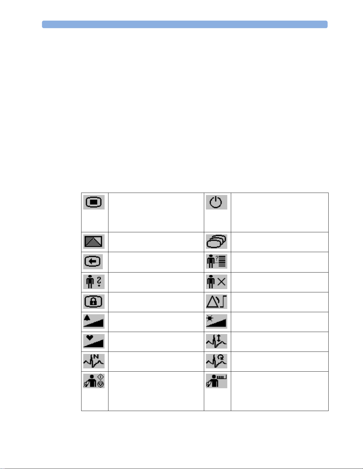
These let you: Key with symbol
• Silence alarms: the Silence key acknowledges all active
alarms by switching off audible alarm indicators and
lamps.
• Switch alarms on or off, or pause alarms.
(international)
Text replaces
symbol (English
versions only)
22
1 Basic Operation
These let you: Key with symbol
(international)
• Call up SmartKeys on the screen (see below).
• Close all open menus/windows and return to the main
screen.
• If you are already in the main screen (no additional
menus/windows are open), then pressing this key opens
Change Screen menu, where you can choose from a
the
number of pre-configured screens.
• To temporarily disable the touchscreen operation, press
and hold this key for 2 seconds. Press the key again to reenable the touchscreen operation.
A typical main screen looks like this:
Text replaces
symbol (English
versions only)
MP2 Screen Elements
Item Description Comments
1 Alarm volume off indicator
is displayed when the alarm volume is set to zero
(0).
23

1 Basic Operation
MP2 Screen Elements
Item Description Comments
2 Patient name / alarm
message field
3 Patient category and bed label
/ INOP message field
4 Network connection
indicator
5 Measurement label Touch the measurement to enter the measurement setup
6 Paced status Displayed below the HR label.
7 Measurement numeric/values Touch the numeric to enter the measurement setup menu.
8 Measurement wave Touch the wave to enter the measurement setup menu.
9 Status line Shows information and messages prompting you for
10 Measurement Selection key Opens the
11 Battery status indicator Gives information about remaining battery charge,
Patient name can be covered by alarm messages or alarms
On/Off/Paused message.
If red and yellow alarms are active at the same time, they
rotate in the alarm field.
Patient category and bed label can be covered by INOP
messages. If there are multiple red/yellow/cyan INOPs
active at the same time, they rotate in the INOP field.
Documented in Information Center Instructions for Use.
menu.
action.
Measurement Selection window which shows all
measurements and where they are physically located. From
here you can also enter the measurement setups.
estimated operating time, maintenance requirements and
malfunctions. See the chapter “Using Batteries” on
page 249.
Using the Touchscreen
Touch a screen element to get to the actions linked to that element. For example, touch a
measurement numeric and the setup menu for that measurement opens. Touch a wave to enter the
setup menu for that wave.
Measurement Setup Menus
Each measurement has a setup menu where you can change settings. Typically, the setup menu
window covers the whole screen, except the INOP and alarm message fields, which are always
displayed at the top. The following picture is an example, and may not show exactly what you see on
the screen. All measurement setup windows are similar and share the same basic layout.
24

Touch the measurement numeric on the screen to enter the setup menu.
Key to measurement setup menu:
Item Description Comment
1 Basic Operation
1 INOP and alarm
message field
2 Wave/numerics
window
3 Status/prompt
message
4 Next page arrows The menu may have more than one page, as shown here. Move to
5 Measurement menu
keys
Main Setup Menu
There is usually more than one way to enter a setup menu for a measurement, to change a setting or to
execute a task. Some routes are more direct than others. You can use whichever method you find most
convenient. Which routes are available to you, however, can vary depending on your monitor’s
configuration.
These are always displayed at the top of the screen.
The main measurement numeric and wave (if applicable) are shown
in this window so that you do not lose sight of the current
measurement while making changes in the menu.
Status/prompt messages related to the measurement menu are
displayed below the wave/numerics. General status/prompt
messages on the main screen are covered by the measurement setup
menu.
another page by touching these arrows.
Each button has two lines of text. To perform an operation on a
measurement, press one of the keys. Some keys lead directly to a
task. For example, pressing the
Start/ Stop key for noninvasive blood
pressure starts a measurement. Other keys open a pop-up window,
which can have more than one page, from which you make a
selection. Again, using noninvasive blood pressure as an example,
pressing the
Repeat Time key for setting the repetition time opens a
pop-up window from which you pick a time, scrolling if necessary.
For this reason, this book generally describes entry to a measurement’s setup menu via the
Main Setup
menu, as this route is always available and is not subject to configuration dependencies. You can get to
all setup windows from the
SmartKeys key, then selecting the
Main Setup menu. You enter the Main Setup menu by pressing the
Main Setup SmartKey.
25
1 Basic Operation
SmartKeys
A SmartKey is a configurable graphical key on the screen allowing fast access to frequently used
functions. Press the SmartKeys hard key to call up a set of SmartKeys on the screen. Although the
selection of SmartKeys available on your monitor depends on the monitor configuration and on the
options purchased, the
SmartKeys window generally looks like this:
1 Scroll to see more SmartKeys
enter Main Setup menu - you can get
to all setup windows using this key
enter profile menu, or
revert to default profile
previous Screen quick admit a patient
enter patient identification menu to
admit/discharge/transfer
lock touchscreen operation set alarm limits
change alarm volume change screen brightness (not for
change QRS volume change amplitude (size) of ECG wave
review beat labels (annotate
arrhythmia wave)
enter standby mode - suspends patient
monitoring. All waves and numerics
disappear from the display. All settings
and patient data information are
retained.
change Screen, or
revert to default screen
end case to discharge a patient
independent displays)
re-learn arrhythmia
26
- start/stop manual NBP
measurement
- start auto series
- stop current automatic measurement
within series
start NBP STAT measurement
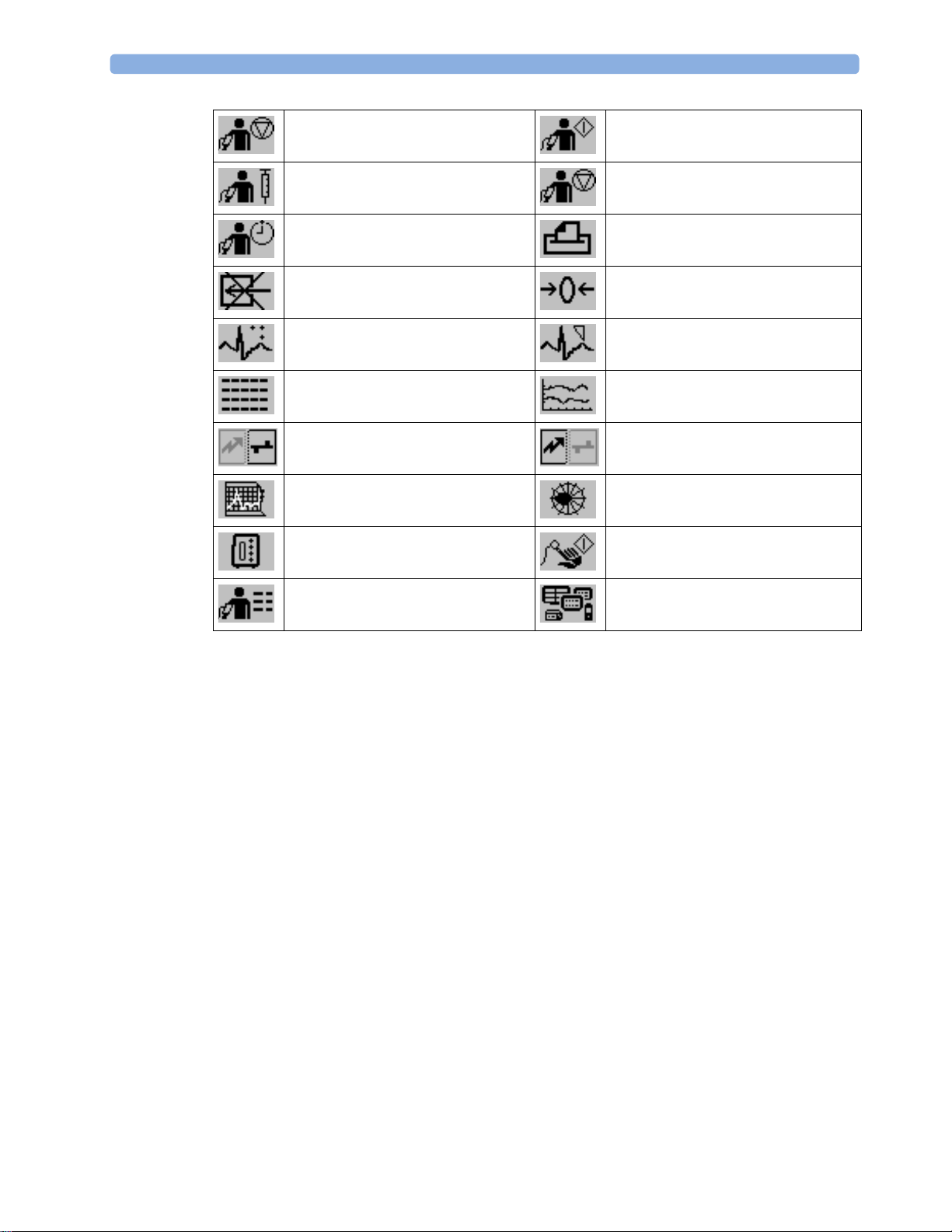
1 Basic Operation
stop automatic or STAT NBP
measurement and measurement series
start veni puncture (inflate cuff to
subdiastolic pressure)
set the NBP repeat time access patient reports
switch CO
new lead setup set standard or EASI lead placement
review vital signs trend review graph trend
unpair equipment and continue central
monitoring with the monitor
start 12-Lead Capture (only available if
Information Center is connected)
select measurement device start an SpO
pump off zero invasive pressure transducer
2
start NBP measurement and
measurement series
stop current NBP measurement
unpair equipment and continue central
monitoring with the telemetry device
access ST Map application
measurement
2
access NBP mode selection and setup,
with direct start/stop function
Pop-Up Keys
Pop-up keys are task-related graphical keys that appear automatically on the monitor screen when
required. For example, the
Confirm pop-up key appears only when you need to confirm a change.
Using the On-Screen Keyboard
Use this as you would a conventional keyboard. Enter the information by selecting one character after
another. Use the
characters, or use the
close the on-screen keyboard.
Shift and capital Lock keys to access uppercase letters. Use the Back key to delete single
Clr key to delete entire entries. Select Enter to confirm what you have entered and
Operating Modes
When you switch the monitor on, it starts up in monitoring mode. To change to a different mode:
1 Select the Main Setup menu.
2 Select Operating Modes and choose the mode you require.
open the
Equipment window
27

1 Basic Operation
Your monitor has four operating modes. Some are passcode protected.
• Monitoring Mode: This is the normal, every day working mode that you use for monitoring
• Demonstration Mode: Passcode protected, this is for demonstration purposes only. You must
• Configuration Mode: Passcode protected, this mode is for personnel trained in configuration
• Service Mode: Passcode protected, this is for trained service personnel.
When the monitor is in Demonstration Mode, Configuration Mode, or Service Mode, this is indicated
by a box with the mode name in the center of the Screen and a symbol in the bottom right-hand
corner. Select the mode box in the center of the screen to change to a different mode.
patients. You can change elements such as alarm limits, patient category and so forth. When you
discharge the patient, these elements return to their default values. Changes can be stored
permanently only in Configuration Mode. You may see items, such as some menu options or the
altitude setting, that are visible but ‘grayed out’ so that you can neither select nor change them.
These are for your information and can be changed only in Configuration Mode.
not change into Demonstration Mode during monitoring. In Demonstration Mode, all stored
trend information is deleted from the monitor’s memory.
tasks. These tasks are described in the Configuration Guide. During installation the monitor is
configured for use in your environment. This configuration defines the default settings you work
with when you switch on, the number of waves you see and so forth.
Standby Mode
Standby mode can be used when you want to temporarily interrupt monitoring.
To enter Standby mode,
1 Press the SmartKeys key .
2 Either select the Monitor Standby SmartKey
Or select the
The Standby screen is a neutral screen with information about the monitor and instructions on how to
leave Standby mode.
The monitor enters Standby mode automatically after the End Case function is used to discharge a
patient. Standby suspends patient monitoring. All waves and numerics disappear from the display but
all settings and patient data information are retained. The Standby screen is displayed.
If a temporary patient location has been entered at the monitor or at the Information Center, this
location will also be displayed on the Standby screen.
To resume monitoring,
• Select anything on the screen or press any key.
When monitoring is resumed, alarms are paused for 1 minute to allow time to finish plugging in the
measurement cables.
Main Setup SmartKey, then select Monitor Standby.
28

Understanding Screens
Your monitor comes with a set of pre-configured Screens, optimized for common monitoring
scenarios such as "OR adult", or "ICU neonatal". A Screen defines the overall selection, size and
position of waves, numerics and other elements on the monitor screen when you switch on. You can
easily switch between different Screens during monitoring. Screens do NOT affect alarm settings,
patient category and so forth.
Switching to a Different Screen
To switch to a different Screen:
1 After closing any open menus or windows, press the Main Screen key to access the Change Screen
menu.
2 Choose the new Screen from the Change Screen menu.
Changing a Screen’s Content
If you do not want to change the entire Screen content, but only some parts of it, you can substitute
individual waves, numerics, or trends. Be aware that these changes cannot be stored permanently in
Monitoring Mode.
1 Basic Operation
To change the selection of elements on a Screen,
1 Select the element you want to change. For example, touch the wave to enter the wave setup menu,
or touch the numeric to enter the numeric setup menu.
2 From the menu that appears, select Change Wave or Change Numeric, and then select the wave or
numeric you want.
In the
Change Screen menu, the changed Screen is shown linked to the original Screen and marked with
an asterisk.
Up to three modified Screens can be accessed via the
To recall Screens, select the name of the Screen in the
After a patient discharge, the monitor’s default Screen is shown. Modified Screens are still available in
Change Screen menu.
the
If the monitor is switched off and then on again, modified Screens are erased from the monitor’s
memory and cannot be recalled. If a modified Screen was the last active Screen when the monitor was
switched off, it is retained unless the monitor is configured to revert to the default.
Change Screen menu.
Using the XDS Remote Display
Using the IntelliVue XDS Solution it is possible to view an independent monitor screen on an external
display. The XDS Solution consists of a medical grade PC-based hardware platform, XDS Application
software and the XDS connectivity option on the monitor. Depending on the configuration you can
also operate the monitor from the external display. The XDS must be connected to the same Local
Area Network (LAN) as the monitor.
Change Screen menu.
It is also possible to use an existing PC, connected to the same LAN, to host the XDS Application
software.
For more details, including limitations and restrictions, refer to the IntelliVue XDS Application
Instructions for Use.
29

1 Basic Operation
Using the Visitor Screen
If a visitor Screen is configured for your monitor, you can use it to clear the screen of all waves and
numerics but continue to monitor the patient with active alarms and trend storage at the bedside and
Information Center. When the visitor Screen is selected, no automatic pop-up windows will be
displayed. You can change the name of the visitor Screen in Configuration Mode.
To activate this Screen,
1 Press the Main Screen key to open the Change Screen menu.
2 Select the name of the visitor Screen configured for your monitor from the list of available
Screens.
To select a Screen with waves and numerics again,
• Touch the gray box in the center of the screen showing the visitor Screen's name, or press the
Main Screen key, to open the
Change Screen menu and then select a Screen from the list.
Understanding Profiles
Profiles are predefined monitor configurations. They let you change the configuration of the whole
monitor so you can adapt it to different monitoring situations. The changes that occur when you
change a complete profile are more far reaching than those made when you change a Screen. Screens
affect only what is shown on the display. Profiles affect all monitor and measurement settings.
The settings that are defined by Profiles are grouped into three categories. Each category offers a
choice of 'settings blocks' customized for specific monitoring situations. These categories are:
• Display (screens)
Each profile can have a choice of many different predefined screens.
When you change the profile, the screen selection configured for the new profile becomes active.
• Measurement Settings
Each profile can have a choice of different predefined measurement settings. These relate directly
to individual measurements, for example, measurement on/off, measurement color, alarms limits,
NBP alarm source, NBP repeat time, temperature unit (°F or °C), pressure unit (mmHg or kPa).
• Monitor Settings
Each profile can have a choice of different predefined monitor settings. These relate to the
monitor as a whole; for example, display brightness, alarms off/paused, alarm volume, QRS tone
volume, tone modulation, prompt tone volume, wave speed, resp wave speed, pulse source.
You can change from one complete profile to another or swap individual settings blocks (display/
monitor settings/measurement settings) to change a subset of a profile. Changes you make to any
element within the settings blocks are not saved when you discharge the patient, unless you save them
in Configuration Mode.
Depending on your monitor configuration, when you switch on or discharge a patient the monitor
either continues with the previous profile, or resets to the default profile configured for that monitor.
WARNING
30
• If you switch to a different profile, the patient category and paced status normally change to the
setting specified in the new profile. However some profiles may be set up to leave the patient
category and paced status unchanged. Always check the patient category, paced status, and all
alarms and settings, when you change profiles.
 Loading...