

Philips Medical Systems North America SRRAV1 Users Manual

Draft - 1 Aug 08
IntelliVue TRx/TRx+ Transceivers
for the ITS4840A/ITS4850A IntelliVue Telemetry
System
Notice (ITS4842A, TRx4841A)
These devices comply with part 15 of the FCC Rules.
Operation is subject to the following two conditions: (1)
these devices may not cause harmful interference, and
(2) these devices must accept any interference received,
including interference that may cause undesired
operation.
Notice (ITS4852A, TRx4851A)
These devices comply with part 15 of the FCC Rules,
ETSI, RSS-210, and other international radio standards
that govern operation in the ISM band. Operation is not
subject to WMTS rules.
Instructions for Use
Part Number: 4535 640 87761
Printed in the U.S.A. September 2008
First Edition

Draft - 1 Aug 08
Notice Document number: 453564087761, First Edition
Printed in the USA.
© Copyright 2008 Koninklijke Philips Electronics N.V. All Rights Reserved.
Reproduction in whole or in part is prohibited without the prior written
consent of the copyright holder.
Philips Medical Systems Nederland B.V. reserves the right to make changes in
specifications and/or to discontinue any product at any time without notice or
obligation and will not be liable for any consequences resulting from the use of
this publication.
Equipment specifications are subject to alteration without notice. All changes
will be in compliance with regulations governing manufacture of medical
equipment.
OxiCliq
Duracell
®
and OxiMax® are registered trademarks of Nellcor Incorporated.
®
is a registered trademark of Duracell International Incorporated.
Manufacturer Philips Medical Systems
3000 Minuteman Road
Andover, MA 01810-1099
(978) 687-1501
ii

Draft - 1 Aug 08
Printing History
Printing History
New editions of this document will incorporate all material updated since the
previous edition. Update packages can be issued between editions and contain
replacement and additional pages to be merged by a revision date at the bottom
of the page. Note that pages which are rearranged due to changes on a previous
page are not considered revised.
The documentation printing date and part number indicate its current edition.
The printing date changes when a new edition is printed. (Minor corrections
and updates which are incorporated at reprint do not cause the date to change.)
The document part number changes when extensive technical changes are
incorporated.
First Edition...............................................................................September 2008
IntelliVue TRx4841A C.00 Transceivers are compatible with:
IntelliVue Telemetry System, Revision A.00 and B.00
IntelliVue Information Center, Software Revision F.00 and later
M2636C TeleMon Companion Monitor, Revision C.00 (full
functionality requires IIC Rev. L.00 and monitor revisions listed here)
IntelliVue MP5 Patient Monitor, Revision G.00 and later
IntelliVue TRx4851A C.00 Transceivers are compatible with:
IntelliVue Telemetry System, Revision B.00
IntelliVue Information Center, Software Revision J.0 0 and later
M2636C TeleMon Companion Monitor, Revision C.00 (full
functionality requires IIC Rev. L.00 and monitor revisions listed here)
IntelliVue MP5 Patient Monitor, Revision G.00 and later
iii

Draft - 1 Aug 08
About this Book
About this Book
This book contains operating instructions for use of the IntelliVue TRx and
TRx
Hopping Technology. It also includes operational information for the
telemetry functions of the IntelliVue Information Center. The intended
audience is the clinician who uses and/or teaches others to use this equipment
in a healthcare environment.
+
Transceivers as used with the IntelliVue Telemetry System with Smart-
Additional resources for Philips products used in conjunction with the
IntelliVue TRx and TRx
• IntelliVue Information Center Instructions for Use
• IntelliVue Information Center Online Help
• M2636C TeleMon Companion Monitor Instructions for Use
• IntelliVue Telemetry System Training Program
• IntelliVue MP5 Patient Monitor Instructions for Use
• IntelliVue MP2 Patient Monitor Instructions for Use
• IntelliVue X2 Patient Monitor Instructions for Use
For preventive maintenance, repair, and test methods for verification of device
performance, refer to the IntelliVue Telemetry System Service Kit.
+
Transceivers include:
iv

Draft - 1 Aug 08
About this Book
Document
Conventions
The following document conventions are used throughout this manual to
identify specific safety and operational information.
Warnings
WarningWarning
Warnings are information you must know to avoid injuring patients and
personnel.
Cautions
Caution
Cautions are information you must know to avoid damaging your equipm ent
and software.
Notes
Note—Notes contain additional information on use of the IntelliVue Telemetry
System.
Procedures
Procedures are indicated in the following table:
Step
Action
1
2
3
v

Draft - 1 Aug 08
About this Book
vi

Draft - 1 Aug 08
Contents
1. Introducing IntelliVue Telemetry. . . . . . . . . . . . . . . . . . . . . . . . . . . . . . . . . . . 1-1
The IntelliVue Transceiver. . . . . . . . . . . . . . . . . . . . . . . . . . . . . . . . . . . . . . . . . . . . . . . . . . . . . 1-2
Transceiver Features . . . . . . . . . . . . . . . . . . . . . . . . . . . . . . . . . . . . . . . . . . . . . . . . . . . . . . 1-2
Transceiver Models . . . . . . . . . . . . . . . . . . . . . . . . . . . . . . . . . . . . . . . . . . . . . . . . . . . . . . . 1-2
IntelliVue Telemetry System . . . . . . . . . . . . . . . . . . . . . . . . . . . . . . . . . . . . . . . . . . . . . . . . . . . 1-4
Bi-directional Capability . . . . . . . . . . . . . . . . . . . . . . . . . . . . . . . . . . . . . . . . . . . . . . . . . . . 1-4
Smart-hopping Technology . . . . . . . . . . . . . . . . . . . . . . . . . . . . . . . . . . . . . . . . . . . . . . . . . 1-5
Spectrum Sharing. . . . . . . . . . . . . . . . . . . . . . . . . . . . . . . . . . . . . . . . . . . . . . . . . . . . . . . . . 1-8
IntelliVue Clinical Network . . . . . . . . . . . . . . . . . . . . . . . . . . . . . . . . . . . . . . . . . . . . . . . . . . . . 1-8
Transceiver Use with Other Equipment . . . . . . . . . . . . . . . . . . . . . . . . . . . . . . . . . . . . . . . . . . . 1-9
2. Product Safety . . . . . . . . . . . . . . . . . . . . . . . . . . . . . . . . . . . . . . . . . . . . . . . . . . 2-1
General Safety . . . . . . . . . . . . . . . . . . . . . . . . . . . . . . . . . . . . . . . . . . . . . . . . . . . . . . . . . . . . . . 2-2
Battery. . . . . . . . . . . . . . . . . . . . . . . . . . . . . . . . . . . . . . . . . . . . . . . . . . . . . . . . . . . . . . . . . . . . . 2-5
ECG. . . . . . . . . . . . . . . . . . . . . . . . . . . . . . . . . . . . . . . . . . . . . . . . . . . . . . . . . . . . . . . . . . . . . . . 2-6
For Paced Patients . . . . . . . . . . . . . . . . . . . . . . . . . . . . . . . . . . . . . . . . . . . . . . . . . . . . . . . . 2-8
ST/AR Arrhythmia . . . . . . . . . . . . . . . . . . . . . . . . . . . . . . . . . . . . . . . . . . . . . . . . . . . . . . . . . . . 2-8
For Paced Patients . . . . . . . . . . . . . . . . . . . . . . . . . . . . . . . . . . . . . . . . . . . . . . . . . . . . . . . 2-10
ST/AR ST Segment. . . . . . . . . . . . . . . . . . . . . . . . . . . . . . . . . . . . . . . . . . . . . . . . . . . . . . . . . . 2-11
ST/AR QT Interval . . . . . . . . . . . . . . . . . . . . . . . . . . . . . . . . . . . . . . . . . . . . . . . . . . . . . . . . . . 2-11
. . . . . . . . . . . . . . . . . . . . . . . . . . . . . . . . . . . . . . . . . . . . . . . . . . . . . . . . . . . . . . . . . . . . . 2-12
SpO
2
Cleaning . . . . . . . . . . . . . . . . . . . . . . . . . . . . . . . . . . . . . . . . . . . . . . . . . . . . . . . . . . . . . . . . . . 2-16
Accessories . . . . . . . . . . . . . . . . . . . . . . . . . . . . . . . . . . . . . . . . . . . . . . . . . . . . . . . . . . . . . . . . 2-17
3. Transceiver Controls . . . . . . . . . . . . . . . . . . . . . . . . . . . . . . . . . . . . . . . . . . . . . 3-1
Transceiver Controls - Front. . . . . . . . . . . . . . . . . . . . . . . . . . . . . . . . . . . . . . . . . . . . . . . . . . . . 3-2
Buttons. . . . . . . . . . . . . . . . . . . . . . . . . . . . . . . . . . . . . . . . . . . . . . . . . . . . . . . . . . . . . . . . . 3-3
Power On/Off. . . . . . . . . . . . . . . . . . . . . . . . . . . . . . . . . . . . . . . . . . . . . . . . . . . . . . . . . . . . 3-4
Indicators . . . . . . . . . . . . . . . . . . . . . . . . . . . . . . . . . . . . . . . . . . . . . . . . . . . . . . . . . . . . . . . 3-4
Labels. . . . . . . . . . . . . . . . . . . . . . . . . . . . . . . . . . . . . . . . . . . . . . . . . . . . . . . . . . . . . . . . . . 3-5
Ports . . . . . . . . . . . . . . . . . . . . . . . . . . . . . . . . . . . . . . . . . . . . . . . . . . . . . . . . . . . . . . . . . . . 3-6
Transceiver Controls - Back . . . . . . . . . . . . . . . . . . . . . . . . . . . . . . . . . . . . . . . . . . . . . . . . . . . . 3-7
Labels. . . . . . . . . . . . . . . . . . . . . . . . . . . . . . . . . . . . . . . . . . . . . . . . . . . . . . . . . . . . . . . . . . 3-8
Safety Symbols & Other Marks. . . . . . . . . . . . . . . . . . . . . . . . . . . . . . . . . . . . . . . . . . . . . . 3-8
Audible Tones. . . . . . . . . . . . . . . . . . . . . . . . . . . . . . . . . . . . . . . . . . . . . . . . . . . . . . . . . . . . . . 3-10
Clinical Use . . . . . . . . . . . . . . . . . . . . . . . . . . . . . . . . . . . . . . . . . . . . . . . . . . . . . . . . . . . . 3-11
Contents-1

Draft - 1 Aug 08
Adjustable Sounds . . . . . . . . . . . . . . . . . . . . . . . . . . . . . . . . . . . . . . . . . . . . . . . . . . . . . . . 3-12
Service Sounds. . . . . . . . . . . . . . . . . . . . . . . . . . . . . . . . . . . . . . . . . . . . . . . . . . . . . . . . . . 3-13
4. Basic Operation. . . . . . . . . . . . . . . . . . . . . . . . . . . . . . . . . . . . . . . . . . . . . . . . . 4-1
Transceiver Safety Information. . . . . . . . . . . . . . . . . . . . . . . . . . . . . . . . . . . . . . . . . . . . . . . . . . 4-2
Turning the Transceiver On/Off . . . . . . . . . . . . . . . . . . . . . . . . . . . . . . . . . . . . . . . . . . . . . . . . . 4-2
Turning On. . . . . . . . . . . . . . . . . . . . . . . . . . . . . . . . . . . . . . . . . . . . . . . . . . . . . . . . . . . . . . 4-3
Turning Off . . . . . . . . . . . . . . . . . . . . . . . . . . . . . . . . . . . . . . . . . . . . . . . . . . . . . . . . . . . . . 4-3
Standby Mode . . . . . . . . . . . . . . . . . . . . . . . . . . . . . . . . . . . . . . . . . . . . . . . . . . . . . . . . . . . 4-4
Briefing the Patient . . . . . . . . . . . . . . . . . . . . . . . . . . . . . . . . . . . . . . . . . . . . . . . . . . . . . . . . . . . 4-6
Pouch Use . . . . . . . . . . . . . . . . . . . . . . . . . . . . . . . . . . . . . . . . . . . . . . . . . . . . . . . . . . . . . . 4-7
Securing the Pouch. . . . . . . . . . . . . . . . . . . . . . . . . . . . . . . . . . . . . . . . . . . . . . . . . . . . . . . . 4-7
Showering . . . . . . . . . . . . . . . . . . . . . . . . . . . . . . . . . . . . . . . . . . . . . . . . . . . . . . . . . . . . . 4-10
Testing Transceiver Functionality. . . . . . . . . . . . . . . . . . . . . . . . . . . . . . . . . . . . . . . . . . . . . . . 4-11
Self Test . . . . . . . . . . . . . . . . . . . . . . . . . . . . . . . . . . . . . . . . . . . . . . . . . . . . . . . . . . . . . . . 4-11
Status Check. . . . . . . . . . . . . . . . . . . . . . . . . . . . . . . . . . . . . . . . . . . . . . . . . . . . . . . . . . . . 4-12
Battery Information. . . . . . . . . . . . . . . . . . . . . . . . . . . . . . . . . . . . . . . . . . . . . . . . . . . . . . . . . . 4-13
Battery Safety Information. . . . . . . . . . . . . . . . . . . . . . . . . . . . . . . . . . . . . . . . . . . . . . . . . 4-13
Inserting/Removing Batteries . . . . . . . . . . . . . . . . . . . . . . . . . . . . . . . . . . . . . . . . . . . . . . 4-14
Checking the Battery Power Level . . . . . . . . . . . . . . . . . . . . . . . . . . . . . . . . . . . . . . . . . . 4-17
5. Alarms . . . . . . . . . . . . . . . . . . . . . . . . . . . . . . . . . . . . . . . . . . . . . . . . . . . . . . . . 5-1
Alarm Indicators . . . . . . . . . . . . . . . . . . . . . . . . . . . . . . . . . . . . . . . . . . . . . . . . . . . . . . . . . . . . . 5-2
Testing Alarm Indicators . . . . . . . . . . . . . . . . . . . . . . . . . . . . . . . . . . . . . . . . . . . . . . . . . . . 5-2
Suspending/Pausing Alarms . . . . . . . . . . . . . . . . . . . . . . . . . . . . . . . . . . . . . . . . . . . . . . . . . . . . 5-2
Unsuspending& Resuming Alarms . . . . . . . . . . . . . . . . . . . . . . . . . . . . . . . . . . . . . . . . . . . 5-4
Physiologic Alarms. . . . . . . . . . . . . . . . . . . . . . . . . . . . . . . . . . . . . . . . . . . . . . . . . . . . . . . . . . . 5-4
Technical Alarms (INOPs) . . . . . . . . . . . . . . . . . . . . . . . . . . . . . . . . . . . . . . . . . . . . . . . . . . . . 5-10
6. ECG Monitoring . . . . . . . . . . . . . . . . . . . . . . . . . . . . . . . . . . . . . . . . . . . . . . . . 6-1
ECG Safety Information . . . . . . . . . . . . . . . . . . . . . . . . . . . . . . . . . . . . . . . . . . . . . . . . . . . . . . . 6-2
For Paced Patients . . . . . . . . . . . . . . . . . . . . . . . . . . . . . . . . . . . . . . . . . . . . . . . . . . . . . . . . 6-3
Measuring ECG. . . . . . . . . . . . . . . . . . . . . . . . . . . . . . . . . . . . . . . . . . . . . . . . . . . . . . . . . . . . . . 6-4
ECG Configuration . . . . . . . . . . . . . . . . . . . . . . . . . . . . . . . . . . . . . . . . . . . . . . . . . . . . . . . 6-4
ECG Leads Monitored. . . . . . . . . . . . . . . . . . . . . . . . . . . . . . . . . . . . . . . . . . . . . . . . . . . . . 6-6
Positioning ECG Electrodes. . . . . . . . . . . . . . . . . . . . . . . . . . . . . . . . . . . . . . . . . . . . . . . . . . . 6-10
Locating the Fourth Intercostal Space . . . . . . . . . . . . . . . . . . . . . . . . . . . . . . . . . . . . . . . . 6-12
3-Wire Placement. . . . . . . . . . . . . . . . . . . . . . . . . . . . . . . . . . . . . . . . . . . . . . . . . . . . . . . . 6-13
5-Wire Placement (Standard Mode) . . . . . . . . . . . . . . . . . . . . . . . . . . . . . . . . . . . . . . . . . 6-14
5-Wire Placement (EASI Mode) . . . . . . . . . . . . . . . . . . . . . . . . . . . . . . . . . . . . . . . . . . . . 6-16
Contents-2

Draft - 1 Aug 08
6-Wire Placement . . . . . . . . . . . . . . . . . . . . . . . . . . . . . . . . . . . . . . . . . . . . . . . . . . . . . . . . 6-17
Connecting the ECG Cable . . . . . . . . . . . . . . . . . . . . . . . . . . . . . . . . . . . . . . . . . . . . . . . . . . . . 6-21
Cable Disconnection. . . . . . . . . . . . . . . . . . . . . . . . . . . . . . . . . . . . . . . . . . . . . . . . . . . . . . 6-24
Verifying Electrode Connections. . . . . . . . . . . . . . . . . . . . . . . . . . . . . . . . . . . . . . . . . . . . . . . . 6-25
Monitoring during Leads Off. . . . . . . . . . . . . . . . . . . . . . . . . . . . . . . . . . . . . . . . . . . . . . . . . . . 6-27
ECG Fallback . . . . . . . . . . . . . . . . . . . . . . . . . . . . . . . . . . . . . . . . . . . . . . . . . . . . . . . . . . . 6-27
Relearning. . . . . . . . . . . . . . . . . . . . . . . . . . . . . . . . . . . . . . . . . . . . . . . . . . . . . . . . . . . . . . 6-28
Using EASI Leads to Troubleshoot . . . . . . . . . . . . . . . . . . . . . . . . . . . . . . . . . . . . . . . . . . 6-28
Optimizing ECG Measurement Performance . . . . . . . . . . . . . . . . . . . . . . . . . . . . . . . . . . . . . . 6-29
Dropouts . . . . . . . . . . . . . . . . . . . . . . . . . . . . . . . . . . . . . . . . . . . . . . . . . . . . . . . . . . . . . . . 6-30
Muscle and Movement Artifact . . . . . . . . . . . . . . . . . . . . . . . . . . . . . . . . . . . . . . . . . . . . . 6-32
7. ST/AR Arrhythmia
Monitoring . . . . . . . . . . . . . . . . . . . . . . . . . . . . . . . . . . . . . . . . . . . . . . . . . . . . . . 7-1
ST/AR Arrhythmia Algorithm. . . . . . . . . . . . . . . . . . . . . . . . . . . . . . . . . . . . . . . . . . . . . . . . . . . 7-2
Indications for Use . . . . . . . . . . . . . . . . . . . . . . . . . . . . . . . . . . . . . . . . . . . . . . . . . . . . . . . . 7-2
Safety Information . . . . . . . . . . . . . . . . . . . . . . . . . . . . . . . . . . . . . . . . . . . . . . . . . . . . . . . . 7-2
For Paced Patients. . . . . . . . . . . . . . . . . . . . . . . . . . . . . . . . . . . . . . . . . . . . . . . . . . . . . . . . . 7-3
Intended Use. . . . . . . . . . . . . . . . . . . . . . . . . . . . . . . . . . . . . . . . . . . . . . . . . . . . . . . . . . . . . 7-4
ST/AR Arrhythmia Analysis . . . . . . . . . . . . . . . . . . . . . . . . . . . . . . . . . . . . . . . . . . . . . . . . 7-5
ST/AR ST Segment Algorithm . . . . . . . . . . . . . . . . . . . . . . . . . . . . . . . . . . . . . . . . . . . . . . . . . . 7-7
Intended Use. . . . . . . . . . . . . . . . . . . . . . . . . . . . . . . . . . . . . . . . . . . . . . . . . . . . . . . . . . . . . 7-7
The Measurement . . . . . . . . . . . . . . . . . . . . . . . . . . . . . . . . . . . . . . . . . . . . . . . . . . . . . . . . . 7-8
Algorithm Processing . . . . . . . . . . . . . . . . . . . . . . . . . . . . . . . . . . . . . . . . . . . . . . . . . . . . . . 7-8
Displayed ST Data . . . . . . . . . . . . . . . . . . . . . . . . . . . . . . . . . . . . . . . . . . . . . . . . . . . . . . . . 7-9
EASI ST Analysis. . . . . . . . . . . . . . . . . . . . . . . . . . . . . . . . . . . . . . . . . . . . . . . . . . . . . . . . . 7-9
ST Operation. . . . . . . . . . . . . . . . . . . . . . . . . . . . . . . . . . . . . . . . . . . . . . . . . . . . . . . . . . . . . 7-9
ST Alarm Settings. . . . . . . . . . . . . . . . . . . . . . . . . . . . . . . . . . . . . . . . . . . . . . . . . . . . . . . . 7-12
ST/AR QT Interval Algorithm. . . . . . . . . . . . . . . . . . . . . . . . . . . . . . . . . . . . . . . . . . . . . . . . . . 7-14
Intended Use. . . . . . . . . . . . . . . . . . . . . . . . . . . . . . . . . . . . . . . . . . . . . . . . . . . . . . . . . . . . 7-14
What is QT Interval Monitoring. . . . . . . . . . . . . . . . . . . . . . . . . . . . . . . . . . . . . . . . . . . . . 7-15
QT Definitions . . . . . . . . . . . . . . . . . . . . . . . . . . . . . . . . . . . . . . . . . . . . . . . . . . . . . . . . . . 7-16
QT Alarms . . . . . . . . . . . . . . . . . . . . . . . . . . . . . . . . . . . . . . . . . . . . . . . . . . . . . . . . . . . . . 7-17
How the QT Analysis Algorithm Works . . . . . . . . . . . . . . . . . . . . . . . . . . . . . . . . . . . . . . . . . . 7-18
Adjusting QT Settings . . . . . . . . . . . . . . . . . . . . . . . . . . . . . . . . . . . . . . . . . . . . . . . . . . . . 7-18
Limitations for QT Monitoring. . . . . . . . . . . . . . . . . . . . . . . . . . . . . . . . . . . . . . . . . . . . . . 7-23
8. SpO2 Monitoring . . . . . . . . . . . . . . . . . . . . . . . . . . . . . . . . . . . . . . . . . . . . . . . 8-1
SpO2 Safety Information . . . . . . . . . . . . . . . . . . . . . . . . . . . . . . . . . . . . . . . . . . . . . . . . . . . . . . . 8-2
Information for the User . . . . . . . . . . . . . . . . . . . . . . . . . . . . . . . . . . . . . . . . . . . . . . . 8-3
SpO
2
Contents-3

Draft - 1 Aug 08
Pulse Oximetry Measurement. . . . . . . . . . . . . . . . . . . . . . . . . . . . . . . . . . . . . . . . . . . . . . . . . . . 8-5
Pulse Tone Indication . . . . . . . . . . . . . . . . . . . . . . . . . . . . . . . . . . . . . . . . . . . . . . . . . . . . . 8-6
Selecting a SpO
Sensor . . . . . . . . . . . . . . . . . . . . . . . . . . . . . . . . . . . . . . . . . . . . . . . . . . . . . . . 8-7
2
Applying the Sensor. . . . . . . . . . . . . . . . . . . . . . . . . . . . . . . . . . . . . . . . . . . . . . . . . . . . . . . . . 8-11
Sensor Application Safety Information . . . . . . . . . . . . . . . . . . . . . . . . . . . . . . . . . . . . . . . 8-11
Site Selection . . . . . . . . . . . . . . . . . . . . . . . . . . . . . . . . . . . . . . . . . . . . . . . . . . . . . . . . . . . 8-12
Sensor Application. . . . . . . . . . . . . . . . . . . . . . . . . . . . . . . . . . . . . . . . . . . . . . . . . . . . . . . 8-12
Connecting the SpO
Measuring SpO
Cable. . . . . . . . . . . . . . . . . . . . . . . . . . . . . . . . . . . . . . . . . . . . . . . . . . . . 8-15
2
. . . . . . . . . . . . . . . . . . . . . . . . . . . . . . . . . . . . . . . . . . . . . . . . . . . . . . . . . . . . 8-16
2
Spot Check Measurement . . . . . . . . . . . . . . . . . . . . . . . . . . . . . . . . . . . . . . . . . . . . . . . . . 8-17
Continuous Measurement . . . . . . . . . . . . . . . . . . . . . . . . . . . . . . . . . . . . . . . . . . . . . . . . . 8-18
When Connected to TeleMon . . . . . . . . . . . . . . . . . . . . . . . . . . . . . . . . . . . . . . . . . . . . . . 8-19
Turning SpO
Enable/Disable at Information Center . . . . . . . . . . . . . . . . . . . . . . . . . . . . . . . . . . . 8-20
SpO
2
Auto ON at Information Center . . . . . . . . . . . . . . . . . . . . . . . . . . . . . . . . . . . . . . . . 8-20
SpO
2
Understanding SpO
Optimizing SpO
Monitoring Off . . . . . . . . . . . . . . . . . . . . . . . . . . . . . . . . . . . . . . . . . . . . . . 8-19
2
Alarms. . . . . . . . . . . . . . . . . . . . . . . . . . . . . . . . . . . . . . . . . . . . . . . . . . . 8-20
2
Measurement Performance. . . . . . . . . . . . . . . . . . . . . . . . . . . . . . . . . . . . . . 8-22
2
9. Telemetry Functions at the Information Center & TeleMon. . . . . . . . . . . . 9-1
Telemetry Functions at the Information Center . . . . . . . . . . . . . . . . . . . . . . . . . . . . . . . . . . . . . 9-2
Telemetry Controls in the Patient Window . . . . . . . . . . . . . . . . . . . . . . . . . . . . . . . . . . . . . 9-2
Locating the Transceiver (Find Device) . . . . . . . . . . . . . . . . . . . . . . . . . . . . . . . . . . . . . . . 9-3
Viewing Device Location in the Patient Window (optional). . . . . . . . . . . . . . . . . . . . . . . . 9-4
Viewing Device Location History (optional). . . . . . . . . . . . . . . . . . . . . . . . . . . . . . . . . . . . 9-4
Using the Device Location Client (optional). . . . . . . . . . . . . . . . . . . . . . . . . . . . . . . . . . . . 9-5
Patient Configurable Settings in Telemetry Setup . . . . . . . . . . . . . . . . . . . . . . . . . . . . . . . . 9-6
Unit-Configurable Settings . . . . . . . . . . . . . . . . . . . . . . . . . . . . . . . . . . . . . . . . . . . . . . . . . 9-9
RF Auto Shutoff . . . . . . . . . . . . . . . . . . . . . . . . . . . . . . . . . . . . . . . . . . . . . . . . . . . . . . . . . 9-18
Transceiver Operation when Connected to TeleMon . . . . . . . . . . . . . . . . . . . . . . . . . . . . . . . . 9-19
10. Pairing Monitoring Devices . . . . . . . . . . . . . . . . . . . . . . . . . . . . . . . . . . . . 10-1
Device Revision Pairing Functionality . . . . . . . . . . . . . . . . . . . . . . . . . . . . . . . . . . . . . . . 10-3
Pairing Networked Devices. . . . . . . . . . . . . . . . . . . . . . . . . . . . . . . . . . . . . . . . . . . . . . . . . . . . 10-3
Pairing at the Information Center. . . . . . . . . . . . . . . . . . . . . . . . . . . . . . . . . . . . . . . . . . . . 10-3
Pairing with a Direct Connection to the MP5 . . . . . . . . . . . . . . . . . . . . . . . . . . . . . . . . . . 10-4
Pairing at the IntelliVue Patient Monitor. . . . . . . . . . . . . . . . . . . . . . . . . . . . . . . . . . . . . . 10-5
Unpairing the Monitor and Transceiver . . . . . . . . . . . . . . . . . . . . . . . . . . . . . . . . . . . . . . 10-7
Alarm Behavior (Networked) . . . . . . . . . . . . . . . . . . . . . . . . . . . . . . . . . . . . . . . . . . . . . . 10-8
Alarm Behavior (Networked with Cable or Short-Range Radio Connection) . . . . . . . . 10-12
Paired Device Synchronized Alarm Settings (Networked) . . . . . . . . . . . . . . . . . . . . . . . 10-14
Contents-4

Draft - 1 Aug 08
Pairing Non-networked Devices . . . . . . . . . . . . . . . . . . . . . . . . . . . . . . . . . . . . . . . . . . . . . . . 10-16
Pairing with a Direct Connection to the MP5/MP5T . . . . . . . . . . . . . . . . . . . . . . . . . . . . 10-17
Pairing with a Short- Range Radio Connection . . . . . . . . . . . . . . . . . . . . . . . . . . . . . . . . 10-17
Unassigning Transceiver with SRRA at the Monitor . . . . . . . . . . . . . . . . . . . . . . . . . . . 10-19
Alarm Behavior (Non-networked) . . . . . . . . . . . . . . . . . . . . . . . . . . . . . . . . . . . . . . . . . . 10-19
More Bed Alarms . . . . . . . . . . . . . . . . . . . . . . . . . . . . . . . . . . . . . . . . . . . . . . . . . . . . . . . 10-21
Short- Range Radio Error Conditions. . . . . . . . . . . . . . . . . . . . . . . . . . . . . . . . . . . . . . . . 10-22
11. Maintenance, Cleaning & Troubleshooting . . . . . . . . . . . . . . . . . . . . . . . 11-1
Maintenance. . . . . . . . . . . . . . . . . . . . . . . . . . . . . . . . . . . . . . . . . . . . . . . . . . . . . . . . . . . . . . . . 11-2
Basic Monitoring . . . . . . . . . . . . . . . . . . . . . . . . . . . . . . . . . . . . . . . . . . . . . . . . . . . . . . . . 11-2
Testing Alarms . . . . . . . . . . . . . . . . . . . . . . . . . . . . . . . . . . . . . . . . . . . . . . . . . . . . . . . . . . 11-2
Label Assignment for Replacement Transceiver . . . . . . . . . . . . . . . . . . . . . . . . . . . . . . . . 11-2
Cleaning and Sterilization . . . . . . . . . . . . . . . . . . . . . . . . . . . . . . . . . . . . . . . . . . . . . . . . . . . . . 11-4
Cleaning the Transceiver . . . . . . . . . . . . . . . . . . . . . . . . . . . . . . . . . . . . . . . . . . . . . . . . . . 11-5
EO Sterilization. . . . . . . . . . . . . . . . . . . . . . . . . . . . . . . . . . . . . . . . . . . . . . . . . . . . . . . . . . 11-7
Troubleshooting . . . . . . . . . . . . . . . . . . . . . . . . . . . . . . . . . . . . . . . . . . . . . . . . . . . . . . . . . . . . 11-14
Basic Troubleshooting . . . . . . . . . . . . . . . . . . . . . . . . . . . . . . . . . . . . . . . . . . . . . . . . . . . 11-14
Information Signals. . . . . . . . . . . . . . . . . . . . . . . . . . . . . . . . . . . . . . . . . . . . . . . . . . . . . . 11-15
12. Safety Standards & Specifications . . . . . . . . . . . . . . . . . . . . . . . . . . . . . . . 12-1
Regulatory Information . . . . . . . . . . . . . . . . . . . . . . . . . . . . . . . . . . . . . . . . . . . . . . . . . . . . . . . 12-2
Intended Use. . . . . . . . . . . . . . . . . . . . . . . . . . . . . . . . . . . . . . . . . . . . . . . . . . . . . . . . . . . . 12-2
Indications for Use . . . . . . . . . . . . . . . . . . . . . . . . . . . . . . . . . . . . . . . . . . . . . . . . . . . . . . . 12-2
Rx . . . . . . . . . . . . . . . . . . . . . . . . . . . . . . . . . . . . . . . . . . . . . . . . . . . . . . . . . . . . . . . . . . . . 12-2
Patient Population. . . . . . . . . . . . . . . . . . . . . . . . . . . . . . . . . . . . . . . . . . . . . . . . . . . . . . . . 12-2
Authorized EU Representative . . . . . . . . . . . . . . . . . . . . . . . . . . . . . . . . . . . . . . . . . . . . . . 12-2
Safety Standards . . . . . . . . . . . . . . . . . . . . . . . . . . . . . . . . . . . . . . . . . . . . . . . . . . . . . . . . . 12-3
Essential Performance. . . . . . . . . . . . . . . . . . . . . . . . . . . . . . . . . . . . . . . . . . . . . . . . . . . . . 12-3
System Classification . . . . . . . . . . . . . . . . . . . . . . . . . . . . . . . . . . . . . . . . . . . . . . . . . . . . . 12-4
FCC Compliance (M4840A/USA only) . . . . . . . . . . . . . . . . . . . . . . . . . . . . . . . . . . . . . . . 12-4
Industrie Canada Compliance (Canada) . . . . . . . . . . . . . . . . . . . . . . . . . . . . . . . . . . . . . . . 12-5
AC Power Source . . . . . . . . . . . . . . . . . . . . . . . . . . . . . . . . . . . . . . . . . . . . . . . . . . . . . . . . 12-5
Software Hazard Prevention. . . . . . . . . . . . . . . . . . . . . . . . . . . . . . . . . . . . . . . . . . . . . . . . 12-5
Electromagnetic Compatibility . . . . . . . . . . . . . . . . . . . . . . . . . . . . . . . . . . . . . . . . . . . . . . . . . 12-5
Reducing Electromagnetic Interference . . . . . . . . . . . . . . . . . . . . . . . . . . . . . . . . . . . . . . . 12-7
Restrictions for Use . . . . . . . . . . . . . . . . . . . . . . . . . . . . . . . . . . . . . . . . . . . . . . . . . . . . . . 12-7
Battery Specifications . . . . . . . . . . . . . . . . . . . . . . . . . . . . . . . . . . . . . . . . . . . . . . . . . . . . . . . . 12-8
Radio Specifications . . . . . . . . . . . . . . . . . . . . . . . . . . . . . . . . . . . . . . . . . . . . . . . . . . . . . . . . . 12-9
TRx4841A . . . . . . . . . . . . . . . . . . . . . . . . . . . . . . . . . . . . . . . . . . . . . . . . . . . . . . . . . . . . . 12-9
Contents-5

Draft - 1 Aug 08
TRx4851A . . . . . . . . . . . . . . . . . . . . . . . . . . . . . . . . . . . . . . . . . . . . . . . . . . . . . . . . . . . . 12-10
SRRA . . . . . . . . . . . . . . . . . . . . . . . . . . . . . . . . . . . . . . . . . . . . . . . . . . . . . . . . . . . . . . . . 12-12
Physical Specifications . . . . . . . . . . . . . . . . . . . . . . . . . . . . . . . . . . . . . . . . . . . . . . . . . . . . . . 12-13
ECG-only Transceiver . . . . . . . . . . . . . . . . . . . . . . . . . . . . . . . . . . . . . . . . . . . . . . . . . . . 12-13
ECG/SpO
SRRA . . . . . . . . . . . . . . . . . . . . . . . . . . . . . . . . . . . . . . . . . . . . . . . . . . . . . . . . . . . . . . . . 12-14
Environmental Specifications . . . . . . . . . . . . . . . . . . . . . . . . . . . . . . . . . . . . . . . . . . . . . . . . . 12-15
Measurement Specifications . . . . . . . . . . . . . . . . . . . . . . . . . . . . . . . . . . . . . . . . . . . . . . . . . 12-16
ECG . . . . . . . . . . . . . . . . . . . . . . . . . . . . . . . . . . . . . . . . . . . . . . . . . . . . . . . . . . . . . . . . . 12-16
SpO
SpO
Transceiver. . . . . . . . . . . . . . . . . . . . . . . . . . . . . . . . . . . . . . . . . . . . . . . . . . 12-13
2
. . . . . . . . . . . . . . . . . . . . . . . . . . . . . . . . . . . . . . . . . . . . . . . . . . . . . . . . . . . . . . . . . 12-18
2
Sensor Accuracy. . . . . . . . . . . . . . . . . . . . . . . . . . . . . . . . . . . . . . . . . . . . . . . . . . . 12-20
2
A. Accessories . . . . . . . . . . . . . . . . . . . . . . . . . . . . . . . . . . . . . . . . . . . . . . . . . . . . A-1
Accessory Safety. . . . . . . . . . . . . . . . . . . . . . . . . . . . . . . . . . . . . . . . . . . . . . . . . . . . . . . . . . . . . A-1
Transceiver Accessories . . . . . . . . . . . . . . . . . . . . . . . . . . . . . . . . . . . . . . . . . . . . . . . . . . . . . . . A-2
Pouches . . . . . . . . . . . . . . . . . . . . . . . . . . . . . . . . . . . . . . . . . . . . . . . . . . . . . . . . . . . . . . . . A-2
Protective Covers. . . . . . . . . . . . . . . . . . . . . . . . . . . . . . . . . . . . . . . . . . . . . . . . . . . . . . . . . A-2
Monitor Interface Cable. . . . . . . . . . . . . . . . . . . . . . . . . . . . . . . . . . . . . . . . . . . . . . . . . . . . A-2
Short Range-Radio Adapter. . . . . . . . . . . . . . . . . . . . . . . . . . . . . . . . . . . . . . . . . . . . . . . . . A-3
ECG Accessories. . . . . . . . . . . . . . . . . . . . . . . . . . . . . . . . . . . . . . . . . . . . . . . . . . . . . . . . . . . . . A-3
Electrodes. . . . . . . . . . . . . . . . . . . . . . . . . . . . . . . . . . . . . . . . . . . . . . . . . . . . . . . . . . . . . . . A-3
Skin Prep Paper . . . . . . . . . . . . . . . . . . . . . . . . . . . . . . . . . . . . . . . . . . . . . . . . . . . . . . . . . . A-3
Leadsets . . . . . . . . . . . . . . . . . . . . . . . . . . . . . . . . . . . . . . . . . . . . . . . . . . . . . . . . . . . . . . . . A-4
Alignment Guides . . . . . . . . . . . . . . . . . . . . . . . . . . . . . . . . . . . . . . . . . . . . . . . . . . . . . . . . A-5
Detachable Shields. . . . . . . . . . . . . . . . . . . . . . . . . . . . . . . . . . . . . . . . . . . . . . . . . . . . . . . . A-5
Accessories . . . . . . . . . . . . . . . . . . . . . . . . . . . . . . . . . . . . . . . . . . . . . . . . . . . . . . . . . . . . A-6
SpO
2
Reusable Sensors . . . . . . . . . . . . . . . . . . . . . . . . . . . . . . . . . . . . . . . . . . . . . . . . . . . . . . . . . A-6
Disposable Sensors - Single Use . . . . . . . . . . . . . . . . . . . . . . . . . . . . . . . . . . . . . . . . . . . . . A-7
Adapter Cables. . . . . . . . . . . . . . . . . . . . . . . . . . . . . . . . . . . . . . . . . . . . . . . . . . . . . . . . . . . A-9
Wristband. . . . . . . . . . . . . . . . . . . . . . . . . . . . . . . . . . . . . . . . . . . . . . . . . . . . . . . . . . . . . . . A-9
B. Sales and Support Offices . . . . . . . . . . . . . . . . . . . . . . . . . . . . . . . . . . . . . . . . B-1
Contents-6

Draft - 1 Aug 08
1
Introducing IntelliVue Telemetry
This chapter introduces the IntelliVue TRx and TRx+ Transceivers, the patientworn device of the IntelliVue Telemetry System with Smart-Hopping
Technology. It includes the following sections:
• The IntelliVue Transceiver. . . . . . . . . . . . . . . . . . . . . . . . . . . . . . . . . . 1-2
• IntelliVue Telemetry System . . . . . . . . . . . . . . . . . . . . . . . . . . . . . . . . 1-4
• IntelliVue Clinical Network . . . . . . . . . . . . . . . . . . . . . . . . . . . . . . . . . 1-8
• Transceiver Use with Other Equipment . . . . . . . . . . . . . . . . . . . . . . . . 1-9
Introduction
Introducing IntelliVue Telemetry 1-1

Draft - 1 Aug 08
The IntelliVue Transceiver
The IntelliVue Transceiver
The IntelliVue Transceiver is a patient-worn device for monitoring ECG and
on adult and pediatric patients within the IntelliVue Telemetry System.
SpO
2
The transceiver combines traditional transmitter features with communication to
and from the IntelliVue Information Center.
Transceiver Features
Transceiver Models
• EASI/Standard and Standard only (No EASI) selectable in one device.
• 6-lead with two V-leads for diagnosing multiple cardiac abnormalities,
including wide-QRS complex tachycardias and acute myocardial
ischemia/infarction.
• Small, lightweight ECG-only device.
• Audio feedback for out-of-range and lost device.
• Battery gauge on device and at Information Center.
• Powered by 2 AA batteries.
• Alarm suspend and resume from standby at device and Information
Center.
•SpO
• Easy for clinicians to use and comfortable for patients to wear.
• Protective covers preventing debris from accessing unused ports.
• Pouch with clear front that closes securely.
• Simultaneous operation in network with M2601B Transmitter.
• Communication with IntelliVue Patient Monitors via Short-Range Radio
The transceiver is available in two models for each radio frequency spectrum in
which they operate (TRx4841A - 1.4 GHz; TRx4851A - 2.4 GHz):
• TRx - ECG Only
•TRx
Spot Check measurement without using any controls.
2
connection (MP5/MP5T, MP2 and X2 monitors only)
+
- ECG and SpO
2
1-2 Introducing IntelliVue Telemetry
Draft - 1 Aug 08
The IntelliVue Transceiver
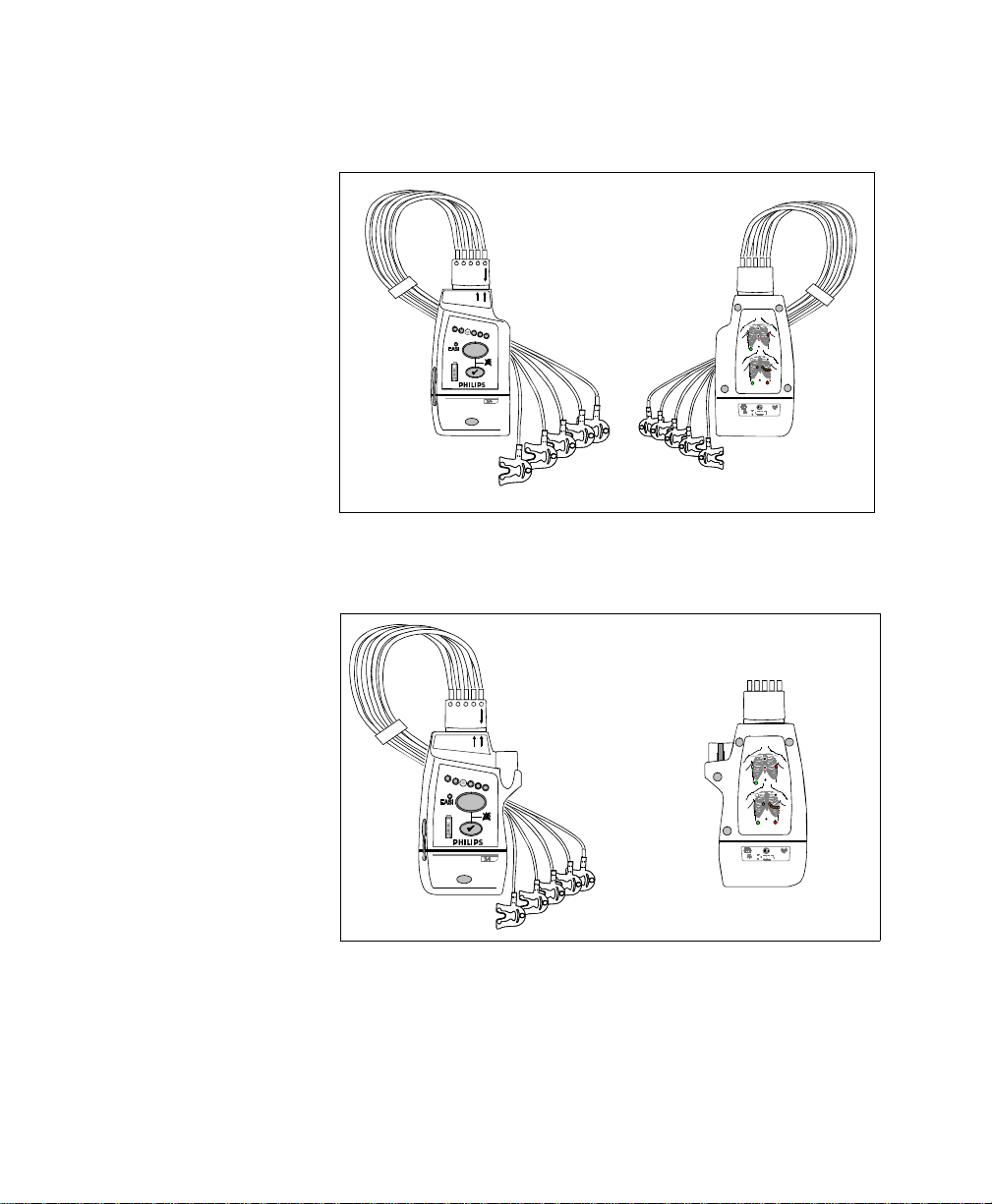
.
front
back
+
+
M2601B
IntelliVue TRx
IntelliVue TRx
M4841A
M4841A
EASI, 3
5
EASI, 3
5,6
IntelliVue TRx Transceiver - ECG Only
IntelliVue TRx
M4841A
+
EASI, 3
front
5,6
back
EASI
EASI
I
FCCID: XXXXXXXX
EASI
EASI
I
S
E
2
1
3
445566
S
E
1
FCCID: XXXXXXXX
A
A
2
3
445566
IntelliVue TRx
+
Transceiver - ECG/SpO
2
Introducing IntelliVue Telemetry
1-3

Draft - 1 Aug 08
IntelliVue Telemetry System
IntelliVue Telemetry System
The IntelliVue Telemetry System with Smart-Hopping Technology uses cellular
architecture to provide two-way communication between transceivers and the
IntelliVue Information Center. Smart-hopping technology dodges interference
and seeks out the strongest available signal to achieve seamless connections
wherever patients roam on the clinical network. The system connects a number
of individual devices to form a complete method of transporting patient data to a
central repository for subsequent distribution to clinical staff. Full patient
mobility is available within the areas defined by the wireless coverage of the
multiple Access Points.
Bidirectional
Capability
Telemetry transmits the patient’s measurements using radio waves. The signals
obtained from the patient travel from the transceiver to an access point in the
ceiling or wall and then to the Information Center. Bi-directional capability
enables you to remotely control certain transceiver functions from the
Information Center. Physiological data is transported from the transceiver, and a
reverse data channel enables data to be transported to the transceiver. Bidirectional operations include the following:
• Change SpO
• Enable or disable display of the pleth wave.
• Adjust the transceiver volume, or turn it off.
• Find Device feature for locating a lost transceiver within the coverage
area.
• Suppress SpO
• Return from Standby mode after a patient is away from the unit and not
being monitored by the IntelliVue Telemetry System.
• Configurable Alarm Pause/Suspend time initiated at the transceiver as
well as the Information Center.
• Transceiver location information displayed at the Information Center.
• Transceiver out of area notification at the Information Center.
measurement mode, or turn SpO2 measurement off.
2
technical alarms (INOPS) during NBP measurement.
2
1-4 Introducing IntelliVue Telemetry

Draft - 1 Aug 08
IntelliVue Telemetry System
Smarthopping
Technology
Bi-directional Signal Flow in the IntelliVue Telemetry System
Smart-hoppingTM technology provides dynamic management of the RF
spectrum used by each transceiver. This technology allows a virtually unlimited
number of transceivers to operate simultaneously within the IntelliVue
Telemetry System by creating a frequency-agile system that changes frequency
without user involvement or awareness whenever interference occurs.
Introducing IntelliVue Telemetry
1-5
Draft - 1 Aug 08
IntelliVue Telemetry System
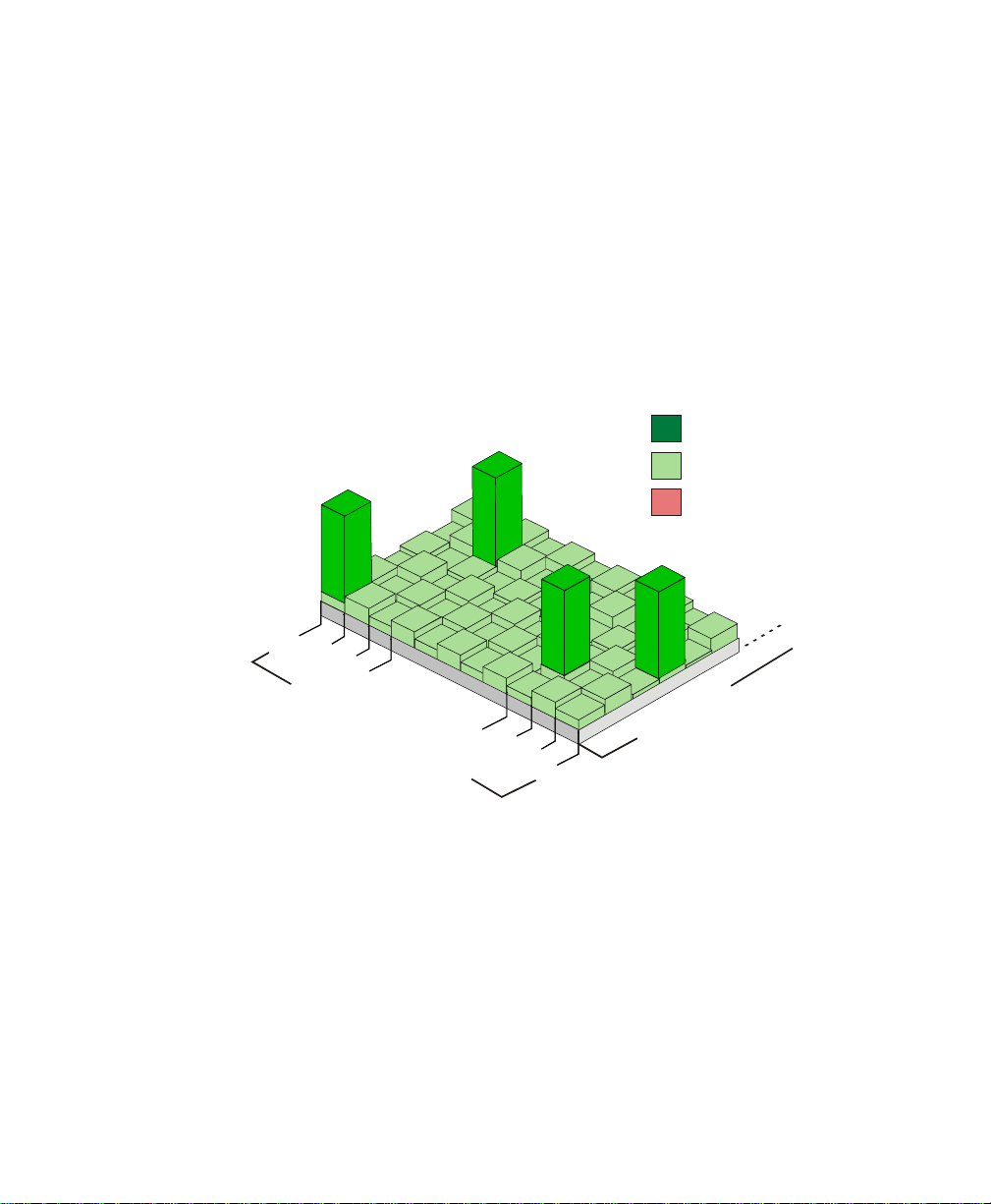
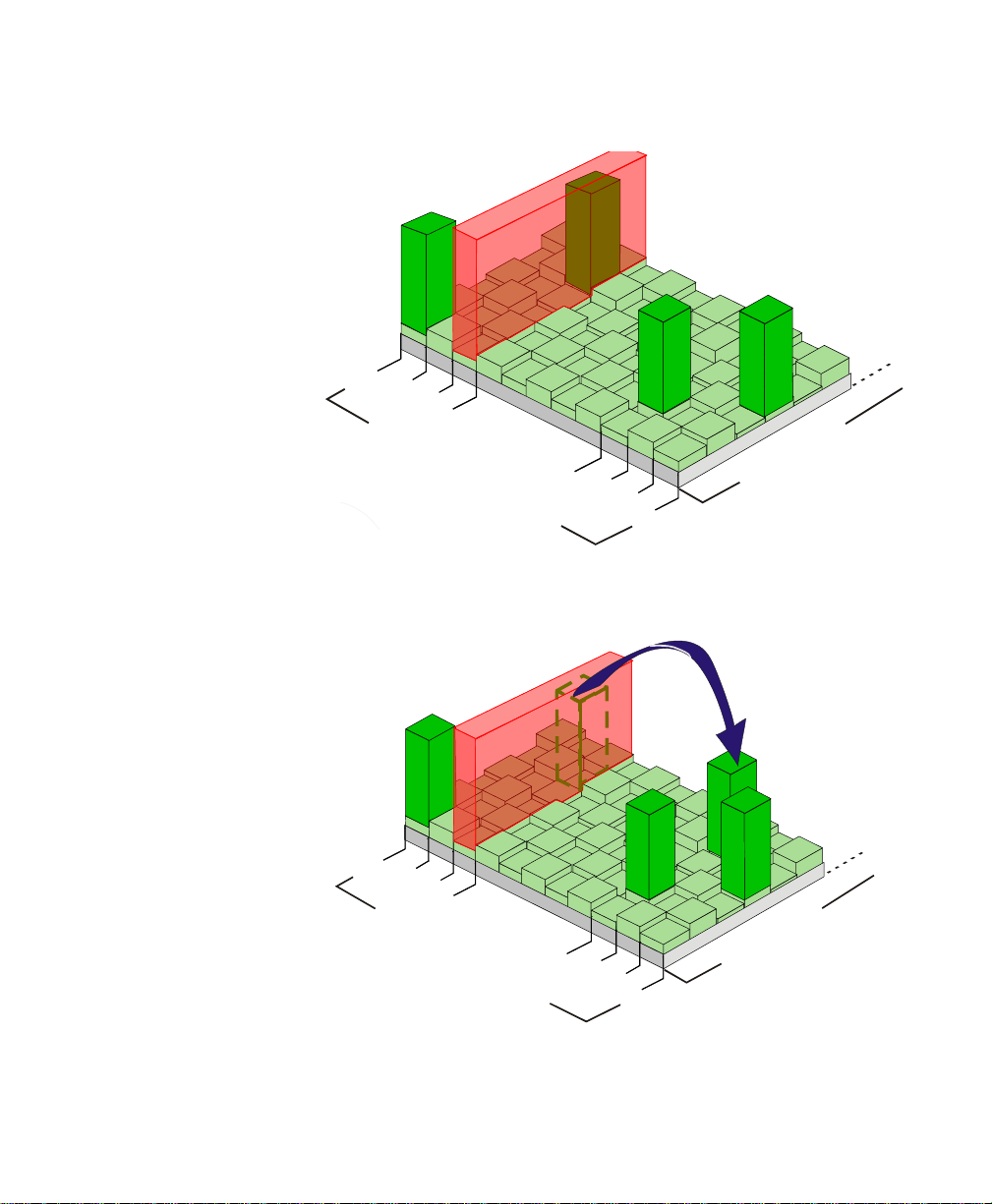
Smart-hopping enables the signal to avoid wireless interference. When baseline
noise is low (see illustrations following), telemetry signals reside in their
frequency/time slot locations. If excessive interference occurs, degrading the
signal, the telemetry signal then “hops” over the interference to a location that
provides optimal signal-to-noise performance.
In cases of excessive intermittent wireless interference, such as machinery
operation or construction activity, you should identify patterns of interference.
This information may assist your service provider in helping you resolve a
problem with interference.
Desired Signal
Baseline Noise
Interference
1395
1-6 Introducing IntelliVue Telemetry
1400
F
RE
Q
U
E
NC
1427
I
E
S
1432
M
I
T
S
T
O
SL
E
Normal Operation
Draft - 1 Aug 08
1395
IntelliVue Telemetry System
1395
1400
F
R
E
Q
U
E
N
C
1427
I
E
S
1432
M
I
T
S
T
O
L
S
E
Excessive Interference
1400
F
R
E
Q
U
E
N
C
1427
I
E
S
1432
M
I
T
S
T
LO
S
E
’Hop’ to New Frequency/Time Slot
Introducing IntelliVue Telemetry
1-7

Draft - 1 Aug 08
IntelliVue Clinical Network
Spectrum Sharing
The ITS4840A IntelliVue Telemetry System operates in the Wireless Medical
Telemetry Service bands (WMTS - USA only). WMTS uses radio frequency
spectrum which was allocated by the FCC for medical telemetry applications,
with a reduced potential for harmful interference. Although WMTS is managed
by a frequency coordination process, this coordination and licensing does not
grant the user an exclusive right to the spectrum on which their system operates,
and is subject to the terms and conditions of the FCC license. Other WMTS and
non-medical FCC licensees, as well as government agencies, may be legally
authorized to use this licensed spectrum.
The ITS4850A IntelliVue Telemetry System operates in the 2.4 GHz ISM band,
with up to six RF channels using a similar Smart-hopping technology as
described on page 1-5. The system also scans the selected six RF channels to
determine whether the spectrum is sufficiently clear. If the system is too
congested, a system level alert is provided.
IntelliVue Clinical Network
The IntelliVue Clinical Network (ICN) is the communication infrastructure
necessary to tie together all the patient monitoring systems within an
organization. This includes getting information to and from the IntelliVue
Information Center(s).
Patients can be monitored within the defined coverage areas. When a patient
goes out of range, an auditory out-of-range indicator sounds at the transceiver,
and a "No Signal" technical alarm at the Information Center notifies the clinical
staff.
The Network can include both wired and wireless devices. An installation
typically includes the following components:
1-8 Introducing IntelliVue Telemetry
• IntelliVue Clinical Network infrastructure.
• TRx4841A/TRx4851A Transceivers, bi-directional patient-worn devices.

Draft - 1 Aug 08
Transceiver Use with Other Equipment
• ITS4842A/ITS4852A Access Points (AP), placed within the areas with
defined coverage. APs are centers for bidirectional communication
between the transceivers and the Information Center.
• M3150B IntelliVue Information Center for centralized monitoring.
• ITS4843A/ITS4853A Core Access Points (optional) for expanded
coverage.
• M3154A IntelliVue Database Server (optional) for centralized data
management.
• M2636C TeleMon Companion Monitor (optional) for local alarms, NBP
measurement, and bedside display of patient data.
• M8105A MP5, M8102A MP2, and M3002A X2 IntelliVue Patient
Monitors (optional) for bedside display of patient data being sourced from
the transceiver.
Transceiver Use with Other Equipment
IntelliVue
Information
Center
TeleMon The transceiver can employ the full functionality of the M2636C TeleMon
The transceiver’s bi-directional capability enables remote control from the
Information Center for alarm, setup, and general monitoring functions. In
addition, the system supports Telemetry Overview, the pairing of a telemetry
bed with an IntelliVue Patient Monitor for bedside ECG viewing of a single
patient. Telemetry Overview provides the telemetry-monitored waveforms,
numerics, and alarms in an integrated form both on the bedside monitor and at
the IntelliVue Information Center. See “Chapter 10. Pairing Monitoring
Devices” for operating and configuration information.
Companion Monitor, including NBP measurement and local display of alarms.
Connection is made through an interface cable at the Monitor/Service port on
the transceiver. Please refer to “Transceiver Operation when Connected to
TeleMon” on page 9-19 for an operational summary, and the M2636C TeleMon
Instructions for Use for general operating instructions.
Introducing IntelliVue Telemetry
1-9

Draft - 1 Aug 08
Transceiver Use with Other Equipment
Patient
Bedside
Monitors
M2601B
Transmitters
Remote control of monitoring parameters such as NBP, SpO2, Alarm Suspend,
and Relearn, as well as limited overview of waves and data are supported
through Patient Bedside Monitors equipped with IntelliVue Instrument
Telemetry. Please refer to the Instructions for Use for the specific Patient
Monitor for operating information.
Patient Data can be sourced directly from the transceiver to MP5/MP5T, MP2 or
X2 Patient Monitors. The connection is made through a monitor interface cable
(MP5/MP5T only) or short range radio adapter (SRRA) inserted in the Monitor/
Service port and connected to the monitor. Non-networked MP5/MP5T
monitors can source patient data that includes SpO
temperature measurements to the Information Center. Please refer to the MP5
Instructions for Use for additional information.
+
If your hospital uses TRx and/or TRx
you can distinguish between them by:
• Name on the front of the device (TRx or M2601B)
• Label color (light gray for transceivers, dark gray for transmitters)
Transceivers and M2601B Transmitters,
, NBP and predictive
2
1-10 Introducing IntelliVue Telemetry

Draft - 1 Aug 08
2
Product Safety
This chapter consolidates the safety warnings that apply to use of the IntelliVue
Transceivers in a IntelliVue Clinical Network. These warnings are repeated
throughout the book in context where relevant. The chapter includes the
following sections:
• General Safety. . . . . . . . . . . . . . . . . . . . . . . . . . . . . . . . . . . . . . . . . . . . 2-2
• Battery. . . . . . . . . . . . . . . . . . . . . . . . . . . . . . . . . . . . . . . . . . . . . . . . . . 2-5
• ECG . . . . . . . . . . . . . . . . . . . . . . . . . . . . . . . . . . . . . . . . . . . . . . . . . . . 2-6
• ST/AR Arrhythmia . . . . . . . . . . . . . . . . . . . . . . . . . . . . . . . . . . . . . . . . 2-8
• ST/AR ST Segment . . . . . . . . . . . . . . . . . . . . . . . . . . . . . . . . . . . . . . 2-11
•SpO
• Cleaning . . . . . . . . . . . . . . . . . . . . . . . . . . . . . . . . . . . . . . . . . . . . . . . 2-16
• Accessories . . . . . . . . . . . . . . . . . . . . . . . . . . . . . . . . . . . . . . . . . . . . . 2-17
. . . . . . . . . . . . . . . . . . . . . . . . . . . . . . . . . . . . . . . . . . . . . . . . . . 2-12
2
Introduction
Product Safety 2-1

Draft - 1 Aug 08
General Safety
General Safety
The IntelliVue Telemetry System should not be used for primary
monitoring in applications where the momentary loss of the ECG is
unacceptable.
For continued safe use of this equipment, it is necessary that the listed
instructions are followed. Instructions in this manual in no way supersede
established medical procedures.
Do not touch the patient, or table, or instruments, during defibrillation.
The battery door must be closed during defibrillation. These steps protect
the clinician from high defibrillator voltage.
WarningWarning
WarningWarning
WarningWarning
WarningWarning
This device is not to be used in the vicinity of electrosurgical units because
such use may interrupt or interfere with the transmission of signals from
the transceiver.
WarningWarning
This equipment is not suitable for use in the presence of a flammable
anesthetic mixture with air, or with oxygen or nitrous oxide
2-2 Product Safety

Draft - 1 Aug 08
General Safety
WarningWarning
Do not use patient cables with detachable lead wires that have exposed male
pins. Electrocution could result if these pins are plugged into AC power.
WarningWarning
The system is not completely immune from radio interference although it is
designed to minimize interference through smart hopping. Sources of
interference that may be a problem include failing fluorescent lights and
construction equipment. See “Electromagnetic Compatibility” on page 12-5.
WarningWarning
The product should not be used next to or stacked with other equipment. If
you must stack the product, you must check that normal operation is
possible in the necessary configuration before the product is used on
patients.
WarningWarning
Do not use the transceiver for patient monitoring if it fails the Power On
Self Test.
WarningWarning
When the patient is showering, signal quality and leads off detection may be
compromised due to significant patient movement. Appropriate clinical
precautions must be taken.
Product Safety
2-3

Draft - 1 Aug 08
General Safety
WarningWarning
If the Alarms Suspend indicator on the transceiver remains illuminated
after the button combination to unsuspend alarms is pressed, a transceiver
malfunction may have occurred. (Alarms resume automatically after the
configured alarm suspend duration, or you can resume them manually at
the Information Center.) The transceiver should be replaced, and the
malfunctioning unit should be sent to your service provider.
WarningWarning
If the remote Silence key in the Overview window is enabled for IntelliVue
monitors connected to the Information Center, remote silencing for these
beds may be enabled in other clinical units
WarningWarning
Place the transceiver in a pouch or over clothing, or both, during patient
use. The transceiver should not touch the patient’s skin during use.
WarningWarning
To avoid the risk of strangulation, do not tie a pouch solely around the
patient’s neck.
WarningWarning
Patients should be instructed not to open the battery compartment while
the transceiver is in use.
WarningWarning
Failure on the part of the responsible individual hospital or institution
employing the use of this equipment to implement satisfactory maintenance
as needed may cause undue equipment failure and possible health hazards.
2-4 Product Safety

Draft - 1 Aug 08
Battery
Battery
WarningWarning
The battery door must be closed during defibrillation.
WarningWarning
Use Duracell Alkaline Batteries, size AA, MN 1500, 1.5V, to ensure
specified performance. Outdated, mismatched, or poor-quality batteries
can give unacceptable performance (e.g., insufficient Battery-Low warning
time). The use of fresh high-quality alkaline batteries is strongly
recommended.
WarningWarning
Certain failure conditions, such as short circuits, can cause a battery to
overheat during use. High temperatures can cause burns to the patient and/
or user. If the transceiver becomes hot to the touch, place it aside until it
cools. Then remove the batteries and discard them. Have the transceiver
operation checked by your service provider to identify the cause of
overheating.
WarningWarning
If you receive a BATTERY LOW alarm, the batteries must be promptly
replaced. A “Battery Low” condition that is not corrected will result in a
transceiver shutdown and cessation of monitoring.
Product Safety
2-5

Draft - 1 Aug 08
ECG
ECG
WarningWarning
Batteries should be removed from the transceiver at the end of the battery’s
useful life to prevent leakage.
If battery leakage should occur, use caution in removing the battery. The
leaked substance may cause eye or skin irritation. Avoid contact with skin.
Clean the battery compartment according to instructions in “Chapter 11.
Maintenance, Cleaning & Troubleshooting”. Wash hands.
WarningWarning
Always confirm Information Center observations with clinical observation
of the patient before administering interventions.
WarningWarning
Non-manufacturer supplied accessories and supplies can corrupt the
performance of the equipment. Use only AAMI-EC-12 compliant
electrodes with this device. Use of electrodes that are non-compliant may
provide erroneous results.
WarningWarning
Do not mix and match electrodes of different types. In particular, do not use
electrodes of dissimilar metals. This helps ensure optimal signal quality.
2-6 Product Safety

Draft - 1 Aug 08
ECG
WarningWarning
Every lead must be secured to an electrode on the patient.
Conductive parts of electrodes must not contact earth or other conductive
parts.
Philips recommends that you change the lead label only to reflect the
physical placement of electrodes. This will ensure a match between the
monitored lead and the label, and prevent any possible confusion.
WarningWarning
EASI derived 12-lead ECGs and their measurements are approximations to
conventional 12-lead ECGs. As the 12-lead ECG derived with EASI is not
exactly identical to the 12-lead conventional ECG obtained from an
electrocardiograph, it should not be used for diagnostic interpretations.
EASI lead placement is supported for adult patients only
WarningWarning
When switching between EASI and standard monitoring, there is a loss of
data for 30 seconds.
Product Safety
2-7

Draft - 1 Aug 08
ST/AR Arrhythmia
For Paced Patients
WarningWarning
The output power of the transceiver and other sources of radio frequency
energy, when used in the proximity of a pacemaker, can be sufficient to
interfere with pacemaker performance. Due to the shielding effects of the
body, internal pacemakers are somewhat less vulnerable than external
pacemakers. However, caution should be exercised when monitoring any
paced patient.
In order to minimize the possibility of interference, position electrodes,
electrode wires, and the transceiver as far away from the pacemaker as
possible.
Consult the pacemaker manufacturer for information on the RF
susceptibility of their products and the use of their products with the
IntelliVue Telemetry System. See the IntelliVue Information Center
Instructions for Use for additional information on monitoring paced
patients.
ST/AR Arrhythmia
WarningWarning
During complete heart block or pacemaker failure (to pace or capture), tall
P-waves (greater than 1/5 of the average R-wave height) can be erroneously
counted by the arrhythmia algorithm, resulting in missed detection of
cardiac arrest.
2-8 Product Safety
 Loading...