

Philips Medical Systems North America MDL4851 Users Manual

Page 1 of 7
Philips Medical Systems
Patient Monitoring
Quality & Regulatory Group
3000 Minuteman Road
Mailstop 0490
Andover, MA 01810
Tel: (978) 659-7383
Fax: (978) 685-5624
Application Note: MDL4851 Instrument Telemetry Module
Prepared by: Delroy Smith
Last revised: 29-Nov-06
The following information is intended for Philips internal use only. It is a guide for the incorporation of the MDL4851
module into Philips patient monitoring medical devices. Interested Philips engineers should contact the Wireless ER
Manager for additional information and referral to specific design specialists.
This document is an internally controlled document under the Philips Quality System.
Page 2 of 7
1 Table of Contents
1 Table of Contents 2
2 Introduction 2
3 Host Interface 3
4 Serial Connection 4
4.1 Serial Specification: 4
4.2 Maximum User Data Rate: 4
5 MDL4851-MODULE RF Shielding. 4
6 MDL4851-MODULE Mounting Considerations. 5
7 RF Input/Output, Antenna 5
7.1 RF Transmitter Specifications 5
8 Fault Conditions 6
8.1 Over/ Under Voltage 6
8.2 Excessive Signal Level on Serial Input 7
8.3 Excessive Data Rate on Serial Input 7
9 Accompanying Documentation for products incorporating the MDL4851-MODULE
7
2 Introduction
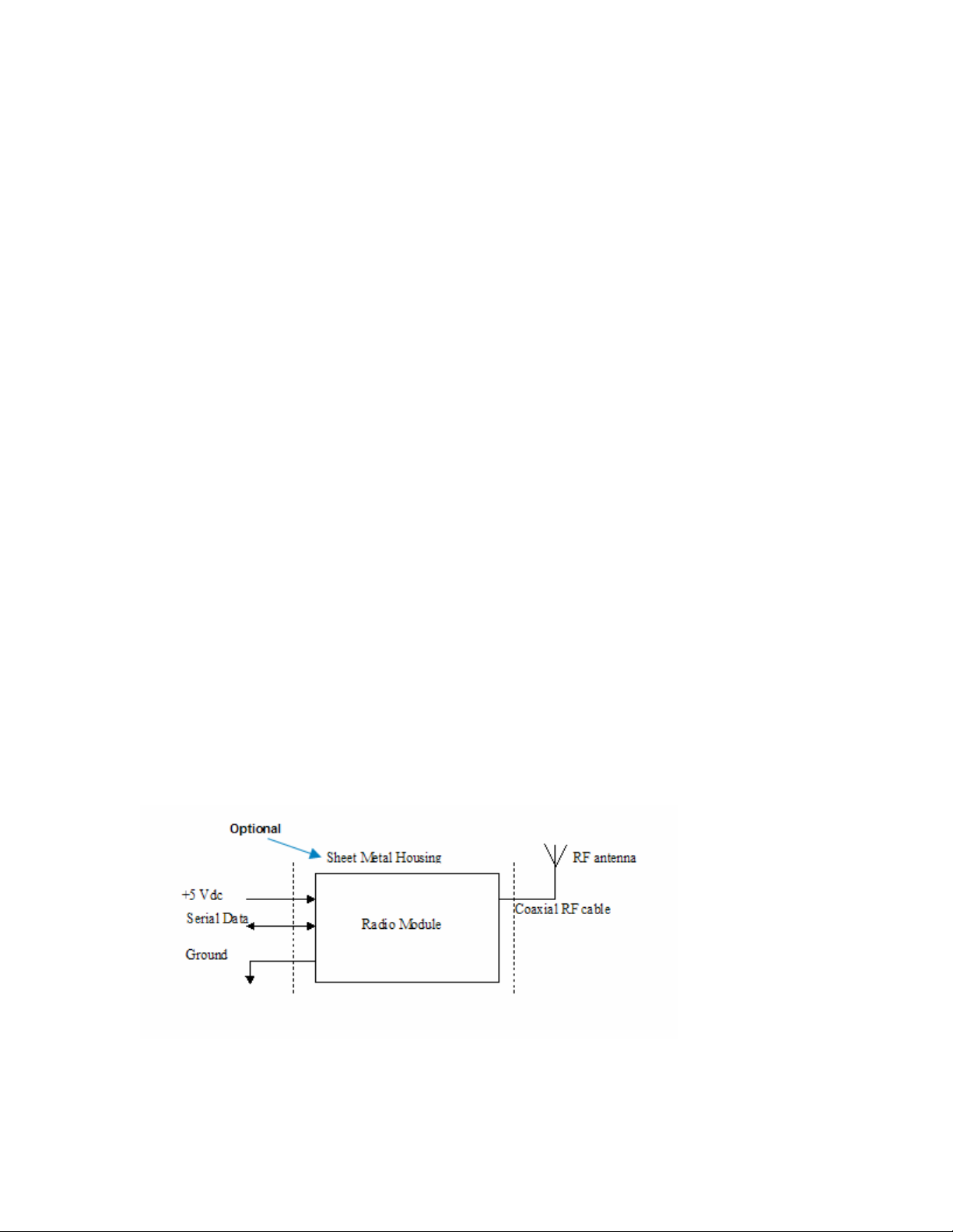
The MDL4851-MODULE is a serial network adapter designed to be used with specialized medical
devices manufactured by Philips Medical Systems (Figure 1). It enables the host medical device
to wirelessly establish bi directional communication with other remote devices using the Philips’
2.4GHz ROW infrastructure.
Figure 1: MDL4851-MODULE Block Diagram
Page 3 of 7
3 Host Interface
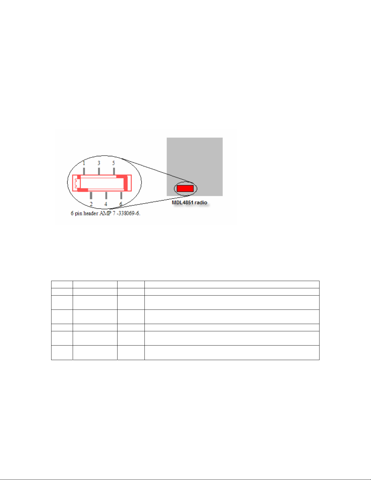
The MDL4851 radio module interfaces to the host though a single I/O connector (Figure 2). Via
this connector the host must supply DC power, signal ground and modulating data to the radio
module. The communication between the host device and the radio module is a two wire
asynchronous serial interface (Table 1).
Figure 2: MDL4851-MODULE Interface Host Connector
Pin Name I/O Function
1 Ground First of two ground connections for the module.
2 ITS_Tx OUT Serial data to host.
3 ITS_Rx IN Serial data from host.
4 Ground Second of two ground connections for the module.
5 +5 vdc + 5 vdc +/- 5%,
Sinks 38 mA average, 320 mA Peak during radio Tx/Rx
6 Not
Connected
Table 1: Host Connector pin assignment
 Loading...