

Philips Medical Systems North America M2601B Instructions for Use

Philips Telemetry System
with the M2601B Transmitter and
Telemetry Functions
at the IntelliVue Information Center
Notice
Operation of this equipment requires the prior coordination
with a frequency coordinator designated by the FCC for the
Wireless Medical Telemetry Service.
Instructions for Use
Part Number: M2600-92201
Printed in the U.S.A. November 2004
First Edition

Notice
Equipment specifications are subject to alteration without notice. All changes
will be in compliance with regulations governing manufacture of medical
equipment.
Printed in the USA.
Document number: M2600-92201
© Copyright 2004 Koninklijke Philips Electronics N.V. All Rights Reserved.
OxiCliq and OxiMax are registered trademarks of Nellcor Incorporated.
Printing History
New editions of this document incorporate all material updated since the
previous edition. Update packages may be issued between editions and contain
replacement and additional pages to be merged by a revision date at the bottom
of the page. Pages that are rearranged due to changes on a previous page are not
considered revised.
The documentation printing date and part number indicate its current edition.
The printing date changes when a new edition is printed. (Minor corrections and
updates which are incorporated at reprint do not cause the date to change.) The
document part number changes when extensive technical changes are
incorporated.
First Edition................................................................ November 2004
Philips Telemetry System, model M2600B is compatible with:
M2604A Philips Mainframe, #01D or #0EU, revision E.00.19
Philips Information Center, revisions F.00, E.01, E.00, D.01, D.00
M2636B TeleMon Companion Monitor, Options A02/A03
Philips Transmitter, model M2601A
Philips Transmitter, model M1400A/B/J
Note—Some features are not available on all products.
ii

About this Book
This book contains operating instructions for use of the M2601B Transmitter, a
part of the Philips Telemetry System. It also includes operational information for
the telemetry functions of the IntelliVue Information Center. The intended
audience is the clinician who uses and/or teaches others to use the equipment in
a healthcare environment. For operating information on other functionality of
the Information Center, see the IntelliVue Information Center Instructions for
Use (order number M3150-9001F). For preventive maintenance, repair, and test
methods for verification of device performance, refer to the M2600B Philips
Telemetry System Service Guide in the M2600B Documentation Kit, shipped
with the product (order number M2600-90323).
This book does not address Philips IntelliVue TRx transceivers or the Philips
IntelliVue Telemetry System. For information on those products, refer to the
manual Philips IntelliVue Telemetry System Instructions for Use (order number
M4841-91001).
Note—Standard and EASI M2601A Transmitters can be used with the Philips
Telemetry System and can operate simultaneously with M2601B Transmitters.
“What’s New” on page 1-2 summarizes the differences between the M2601B
and M2601A transmitters.
About this Book
iii

About this Book
Document
Conventions
Procedures
Procedures are indicated in text by the heading Task Summary followed by the
following table:
Step Action
1
2
3
Bold Typeface
Objects of actions in procedures appear in
bold typeface. Note the following
example:
Click the
Standby button.
Warnings
WarningWarning
Warnings are information you should know to avoid injuring patients and
personnel.
Cautions
Caution
Cautions are information you should know to avoid damaging your equipment
and software.
Notes
Note—Notes contain additional information on Philips Telemetry System usage.
iv

Product Safety Information
The warnings below refer to the following devices:
• Philips M2601B Transmitter
• Philips Telemetry System
• IntelliVue Information Center
WarningWarning
For continued safe use of this equipment, it is necessary that the listed
instructions are followed. Instructions in this manual in no way supersede
established medical procedures.
WarningWarning
Do not touch the patient, or table, or instruments during defibrillation. The
battery door must be closed during defibrillation. These steps protect the
clinician from high defibrillator voltage.
Product Safety Information
WarningWarning
This device is not to be used in the vicinity of electrosurgery units because
use may interrupt or interfere with the transmission of signals from the
transmitter.
WarningWarning
This equipment is not suitable for use in the presence of a flammable
anesthetic mixture with air or with oxygen or nitrous oxide.
v

Product Safety Information
WarningWarning
Do not use patient cables with detachable lead wires that have exposed male
pins. Electrocution could result if these pins are plugged into AC power.
WarningWarning
Use of product accessories (e.g., ECG lead sets, SpO2 sensors) other than
those prescribed by Philips could lead to patient injury.
WarningWarning
Strangulation Hazard! Under no circumstances should any pouch be tied
solely around a patient’s neck.
WarningWarning
ECG SAFETY FOR ALL PATIENTS
Always confirm Information Center observations with clinical observation
of the patient before administering interventions.
Every lead must be secured to an electrode on the patient.
Conductive parts of electrodes must not contact earth or other conductive
parts.
Philips recommends that you change the lead label only to reflect the
physical placement of electrodes. This will ensure a match between the
monitored lead and the label, and prevent any possible confusion.
When switching between EASI and Standard monitoring, there is a loss of
data for 30 seconds.
vi

Product Safety Information
WarningWarning
ECG SAFETY FOR PACED PATIENTS
The output power of the M2601B Transmitter and other sources of radio
frequency energy, when used in the proximity of a pacemaker, can be
sufficient to interfere with pacemaker performance. Due to the shielding
effects of the body, internal pacemakers are somewhat less vulnerable than
external pacemakers. However, caution should be exercised when
monitoring any paced patient.
In order to minimize the possibility of interference, position electrodes,
electrode wires, and the transmitter as far away from the pacemaker as
possible.
Consult the pacemaker manufacturer for information on the RF
susceptibility of their products and the use of their products with the
Philips Telemetry System. See the IntelliVue Information Center
Instructions for Use for additional information on monitoring paced
patients.
vii

Product Safety Information
WarningWarning
ST/AR ARRHYTHMIA SAFETY FOR ALL PATIENTS
During complete heart block or pacemaker failure (to pace or capture), tall
P-waves (greater than 1/5 of the average R-wave height) can be erroneously
counted by the arrhythmia algorithm, resulting in missed detection of
cardiac arrest.
Learning/Relearning
--If you initiate learning during ventricular rhythm, the ectopics can be
incorrectly learned as the normal QRS complex. This can result in missed
detection of subsequent events of V-Tach and V-Fib.
--When using EASI ECG monitoring, Relearn happens automatically when
there is a LEADS OFF technical alarm. If learning takes place during
ventricular rhythm, the ectopics can be incorrectly learned as the normal
QRS complex. This can result in missed detection of subsequent events of
V-Tach and V-Fib. Be sure to check the beat labels and initiate a relearn to
correct. Therefore, when a technical alarm is generated:
1. Respond to the technical alarm [for example, reconnect the electrode(s)].
2. Ensure that the arrhythmia algorithm is labeling beats correctly.
viii

Product Safety Information
WarningWarning
ST/AR ARRHYTHMIA SAFETY FOR PACED PATIENTS
It is possible that pacemaker pulses will not be detected when the ECG
analog output of a defibrillator or telemetry unit is plugged into a bedside
monitor. This can result in the arrhythmia algorithm’s failure to detect
pacemaker non-capture or asystole.
Some pace pulses can be difficult to reject. When this happens, the pulses
are counted as a QRS complex, and could result in an incorrect HR and
failure to detect cardiac arrest or some arrhythmias. Keep pacemaker
patients under close observation.
-- During complete heart block or pacemaker failure (to pace or capture),
tall P-waves (greater than 1/5 of the average R-wave height) can be
erroneously counted by the arrhythmia algorithm, resulting in missed
detection of cardiac arrest.
-- When arrhythmia monitoring paced patients who exhibit only intrinsic
rhythm, the monitor can erroneously count pace pulses as QRS complexes
when the algorithm first encounters them, resulting in missed detection of
cardiac arrest.
For patients who exhibit intrinsic rhythm only, the risk of missing cardiac
arrest can be reduced by monitoring these patients with the low heart rate
limit at or slightly above the basic/demand pacemaker rate. A low heart
rate alarm alerts you when the patient begins pacing. Proper detection and
classification of the paced rhythm can then be determined.
-- When an external pacemaker is being used on a patient, arrhythmia
monitoring is severely compromised due to the high energy level in the
pacer pulse. This can result in the arrhythmia algorithm’s failure to detect
pacemaker non-capture or asystole.
ix

Product Safety Information
x

Contents
1. Introduction to the Philips Telemetry System. . . . . . . . . . . . . . . . . . . . . . . . . 1-1
What’s New. . . . . . . . . . . . . . . . . . . . . . . . . . . . . . . . . . . . . . . . . . . . . . . . . . . . . . . . . . . . . . . . . . 1-2
New Transmitter . . . . . . . . . . . . . . . . . . . . . . . . . . . . . . . . . . . . . . . . . . . . . . . . . . . . . . . . . . 1-2
Connection to TeleMon . . . . . . . . . . . . . . . . . . . . . . . . . . . . . . . . . . . . . . . . . . . . . . . . . . . . . 1-4
Own Bed Overview . . . . . . . . . . . . . . . . . . . . . . . . . . . . . . . . . . . . . . . . . . . . . . . . . . . . . . . .1-4
Indications for Use . . . . . . . . . . . . . . . . . . . . . . . . . . . . . . . . . . . . . . . . . . . . . . . . . . . . . . . . . . . . 1-5
Regulatory Information . . . . . . . . . . . . . . . . . . . . . . . . . . . . . . . . . . . . . . . . . . . . . . . . . . . . .1-6
System Overview . . . . . . . . . . . . . . . . . . . . . . . . . . . . . . . . . . . . . . . . . . . . . . . . . . . . . . . . . . . . . 1-7
Transmitters. . . . . . . . . . . . . . . . . . . . . . . . . . . . . . . . . . . . . . . . . . . . . . . . . . . . . . . . . . . . . . . . . . 1-9
M2601B Transmitter Features . . . . . . . . . . . . . . . . . . . . . . . . . . . . . . . . . . . . . . . . . . . . . . . 1-10
Transmitter Controls - Front . . . . . . . . . . . . . . . . . . . . . . . . . . . . . . . . . . . . . . . . . . . . . . . . 1-11
Transmitter Controls - Back. . . . . . . . . . . . . . . . . . . . . . . . . . . . . . . . . . . . . . . . . . . . . . . . . 1-15
Sounds . . . . . . . . . . . . . . . . . . . . . . . . . . . . . . . . . . . . . . . . . . . . . . . . . . . . . . . . . . . . . . . . . 1-18
Transmitter Safety Information . . . . . . . . . . . . . . . . . . . . . . . . . . . . . . . . . . . . . . . . . . . . . . 1-18
Briefing the Patient . . . . . . . . . . . . . . . . . . . . . . . . . . . . . . . . . . . . . . . . . . . . . . . . . . . . . . . . . . . 1-19
Pouch Use . . . . . . . . . . . . . . . . . . . . . . . . . . . . . . . . . . . . . . . . . . . . . . . . . . . . . . . . . . . . . . 1-19
Securing the Pouch. . . . . . . . . . . . . . . . . . . . . . . . . . . . . . . . . . . . . . . . . . . . . . . . . . . . . . . .1-20
Showering . . . . . . . . . . . . . . . . . . . . . . . . . . . . . . . . . . . . . . . . . . . . . . . . . . . . . . . . . . . . . . 1-21
Making Monitoring Adjustments . . . . . . . . . . . . . . . . . . . . . . . . . . . . . . . . . . . . . . . . . . . . . . . . 1-22
Turning the Transmitter On/Off. . . . . . . . . . . . . . . . . . . . . . . . . . . . . . . . . . . . . . . . . . . . . . 1-22
Turning Telemetry Monitoring On/Off . . . . . . . . . . . . . . . . . . . . . . . . . . . . . . . . . . . . . . . . 1-23
Transmitter Auto Shutoff . . . . . . . . . . . . . . . . . . . . . . . . . . . . . . . . . . . . . . . . . . . . . . . . . . . 1-23
Turning Nurse Call On/Off . . . . . . . . . . . . . . . . . . . . . . . . . . . . . . . . . . . . . . . . . . . . . . . . . 1-23
Standby Mode . . . . . . . . . . . . . . . . . . . . . . . . . . . . . . . . . . . . . . . . . . . . . . . . . . . . . . . . . . . 1-24
Use with TeleMon B, Options A02/A03. . . . . . . . . . . . . . . . . . . . . . . . . . . . . . . . . . . . . . . . . . . 1-25
Operation with TeleMon . . . . . . . . . . . . . . . . . . . . . . . . . . . . . . . . . . . . . . . . . . . . . . . . . . . 1-25
Testing the Transmitter Functionality. . . . . . . . . . . . . . . . . . . . . . . . . . . . . . . . . . . . . . . . . . . . . 1-27
Self Test . . . . . . . . . . . . . . . . . . . . . . . . . . . . . . . . . . . . . . . . . . . . . . . . . . . . . . . . . . . . . . . . 1-27
Status Check. . . . . . . . . . . . . . . . . . . . . . . . . . . . . . . . . . . . . . . . . . . . . . . . . . . . . . . . . . . . . 1-28
Battery Information. . . . . . . . . . . . . . . . . . . . . . . . . . . . . . . . . . . . . . . . . . . . . . . . . . . . . . . . . . . 1-29
Battery Safety Information. . . . . . . . . . . . . . . . . . . . . . . . . . . . . . . . . . . . . . . . . . . . . . . . . . 1-29
Inserting/Removing Batteries . . . . . . . . . . . . . . . . . . . . . . . . . . . . . . . . . . . . . . . . . . . . . . . 1-31
Checking the Battery Power Level . . . . . . . . . . . . . . . . . . . . . . . . . . . . . . . . . . . . . . . . . . . 1-32
Receiver Module . . . . . . . . . . . . . . . . . . . . . . . . . . . . . . . . . . . . . . . . . . . . . . . . . . . . . . . . . . . . . 1-34
Receiver Mainframe . . . . . . . . . . . . . . . . . . . . . . . . . . . . . . . . . . . . . . . . . . . . . . . . . . . . . . . . . . 1-35
Antenna System. . . . . . . . . . . . . . . . . . . . . . . . . . . . . . . . . . . . . . . . . . . . . . . . . . . . . . . . . . . . . . 1-36
Contents-1

2. Alarms . . . . . . . . . . . . . . . . . . . . . . . . . . . . . . . . . . . . . . . . . . . . . . . . . . . . . . . . . 2-1
Alarm Indicators . . . . . . . . . . . . . . . . . . . . . . . . . . . . . . . . . . . . . . . . . . . . . . . . . . . . . . . . . . . . . . 2-2
Pause/Suspend Alarms . . . . . . . . . . . . . . . . . . . . . . . . . . . . . . . . . . . . . . . . . . . . . . . . . . . . . . . . . 2-2
Alarm Behavior with Own Bed Overview . . . . . . . . . . . . . . . . . . . . . . . . . . . . . . . . . . . . . . . . . . 2-3
Physiologic (Patient) Alarms . . . . . . . . . . . . . . . . . . . . . . . . . . . . . . . . . . . . . . . . . . . . . . . . . . . . 2-6
Technical Alarms (INOPs) . . . . . . . . . . . . . . . . . . . . . . . . . . . . . . . . . . . . . . . . . . . . . . . . . . . . . 2-11
3. ECG & ST/AR Measurement . . . . . . . . . . . . . . . . . . . . . . . . . . . . . . . . . . . . . . 3-1
Measuring ECG. . . . . . . . . . . . . . . . . . . . . . . . . . . . . . . . . . . . . . . . . . . . . . . . . . . . . . . . . . . . . . . 3-2
EASI ECG . . . . . . . . . . . . . . . . . . . . . . . . . . . . . . . . . . . . . . . . . . . . . . . . . . . . . . . . . . . . . . . 3-2
ECG Lead Sets . . . . . . . . . . . . . . . . . . . . . . . . . . . . . . . . . . . . . . . . . . . . . . . . . . . . . . . . . . . . 3-2
ECG Leads Monitored . . . . . . . . . . . . . . . . . . . . . . . . . . . . . . . . . . . . . . . . . . . . . . . . . . . . . . 3-4
Setting Up for ECG Monitoring . . . . . . . . . . . . . . . . . . . . . . . . . . . . . . . . . . . . . . . . . . . . . . . . . .3-7
Positioning ECG Electrodes. . . . . . . . . . . . . . . . . . . . . . . . . . . . . . . . . . . . . . . . . . . . . . . . . . 3-8
Connecting the ECG Cable . . . . . . . . . . . . . . . . . . . . . . . . . . . . . . . . . . . . . . . . . . . . . . . . . . . . .3-14
Verifying Electrode Connections . . . . . . . . . . . . . . . . . . . . . . . . . . . . . . . . . . . . . . . . . . . . . . . . 3-17
Making ECG Adjustments . . . . . . . . . . . . . . . . . . . . . . . . . . . . . . . . . . . . . . . . . . . . . . . . . . . . .3-18
Changing Lead/Label. . . . . . . . . . . . . . . . . . . . . . . . . . . . . . . . . . . . . . . . . . . . . . . . . . . . . . 3-18
Adjusting Wave Size . . . . . . . . . . . . . . . . . . . . . . . . . . . . . . . . . . . . . . . . . . . . . . . . . . . . . . 3-19
Monitoring During Leads Off . . . . . . . . . . . . . . . . . . . . . . . . . . . . . . . . . . . . . . . . . . . . . . . . . . .3-19
Lead Fallback. . . . . . . . . . . . . . . . . . . . . . . . . . . . . . . . . . . . . . . . . . . . . . . . . . . . . . . . . . . . 3-19
Extended Monitoring . . . . . . . . . . . . . . . . . . . . . . . . . . . . . . . . . . . . . . . . . . . . . . . . . . . . . . 3-20
Relearning . . . . . . . . . . . . . . . . . . . . . . . . . . . . . . . . . . . . . . . . . . . . . . . . . . . . . . . . . . . . . . 3-20
Using EASI Leads to Troubleshoot . . . . . . . . . . . . . . . . . . . . . . . . . . . . . . . . . . . . . . . . . . . 3-21
Optimizing System Performance . . . . . . . . . . . . . . . . . . . . . . . . . . . . . . . . . . . . . . . . . . . . . . . . 3-22
The Telemetry Signal. . . . . . . . . . . . . . . . . . . . . . . . . . . . . . . . . . . . . . . . . . . . . . . . . . . . . . 3-22
Troubleshooting Signal Disturbance . . . . . . . . . . . . . . . . . . . . . . . . . . . . . . . . . . . . . . . . . . 3-23
Dropouts. . . . . . . . . . . . . . . . . . . . . . . . . . . . . . . . . . . . . . . . . . . . . . . . . . . . . . . . . . . . . . . . 3-23
Muscle and Movement Artifact . . . . . . . . . . . . . . . . . . . . . . . . . . . . . . . . . . . . . . . . . . . . . . 3-24
ECG Safety Information . . . . . . . . . . . . . . . . . . . . . . . . . . . . . . . . . . . . . . . . . . . . . . . . . . . . . . . 3-27
ST/AR Arrhythmia Analysis. . . . . . . . . . . . . . . . . . . . . . . . . . . . . . . . . . . . . . . . . . . . . . . . . . . .3-28
ECG and ST/AR Alarms . . . . . . . . . . . . . . . . . . . . . . . . . . . . . . . . . . . . . . . . . . . . . . . . . . . 3-30
ST/AR Arrhythmia Safety Information . . . . . . . . . . . . . . . . . . . . . . . . . . . . . . . . . . . . . . . . 3-31
4. ST/AR ST Segment Monitoring. . . . . . . . . . . . . . . . . . . . . . . . . . . . . . . . . . . . . 4-1
ST/AR ST Algorithm . . . . . . . . . . . . . . . . . . . . . . . . . . . . . . . . . . . . . . . . . . . . . . . . . . . . . . . . . . 4-2
Intended Use . . . . . . . . . . . . . . . . . . . . . . . . . . . . . . . . . . . . . . . . . . . . . . . . . . . . . . . . . . . . . 4-2
Patient Population . . . . . . . . . . . . . . . . . . . . . . . . . . . . . . . . . . . . . . . . . . . . . . . . . . . . . . . . . 4-2
The Measurement. . . . . . . . . . . . . . . . . . . . . . . . . . . . . . . . . . . . . . . . . . . . . . . . . . . . . . . . . . 4-3
How the Algorithm Works. . . . . . . . . . . . . . . . . . . . . . . . . . . . . . . . . . . . . . . . . . . . . . . . . . . 4-4
Contents-2

Displayed ST Data . . . . . . . . . . . . . . . . . . . . . . . . . . . . . . . . . . . . . . . . . . . . . . . . . . . . . . . . .4-4
EASI ST Analysis. . . . . . . . . . . . . . . . . . . . . . . . . . . . . . . . . . . . . . . . . . . . . . . . . . . . . . . . . .4-4
Adjusting Measurement Points . . . . . . . . . . . . . . . . . . . . . . . . . . . . . . . . . . . . . . . . . . . . . . . . . . .4-5
Establishing ST Reference Beats (Baseline) . . . . . . . . . . . . . . . . . . . . . . . . . . . . . . . . . . . . . . . . .4-7
Turning ST On/Off. . . . . . . . . . . . . . . . . . . . . . . . . . . . . . . . . . . . . . . . . . . . . . . . . . . . . . . . . . . . .4-7
ST Alarms . . . . . . . . . . . . . . . . . . . . . . . . . . . . . . . . . . . . . . . . . . . . . . . . . . . . . . . . . . . . . . . . . . .4-8
ST Alarm Adjustments . . . . . . . . . . . . . . . . . . . . . . . . . . . . . . . . . . . . . . . . . . . . . . . . . . . . . .4-9
5. SpO2 Monitoring. . . . . . . . . . . . . . . . . . . . . . . . . . . . . . . . . . . . . . . . . . . . . . . . . 5-1
About the Pulse Oximetry Measurement . . . . . . . . . . . . . . . . . . . . . . . . . . . . . . . . . . . . . . . . . . . .5-2
Pulse Indication. . . . . . . . . . . . . . . . . . . . . . . . . . . . . . . . . . . . . . . . . . . . . . . . . . . . . . . . . . . .5-3
SpO2 Information for the User . . . . . . . . . . . . . . . . . . . . . . . . . . . . . . . . . . . . . . . . . . . . . . . .5-4
Preparing for Telemetry SpO
SpO
Sensors . . . . . . . . . . . . . . . . . . . . . . . . . . . . . . . . . . . . . . . . . . . . . . . . . . . . . . . . . . . . . . . . .5-8
2
Disposable Sensors . . . . . . . . . . . . . . . . . . . . . . . . . . . . . . . . . . . . . . . . . . . . . . . . . . . . . . . . .5-8
Reusable Sensors . . . . . . . . . . . . . . . . . . . . . . . . . . . . . . . . . . . . . . . . . . . . . . . . . . . . . . . . . .5-8
Selecting an SpO2 Sensor . . . . . . . . . . . . . . . . . . . . . . . . . . . . . . . . . . . . . . . . . . . . . . . . . . . . . . .5-9
Applying the Sensor. . . . . . . . . . . . . . . . . . . . . . . . . . . . . . . . . . . . . . . . . . . . . . . . . . . . . . . . . . .5-12
Sensor Application Safety Information . . . . . . . . . . . . . . . . . . . . . . . . . . . . . . . . . . . . . . . .5-12
Adult Finger Sensor (M1191A) . . . . . . . . . . . . . . . . . . . . . . . . . . . . . . . . . . . . . . . . . . . . . .5-14
Small Adult/Pediatric Finger Sensor (M1192A) . . . . . . . . . . . . . . . . . . . . . . . . . . . . . . . . .5-15
Ear Clip Sensor (M1194A) . . . . . . . . . . . . . . . . . . . . . . . . . . . . . . . . . . . . . . . . . . . . . . . . . .5-16
Connecting the SpO2 Cable. . . . . . . . . . . . . . . . . . . . . . . . . . . . . . . . . . . . . . . . . . . . . . . . . . . . .5-17
Making SpO
SpO
Measurements . . . . . . . . . . . . . . . . . . . . . . . . . . . . . . . . . . . . . . . . . . . . . . . . . . . .5-18
2
Measurement when Connected to TeleMon . . . . . . . . . . . . . . . . . . . . . . . . . . . . . . . .5-18
2
Making a Spot Check Measurement. . . . . . . . . . . . . . . . . . . . . . . . . . . . . . . . . . . . . . . . . . .5-19
Monitoring SpO2 Continuously . . . . . . . . . . . . . . . . . . . . . . . . . . . . . . . . . . . . . . . . . . . . . .5-20
Turning SpO2 Monitoring Off . . . . . . . . . . . . . . . . . . . . . . . . . . . . . . . . . . . . . . . . . . . . . . .5-20
Turning the SpO2 Parameter On/Off . . . . . . . . . . . . . . . . . . . . . . . . . . . . . . . . . . . . . . . . . .5-21
SpO
Parameter Auto ON. . . . . . . . . . . . . . . . . . . . . . . . . . . . . . . . . . . . . . . . . . . . . . . . . . .5-22
2
Turning SpO
Alarms On/Off. . . . . . . . . . . . . . . . . . . . . . . . . . . . . . . . . . . . . . . . . . . . . . . .5-22
2
Turning the Pulse Parameter On/Off . . . . . . . . . . . . . . . . . . . . . . . . . . . . . . . . . . . . . . . . . .5-23
Measurement Limitations . . . . . . . . . . . . . . . . . . . . . . . . . . . . . . . . . . . . . . . . . . . . . . . . . . . . . .5-24
Optimizing Sensor Performance . . . . . . . . . . . . . . . . . . . . . . . . . . . . . . . . . . . . . . . . . . . . . . . . .5-25
SpO
Alarms and Technical Alarms . . . . . . . . . . . . . . . . . . . . . . . . . . . . . . . . . . . . . . . . . . . . . .5-25
2
Monitoring . . . . . . . . . . . . . . . . . . . . . . . . . . . . . . . . . . . . . . . . . .5-7
2
Contents-3

6. Maintenance and Configuration . . . . . . . . . . . . . . . . . . . . . . . . . . . . . . . . . . . . 6-1
Troubleshooting . . . . . . . . . . . . . . . . . . . . . . . . . . . . . . . . . . . . . . . . . . . . . . . . . . . . . . . . . . . . . . 6-2
Basic Troubleshooting . . . . . . . . . . . . . . . . . . . . . . . . . . . . . . . . . . . . . . . . . . . . . . . . . . . . . .6-2
Testing Alarms. . . . . . . . . . . . . . . . . . . . . . . . . . . . . . . . . . . . . . . . . . . . . . . . . . . . . . . . . . . . 6-2
Maintenance . . . . . . . . . . . . . . . . . . . . . . . . . . . . . . . . . . . . . . . . . . . . . . . . . . . . . . . . . . . . . . . . . 6-3
Transmitter Cleaning, Disinfection, & Cross-Infection Prevention . . . . . . . . . . . . . . . . . . . . . . . 6-4
Cleaning the Transmitter . . . . . . . . . . . . . . . . . . . . . . . . . . . . . . . . . . . . . . . . . . . . . . . . . . . .6-4
Disinfecting the Transmitter . . . . . . . . . . . . . . . . . . . . . . . . . . . . . . . . . . . . . . . . . . . . . . . . . 6-5
Cross-Infection Prevention for the Transmitter . . . . . . . . . . . . . . . . . . . . . . . . . . . . . . . . . . . 6-7
Receiver Mainframe Cleaning . . . . . . . . . . . . . . . . . . . . . . . . . . . . . . . . . . . . . . . . . . . . . . . . . . 6-15
Configuration . . . . . . . . . . . . . . . . . . . . . . . . . . . . . . . . . . . . . . . . . . . . . . . . . . . . . . . . . . . . . . . 6-16
Configuration Settings. . . . . . . . . . . . . . . . . . . . . . . . . . . . . . . . . . . . . . . . . . . . . . . . . . . . . . . . . 6-17
M2604A Mainframe . . . . . . . . . . . . . . . . . . . . . . . . . . . . . . . . . . . . . . . . . . . . . . . . . . . . . . 6-17
Philips M2601B Transmitter . . . . . . . . . . . . . . . . . . . . . . . . . . . . . . . . . . . . . . . . . . . . . . . . 6-19
Changing the Configuration. . . . . . . . . . . . . . . . . . . . . . . . . . . . . . . . . . . . . . . . . . . . . . . . . 6-19
7. System Safety and Specifications. . . . . . . . . . . . . . . . . . . . . . . . . . . . . . . . . . . . 7-1
Product Safety . . . . . . . . . . . . . . . . . . . . . . . . . . . . . . . . . . . . . . . . . . . . . . . . . . . . . . . . . . . . . . . . 7-2
. . . . . . . . . . . . . . . . . . . . . . . . . . . . . . . . . . . . . . . . . . . . . . . . . . . . . . . . . . . . . . . . . . . . . . . . 7-2
System Classification. . . . . . . . . . . . . . . . . . . . . . . . . . . . . . . . . . . . . . . . . . . . . . . . . . . . . . . 7-3
Essential Performance . . . . . . . . . . . . . . . . . . . . . . . . . . . . . . . . . . . . . . . . . . . . . . . . . . . . . .7-4
Philips Telemetry System Warnings. . . . . . . . . . . . . . . . . . . . . . . . . . . . . . . . . . . . . . . . . . . . . . . 7-4
Electromagnetic Compatibility . . . . . . . . . . . . . . . . . . . . . . . . . . . . . . . . . . . . . . . . . . . . . . . . . . . 7-5
M2600B Philips Telemetry System Testing . . . . . . . . . . . . . . . . . . . . . . . . . . . . . . . . . . . . . 7-5
FCC Compliance (USA only) . . . . . . . . . . . . . . . . . . . . . . . . . . . . . . . . . . . . . . . . . . . . . . . . 7-7
Canadian Radio Equipment Compliance (Canada Only) . . . . . . . . . . . . . . . . . . . . . . . . . . . 7-7
System Symbols . . . . . . . . . . . . . . . . . . . . . . . . . . . . . . . . . . . . . . . . . . . . . . . . . . . . . . . . . . . . . . 7-9
Type CF Defibrillation Proof. . . . . . . . . . . . . . . . . . . . . . . . . . . . . . . . . . . . . . . . . . . . . . . . 7-14
Installation and Maintenance Safety . . . . . . . . . . . . . . . . . . . . . . . . . . . . . . . . . . . . . . . . . . . . . . 7-14
Installation . . . . . . . . . . . . . . . . . . . . . . . . . . . . . . . . . . . . . . . . . . . . . . . . . . . . . . . . . . . . . . 7-14
Preventive Maintenance. . . . . . . . . . . . . . . . . . . . . . . . . . . . . . . . . . . . . . . . . . . . . . . . . . . . 7-18
End of Life . . . . . . . . . . . . . . . . . . . . . . . . . . . . . . . . . . . . . . . . . . . . . . . . . . . . . . . . . . . . . . 7-18
Additional Safety Information . . . . . . . . . . . . . . . . . . . . . . . . . . . . . . . . . . . . . . . . . . . . . . . . . .7-19
System Specifications . . . . . . . . . . . . . . . . . . . . . . . . . . . . . . . . . . . . . . . . . . . . . . . . . . . . . . . . . 7-20
Battery Life Specifications. . . . . . . . . . . . . . . . . . . . . . . . . . . . . . . . . . . . . . . . . . . . . . . . . . 7-20
Environmental Specifications . . . . . . . . . . . . . . . . . . . . . . . . . . . . . . . . . . . . . . . . . . . . . . . 7-21
Electrical Power Specifications . . . . . . . . . . . . . . . . . . . . . . . . . . . . . . . . . . . . . . . . . . . . . . 7-22
Antenna System Specifications . . . . . . . . . . . . . . . . . . . . . . . . . . . . . . . . . . . . . . . . . . . . . . 7-26
Measurement Specifications . . . . . . . . . . . . . . . . . . . . . . . . . . . . . . . . . . . . . . . . . . . . . . . . 7-30
Contents-4

A. Optional Patient Monitor/Holter Interface (Analog Output) . . . . . . . . . . . A-1
Overview . . . . . . . . . . . . . . . . . . . . . . . . . . . . . . . . . . . . . . . . . . . . . . . . . . . . . . . . . . . . . . . . . . . A-2
Correct Labeling . . . . . . . . . . . . . . . . . . . . . . . . . . . . . . . . . . . . . . . . . . . . . . . . . . . . . . . . . . A-2
Analog Output Bedside Monitor Cables . . . . . . . . . . . . . . . . . . . . . . . . . . . . . . . . . . . . . . . . . . . A-3
Lead Placement and Selection . . . . . . . . . . . . . . . . . . . . . . . . . . . . . . . . . . . . . . . . . . . . . . . . . . . A-5
Using Non-Standard Lead Placement. . . . . . . . . . . . . . . . . . . . . . . . . . . . . . . . . . . . . . . . . . A-5
Controls for Telemetry Setup. . . . . . . . . . . . . . . . . . . . . . . . . . . . . . . . . . . . . . . . . . . . . . . . . . . . A-6
Functionality with Paced Waves . . . . . . . . . . . . . . . . . . . . . . . . . . . . . . . . . . . . . . . . . . . . . . . . . A-6
Technical Alarms (Inoperative Conditions). . . . . . . . . . . . . . . . . . . . . . . . . . . . . . . . . . . . . . . . . A-7
Holter Interface . . . . . . . . . . . . . . . . . . . . . . . . . . . . . . . . . . . . . . . . . . . . . . . . . . . . . . . . . . . . . . A-8
B. Accessory List . . . . . . . . . . . . . . . . . . . . . . . . . . . . . . . . . . . . . . . . . . . . . . . . . . B-1
Accessory Safety . . . . . . . . . . . . . . . . . . . . . . . . . . . . . . . . . . . . . . . . . . . . . . . . . . . . . . . . . . . . . B-1
ECG Accessories . . . . . . . . . . . . . . . . . . . . . . . . . . . . . . . . . . . . . . . . . . . . . . . . . . . . . . . . . . . . . B-2
SpO2 Accessories . . . . . . . . . . . . . . . . . . . . . . . . . . . . . . . . . . . . . . . . . . . . . . . . . . . . . . . . . . . . B-4
C. Sales and Support Offices . . . . . . . . . . . . . . . . . . . . . . . . . . . . . . . . . . . . . . . . C-1
Contents-5

Contents-6

1
Introduction to the
Philips Telemetry System
This chapter introduces the Philips Telemetry System. It includes the following
sections:
• What’s New. . . . . . . . . . . . . . . . . . . . . . . . . . . . . . . . . . . . . . . . . . . . . .1-2
• Indications for Use . . . . . . . . . . . . . . . . . . . . . . . . . . . . . . . . . . . . . . . . 1-5
• System Overview . . . . . . . . . . . . . . . . . . . . . . . . . . . . . . . . . . . . . . . . . 1-7
• Transmitters. . . . . . . . . . . . . . . . . . . . . . . . . . . . . . . . . . . . . . . . . . . . . . 1-9
• Briefing the Patient . . . . . . . . . . . . . . . . . . . . . . . . . . . . . . . . . . . . . . . 1-19
• Making Monitoring Adjustments . . . . . . . . . . . . . . . . . . . . . . . . . . . . 1-22
• Use with TeleMon B, Options A02/A03. . . . . . . . . . . . . . . . . . . . . . . 1-25
• Testing the Transmitter Functionality . . . . . . . . . . . . . . . . . . . . . . . . . 1-27
• Battery Information. . . . . . . . . . . . . . . . . . . . . . . . . . . . . . . . . . . . . . .1-29
• Receiver Module . . . . . . . . . . . . . . . . . . . . . . . . . . . . . . . . . . . . . . . . .1-34
• Receiver Mainframe . . . . . . . . . . . . . . . . . . . . . . . . . . . . . . . . . . . . . . 1-35
• Antenna System . . . . . . . . . . . . . . . . . . . . . . . . . . . . . . . . . . . . . . . . .1-36
Introduction
Introduction to the Philips Telemetry System 1-1

What’s New
What’s New
This section highlights the differences between the M2600B Philips Telemetry
System, utilizing the M2601B Transmitter and the Philips M2600A Telemetry
System, Release C, utilizing the M2601A Transmitter.
New Transmitter
Differences
Between
Transm itters
Function One transmitter for both Standard and
The main difference between the two systems is the introduction of the new
M2601B transmitter.
The following table summarizes the differences between the two transmitters.
M2601B M2601A
EASI monitoring -- clinician simply
changes the ECG lead set position
FAST (Fourier Artifact Suppression
Technology) SpO
Continuous and Spot Check (Manual)
SpO
measurements
2
algorithm
2
Separate Standard or EASI versions of
transmitter
Traditional (not motion tolerant) SpO
algorithm
Continuous, Spot Check (Manual), and
Intermittent (1- and 5-minute) SpO2
measurements
2
1-2 Introduction to the Philips Telemetry System

M2601B M2601A
What’s New
Controls &
Indicators
Spot Check SpO
sensor cable
initiated by inserting
2
Auditory feedback for Spot Check and
self test
Two electrode placement diagrams
show both Standard and EASI
placement
Check button for verifying transmitter
status: lead set type, battery level,
EASI indicator (if in use)
Battery gauge to indicate power level N/A
Audible volume/mute configurations N/A
Audible pulse detection during Spot
Check measurement
Unit designator label on battery
compartment
Physical Smaller and lighter ECG-only
transmitter
ECG/SpO
transmitter approximately
2
same size as the M2601A
Manual measurement initiated by
button push on transmitter
N/A
One electrode placement diagram
appropriate for the transmitter: either
Standard or EASI placement
N/A
N/A
N/A
One-size transmitter (ECG-only or
ECG/SpO
)
2
Power Source Battery Type: 2 AA Alkaline Battery Types: 1 9-volt Alkaline,
Lithium, Zinc Air
No Support for Battery Extender Compatible with Battery Extender
Accessories New 5-wire lead sets, with color-
coded lead wires available
Introduction to the Philips Telemetry System
1-3

What’s New
Connection to TeleMon
Own Bed Overview
The M2601B Transmitter also has a different method of connecting to the
TeleMon Companion Monitor:
• M2601B: Transmitter is connected to the outside of TeleMon via a 3meter tether cable.
• M2601A: Transmitter is docked in TeleMon.
The system supports the concept of Own Bed Overview, the pairing of a
telemetry bed and an IntelliVue Patient Monitor (Release B.1 or higher) for a
single patient. Own Bed Overview provides the telemetry-monitor data
(waveforms, parameters, and alarms) in an integrated form both on the bedside
monitor and at the IntelliVue Information Center.
Own Bed Overview is available with both the M2601B and M2601A
transmitters.
Information on Own Bed Overview can be found in the IntelliVue Patient
Monitor Instructions for Use and the IntelliVue Information Center Instructions
for Use. In this book, “Alarm Behavior with Own Bed Overview” on page 2-3
summarizes alarm functionality with Own Bed Overview.
1-4 Introduction to the Philips Telemetry System

Indications for Use
Indications for Use
The paragraphs below are the elements of the indications for use statement for
the Philips Telemetry System.
Condition The licensed clinician decides that the Philips Telemetry System should be used
to monitor the patient.
Prescription
Versus Over-
the-Counter
Part of the
Body or Type
of Tissue with
which the
Device
Interacts
Frequency of
Use
Physiological
Purpose
Patient
Population
The Philips Telemetry System is a prescription device.
The ECG signal is obtained from accessory electrodes in contact with the
patient’s skin. The SpO
signal is obtained from an accessory sensor in contact
2
with the patient’s skin.
As prescribed by a licensed physician.
To monitor the ECG and SpO
of patients on the order of a licensed physician.
2
Adult and pediatric patients.
Introduction to the Philips Telemetry System
1-5

Indications for Use
Intended Use The Philips Telemetry System is a comprehensive ambulatory system solution
for the intermediate care unit for adult and pediatric patients. The foundation of
the system is a transmitter that can capture and transmit ECG signals and SpO
values (if available) that are then processed and displayed on the IntelliVue
Information Center. The Information Center generates alarms and recordings,
thus notifying clinicians of changes in patients' conditions. The Telemetry
System communicates with other devices via the Philips patient care system.
WarningWarning
United States law restricts this device to sale by or on the order of a
physician. This product is intended for use in health care facilities by
trained health care professionals. It is not intended for home use.
2
Regulatory Information
This device is not for use with infant or neonatal patients.
The transmitter and related accessories are in compliance with the relevant
requirements of EN ISO 10993-1 for Biocompatibility. The transmitter is not
designed for direct contact with the patient’s skin. The accompanying pouch is
the appropriate means for holding the transmitter.
Use of the transmitter is restricted to one patient at a time.
The system is not intended to be connected to public mains as defined in
CISPR 11.
1-6 Introduction to the Philips Telemetry System

System Overview
The Philips Telemetry System is used with the IntelliVue Information Center to
provide multi-parameter measurements for transitional care and other
ambulatory monitoring environments for adult and pediatric patients. The
system:
• Enunciates patient monitoring alarms.
• Monitors adult and pediatric patients’ ECG.
• Provides ST/AR arrhythmia detection.
• Measures pulsatile arterial oxygen saturation (SpO
• Enables viewing of ECG and SpO
• Makes ST segment measurements.
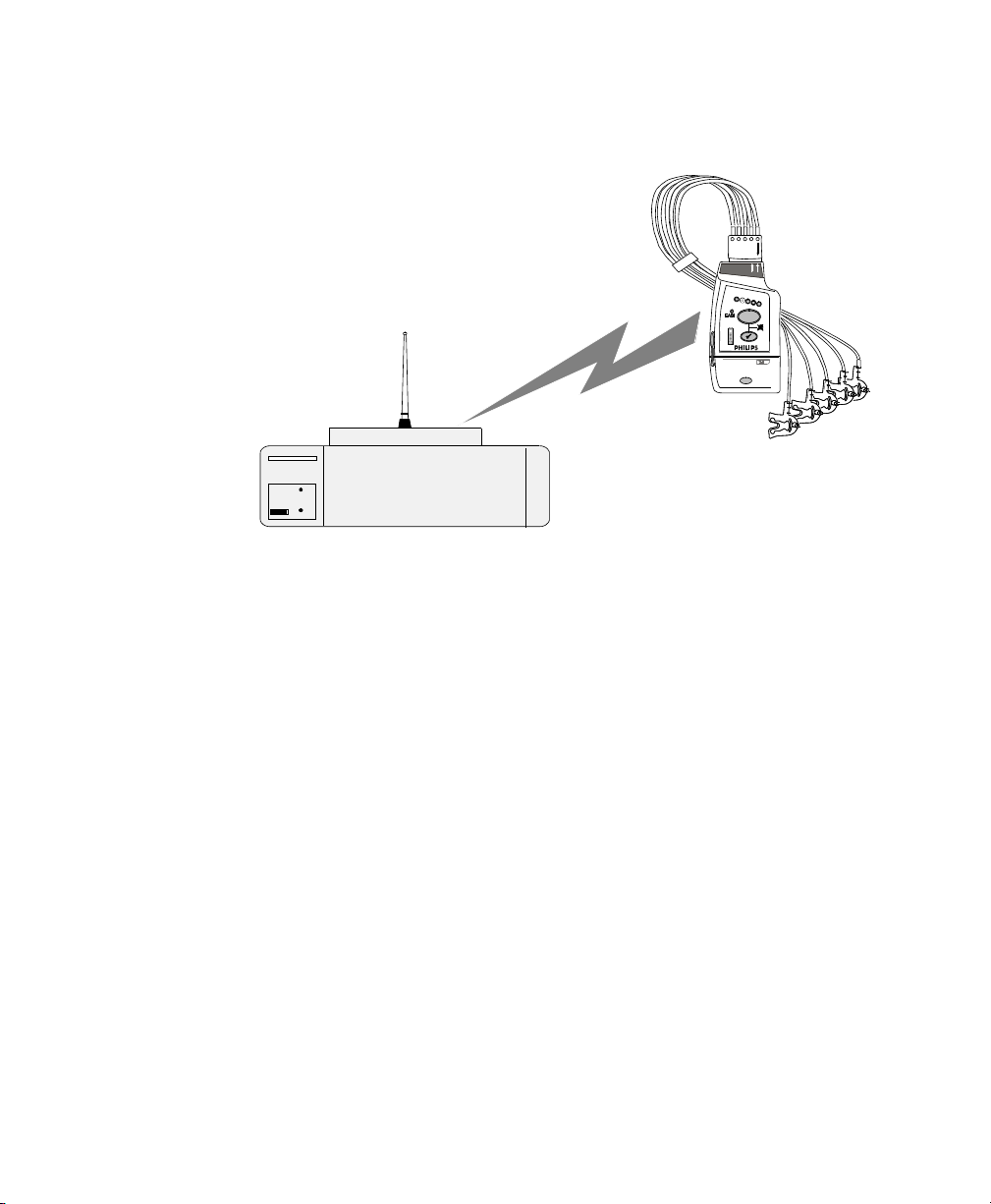
The Philips Telemetry System consists of:
• A transmitter for each patient.
• An antenna system.
• A receiver for each transmitter.
• A mainframe housing up to eight receivers.
System Overview
) and pulse rate, if
2
available.
measurements and waveforms at the
2
patient’s side when connected to the TeleMon Companion Monitor.
Other possible items include:
• The TeleMon Companion Monitor: TeleMon can be used to view
waveforms and heart rate and SpO
numerics as well as measure NBP.
2
For more information see the Philips TeleMon B A02/A03 Companion
Monitor Instructions for Use.
See the Philips Telemetry System Service Guide
or your local trained service
professional for assistance.
Introduction to the Philips Telemetry System
1-7
System Overview
Philips Telemetry System
M2601B
EASI, 3
5
Dual-Band
Operation
The Philips Telemetry System (M2600B) can operate in both the 406-480 MHz
and 590-614 MHz ranges. The exact operating frequency for each transmitter/
receiver pair is set so as to meet specific customer needs, while maintaining
compliance with local and international radio regulations.
For United States operation, the M2600B will operate only in the protected,
dedicated Wireless Medical Telemetry Service (WMTS) band (608-614 MHz).
1-8 Introduction to the Philips Telemetry System

Transmitters
Transmitters
The following Philips transmitters can be used with the Philips Telemetry
System:
• ECG-only transmitter
•ECG/SpO
transmitter
2
Standard and EASI M2601A transmitters can also be used. These transmitters
can operate simultaneously with M2601B transmitters. For operating
information, refer to the Instructions for Use for the Philips Telemetry System
(part number M2600-9001C).
Note—“What’s New” on page 1-2 summarizes the differences between
the M2601B and M2601A transmitters.
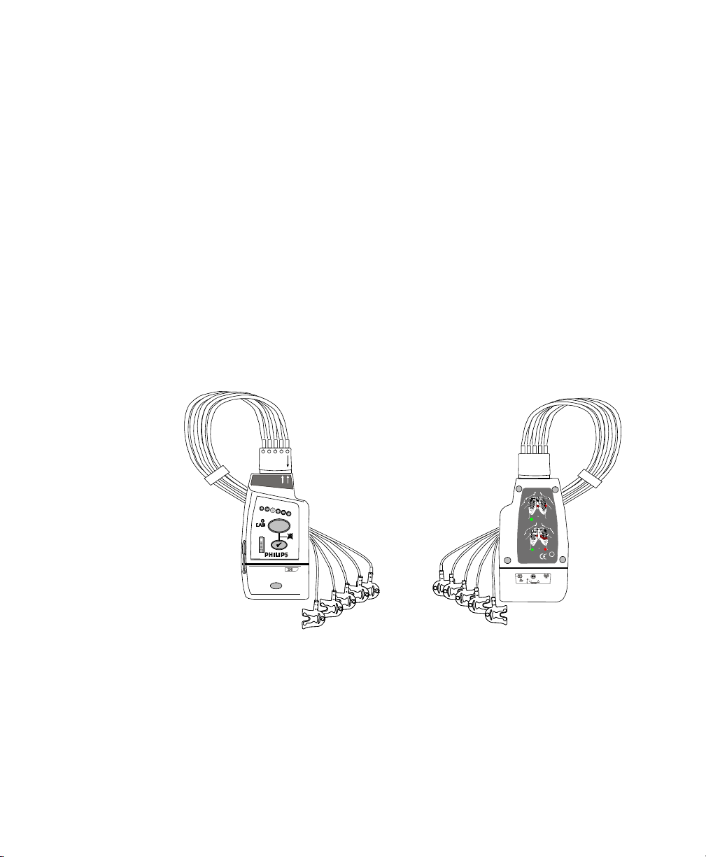
The M2601B Transmitter models are illustrated on the following pages in this
chapter. Subsequent tables describe the controls, indicators, markings, and
audible sounds respectively.
If your hospital uses both the M2601B Transmitter and IntelliVue
TRx devices
The M2601B Transmitter and M4841A TRx Transceiver are similar in
appearance. You can distinguish between them by:
• Name on the front of the device
• Label color (dark gray for M2601B and pale gray for TRx)
Introduction to the Philips Telemetry System
1-9
Transmitters
M2601B Transmitter Features
• Clinician-selectable Standard or EASI leads in same transmitter, at the
bedside.
• Powered by two AA Alkaline batteries.
• Spot Check SpO
•FAST-SpO
without using any control buttons.
2
(Fourier Artifact Suppression Technology) for improved
2
motion artifact rejection and low-perfusion performance.
• Simultaneous operation in system with M2601A Transmitter.
• Two sizes - smaller ECG-only version and larger ECG-SpO
version.
2
• Battery gauge on transmitter.
• Designed to be ergonomic and comfortable for patients to wear.
• Colored labels provide clinical unit identifiers.
• Lead sets are optimized for ambulating patients, with a cable length of
79 cm (30 in).
• Gunk guards prevent dirt from accessing unused ECG and SpO
cable
2
ports and the unused TeleMon/Service port, thus simplifying cleaning.
• New pouches with clear front and flaps.
.
M2601B
EASI, 3
5
EASI
S
A
I
E
Front View
M2601B Transmitter - ECG only
1-10 Introduction to the Philips Telemetry System
FCCID: XXXXXXXX
CANADA IC: XXXX
i
Back View
!
0123
Transmitter
Controls Front
iii
Transmitters
i
ii
a
M2601B
EASI, 3
b
5
1
A
c
B
d
C
2
3
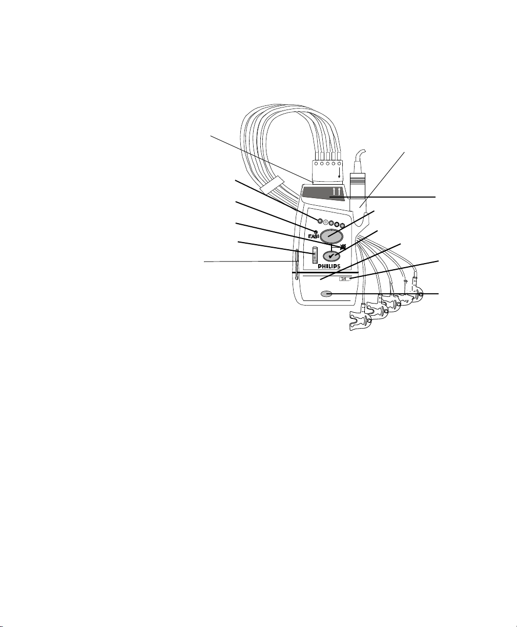
ECG/SpO2 Transmitter - Front View
The labeled items in the diagram above include:
• Transmitter controls (A-C)
• Indicators (a-d)
• Labels (1-3)
• Ports (i-iii)
These items are defined on subsequent tables.
Introduction to the Philips Telemetry System
1-11
Transmitters
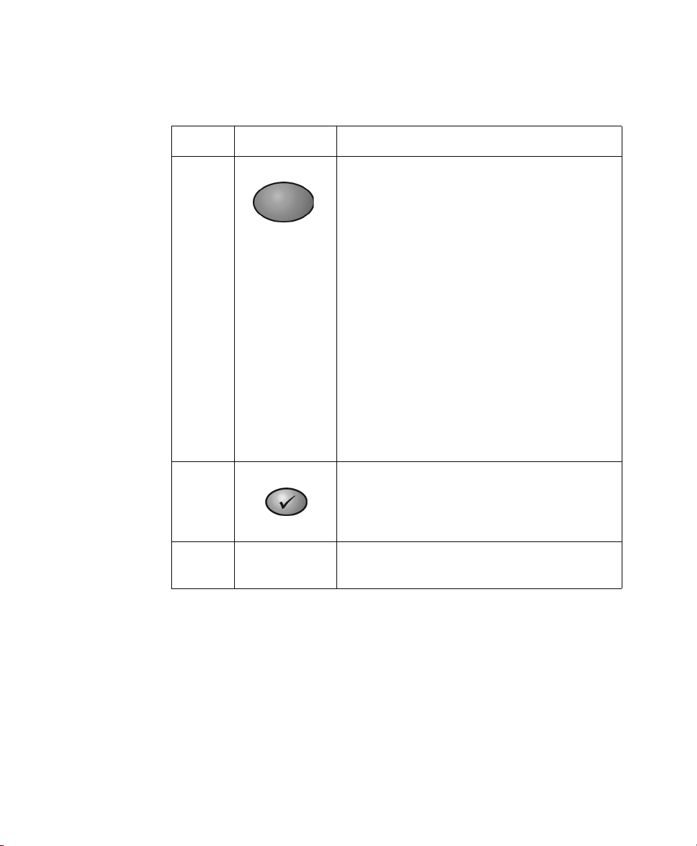
Controls
Callout Control Definition
A
B
C
Telemetry Button: Depending on the
configuration, this multi-function button directs
the Information Center to generate a Nurse Call,
central recording, both, or none.
If desired, you can turn Nurse Call off for
individual patients at the Information Center by
using the Telemetry Setup Window. See
“Turning Nurse Call On/Off” on page 1-23 for
additional information.
Note—Recordings generated by the telemetry
button are stored in Alarm Review at the
Information Center.
Note—If the installation includes a paging
system and if the Information Center is
configured for paging upon receipt of Nurse
Call, a Nurse Page signal will be initiated.
Check Button. Checks the status of the
transmitter. When pressed, the battery gauge,
lead set type, and EASI (if in use) indicators
illuminate.
Power On/Off Battery Compartment. Battery insertion turns
power on; battery removal turns power off.
1-12 Introduction to the Philips Telemetry System
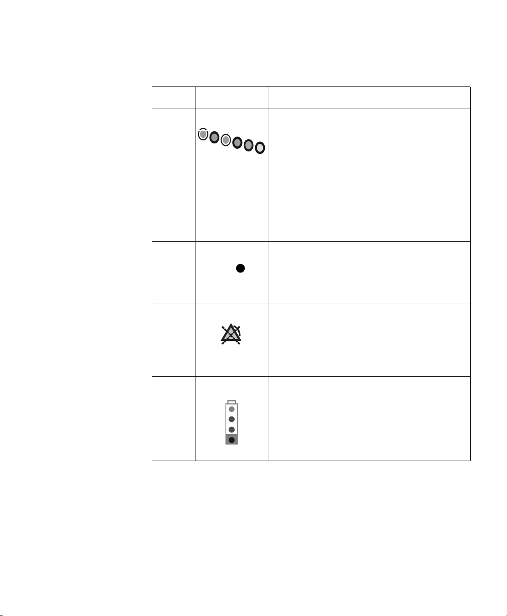
Indicators
Transmitters
Callout Indicator Definition
a
Lead Indicator.
• Lights momentarily to display leads
attached when lead set is inserted or when
the Check button is pressed.
• When a Leads Off condition occurs, the
light(s) indicate the lead(s) that need to be
reapplied. The light(s) remain on until the
Leads Off condition ends.
Note—The 6th indicator (left-most LED) is not
used for the M2601B Transmitter.
b
EASI Indicator. Illuminates momentarily upon
insertion of lead set in EASI position. Lit by
Check button when EASI is in use.
EASI
c
d
Alarms Pause/Suspend Indicator. Inactive.
Note—If the transmitter is connected to the
TeleMon Companion Monitor this indicator is
lit during 3 minute alarm pause period initiated
at TeleMon.
Battery Gauge. When the Check button is
pressed, indicates the amount of power
remaining in the batteries. Valid only for
recommended battery type.
Note—See “Checking the Battery Power Level”
on page 1-32.
Introduction to the Philips Telemetry System
1-13
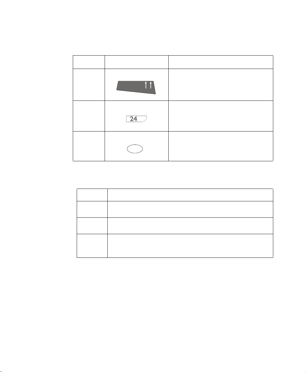
Transmitters
Front Labels
Callout Label Definition
Ports
1
M2601B
EASI, 3
5
2
3
Lead Set Insertion Guide. See
“Connecting the ECG Cable” on page 3-
14.
Device Identification Label
Unit Identification Label. (one of
seven colors). Color-coded sticker.
Callout Definition
i ECG Lead Set Port. Connection for 3-wire or 5-wire lead set.
ii SpO
Sensor Port. Connection for SpO2 sensor.
2
iii TeleMon/Service Port. Connection for cable to TeleMon
Companion Monitor or to Service Tool.
1-14 Introduction to the Philips Telemetry System
 Loading...