

Philips Medical Systems North America 4843B Users Manual
IntelliVue Telemetry System
DRAFT-3
1.4 GHz Core Access Point/Remote Antenna
Installation Guide
p
o
w
N
A
e
e
c
r
R
t
/
w
t
L
S
a
i
v
i
o
d
y
n
i
rk
t
n
i
k
y
o
c
Serial Service Port
5VCD
10/100 48 VDC
IOIOI
2
2
IOIOI
Remote
Antenna
C
ore
Access Point
Remote
Antenna
Part Number: 453564238171
Printed in the U.S.A.
June, 2011
First Edition
*453564238171*

Proprietary Information
DRAFT-3
This document contains proprietary information that is protected by copyright.
C
opyright
Copyright © 2011 Koninklijke Philips Electronics N.V. All Rights Reserved.
M
anufacturer
Philips Medical Systems
3000 Minuteman Road
Andover, MA 01810-1099
(+1) 978-687-1501
This document was printed in the United States of America.
T
rademark Acknowledgements
HP is a registered trademark of Hewlett-Packard Company
Cisco is a registered trademark of Cisco Systems
All other trademarks, trade names and company names referenced herein are used for identification purposes only and are
the property of their respective owners.
F
CC Notice
This device complies with part 15 of the FCC Rules. Operation is subject to the following two conditions: (1) these devices may
not cause harmful interference, and (2) these devices must accept any interference received, including interference that
may cause undesired operation.
Pursuant to Part 15.21 of the FCC Rules, any changes or modifications to this equipment not expressly approved by Philips
Medical Systems may cause harmful radio frequency interference, and void your authority to operate this equipment.
Operation of this equipment in the United States requires the prior coordination with a frequency coordinator designated by
the Federal Communications Commission (FCC) for Wireless Medical Telemetry Service.
W
arranty
The information contained in this document is subject to change without notice. Philips Medical Systems makes no warranty
of any kind with regard to this material, including, but not limited to, the implied warranties or merchantability and fitness for
a particular purpose. Philips Medical Systems shall not be liable for errors contained herein or for incidental or consequential
damages in connection with the furnishing, performance, or use of this material.
P
rinting History
New editions of this document will incorporate all material updated since the previous edition. The documentation printing
date and part number indicate its current edition. The printing date and edition number change when a new edition is
printed. The document part number changes when extensive technical changes are incorporated.
First Edition ........................................................................................................................................................................June, 2011
ii

Contents
DRAFT-3
About This Guide
Audience. . . . . . . . . . . . . . . . . . . . . . . . . . . . . . . . . . . . . . . . . . . . . . . . . . . . . . . . . . . .vi
Document Organization . . . . . . . . . . . . . . . . . . . . . . . . . . . . . . . . . . . . . . . . . . . . . . .vi
Notational Conventions. . . . . . . . . . . . . . . . . . . . . . . . . . . . . . . . . . . . . . . . . . . . . . . .vi
Related Documentation . . . . . . . . . . . . . . . . . . . . . . . . . . . . . . . . . . . . . . . . . . . . . . vii
Terminology . . . . . . . . . . . . . . . . . . . . . . . . . . . . . . . . . . . . . . . . . . . . . . . . . . . . . . . . vii
Chapter 1: Overview
Introduction . . . . . . . . . . . . . . . . . . . . . . . . . . . . . . . . . . . . . . . . . . . . . . . . . . . . . . . 1-2
A General Description of the ITS Core Access Point . . . . . . . . . . . . . . . . . . . . . . . 1-3
Core AP Mounting Options . . . . . . . . . . . . . . . . . . . . . . . . . . . . . . . . . . . . . . . . 1-4
Power Source . . . . . . . . . . . . . . . . . . . . . . . . . . . . . . . . . . . . . . . . . . . . . . . . . . 1-4
Synchronization Signal . . . . . . . . . . . . . . . . . . . . . . . . . . . . . . . . . . . . . . . . . . . 1-4
Transceiver Mobility . . . . . . . . . . . . . . . . . . . . . . . . . . . . . . . . . . . . . . . . . . . . . 1-4
Technical Alarms . . . . . . . . . . . . . . . . . . . . . . . . . . . . . . . . . . . . . . . . . . . . . . . . 1-5
Firmware Updates. . . . . . . . . . . . . . . . . . . . . . . . . . . . . . . . . . . . . . . . . . . . . . . 1-5
Management Interfaces . . . . . . . . . . . . . . . . . . . . . . . . . . . . . . . . . . . . . . . . . . 1-5
Connectors and Status Indicators . . . . . . . . . . . . . . . . . . . . . . . . . . . . . . . . . . . . . 1-6
ITS Core AP Connectors . . . . . . . . . . . . . . . . . . . . . . . . . . . . . . . . . . . . . . . . . . 1-6
Remote AP Connectors. . . . . . . . . . . . . . . . . . . . . . . . . . . . . . . . . . . . . . . . . . . 1-7
ITS Core AP Status LEDs. . . . . . . . . . . . . . . . . . . . . . . . . . . . . . . . . . . . . . . . . . 1-8
Remote Antenna Status LEDs . . . . . . . . . . . . . . . . . . . . . . . . . . . . . . . . . . . . . 1-8
Specifications. . . . . . . . . . . . . . . . . . . . . . . . . . . . . . . . . . . . . . . . . . . . . . . . . . . . . . 1-9
Ordering Information . . . . . . . . . . . . . . . . . . . . . . . . . . . . . . . . . . . . . . . . . . . . . . . 1-11
Chapter 2: Installing the ITS 1.4 GHz Core Access Point
Access Point Placement Guidelines . . . . . . . . . . . . . . . . . . . . . . . . . . . . . . . . . . . . 2-2
General Installation Procedure. . . . . . . . . . . . . . . . . . . . . . . . . . . . . . . . . . . . . . . . 2-3
Mounting the ITS Core AP to a Wall (Fixed Mount) . . . . . . . . . . . . . . . . . . . . . . . . 2-6
Mounting the ITS Core AP to a Wall (CA Earthquake Rated) . . . . . . . . . . . . . . . . 2-7
Mounting the ITS Core AP Above a Ceiling Tile . . . . . . . . . . . . . . . . . . . . . . . . . . . 2-9
Mounting the ITS Core AP Below a Ceiling Tile (Fixed Mount) . . . . . . . . . . . . . . 2-12
Mounting the ITS Core AP Below a Ceiling Tile (Quick Release) . . . . . . . . . . . . 2-16
Mounting the ITS Remote Antenna to a Wall (Fixed Mount) . . . . . . . . . . . . . . . 2-21
IntelliVue Telemetry System 1.4 GHz Core Access Point/Remote Antenna Installation Guide iii
Mounting the ITS Remote Antenna to a Wall (CA Earthquake Rated) . . . . . . . . 2-22
Mounting the ITS Remote Antenna Above a Ceiling Tile (Mounting Rails) . . . . 2-23

Contents
DRAFT-3
Mounting the ITS Remote Antenna Above a Ceiling Tile (Tether Mount). . . . . . 2-26
Mounting the ITS Remote Antenna Below a Ceiling Tile (Fixed Mount). . . . . . . 2-28
Mounting the ITS RA Below a Ceiling Tile (Quick Release) . . . . . . . . . . . . . . . . . 2-32
AP Configuration Information . . . . . . . . . . . . . . . . . . . . . . . . . . . . . . . . . . . . . . . . 2-35
Access Point Startup Sequence . . . . . . . . . . . . . . . . . . . . . . . . . . . . . . . . . . . . . . 2-35
Chapter 3: Maintaining the ITS 1.4 GHz Core Access Point
Maintenance Procedure . . . . . . . . . . . . . . . . . . . . . . . . . . . . . . . . . . . . . . . . . . . . . 3-2
Troubleshooting the Core AP Using its LEDs . . . . . . . . . . . . . . . . . . . . . . . . . . . . . 3-2
Troubleshooting the Remote Antenna Using its LEDs . . . . . . . . . . . . . . . . . . . . . 3-3
Replacing a Core AP or Remote Antenna. . . . . . . . . . . . . . . . . . . . . . . . . . . . . . . . 3-4
Ordering Replacement Parts. . . . . . . . . . . . . . . . . . . . . . . . . . . . . . . . . . . . . . . . . . 3-4
iv

About This Guide
DRAFT-3
This IntelliVue Telemetry System 1.4 GHz Core Access Point/Remote
Antenna Installation Guide provides complete instructions and procedures
for installing the Philips IntelliVue Telemetry System ITS4843B 1.4 GHz
Core Access Point and ITS4846A Remote Antennas. This section
describes the document and includes:
• Audience
• Document Organization
• Notational Conventions
• Related Documentation
• Terminology
IntelliVue Telemetry System 1.4 GHz Core Access Point/Remote Antenna Installation Guide v

About This Guide
DRAFT-3
Audience
The IntelliVue Telemetry System 1.4 GHz Core Access Point/Remote
Antenna Installation Guide is written for trained service personnel who will
install the IntelliVue Telemetry System 1.4 GHz Core Access Point as part
of an overall IntelliVue Telemetry System deployment.
Document Organization
The information in this guide is organized and presented as follows:
• Chapter 1, Overview, describes the Model ITS4843B IntelliVue
• Chapter 2, Installing the ITS 1.4 GHz Access Point, provides
Telemetry System 1.4 GHz Core Access Point and how it is used to
provide a bi-directional data flow between the IntelliVue Information
Center and patient-worn transceivers and wireless bedside monitors.
procedures to physically install the Philips IntelliVue Telemetry System
1.4 GHz Core Access Point and includes instructions for mounting the
Core AP and Remote Antennas to a wall, above a ceiling tile, and below
a ceiling tile.
• Chapter 3, Maintaining the ITS 1.4 GHz Core Access Point, provides
Notational Conventions
This guide uses the following notational conventions to convey
information:
Note
Caution Cautionary statements call attention to a condition that could result in loss
Warning
Notes call attention to important information.
of data or damage to equipment.
Warnings call attention to a condition that could result in physical injury.
procedures to maintain and troubleshoot operation of the Philips
IntelliVue Telemetry System 1.4 GHz Core Access Point.
vi

Related Documentation
DRAFT-3
Please refer to these other documents for additional installation service
information about the IntelliVue Telemetry System:
• ITS Access Point Controller Installation Guide (453564238151) -
• ITS 2.4 GHz Access Point Installation Guide (453564238161) - gives
• ITS Infrastructure Installation and Service Guide (453564238181) -
• ITS Sync Unit Installation Guide (453564238191) - lists procedures to
• Upgrading ITS Access Point Controllers and Access Points
About This Guide
provides procedures to physically install and power the ITS Access
Point Controller at the clinical site.
procedures to install the model ITS4852A 2.4 GHz AP at the clinical
site to a wall, or above or below a ceiling tile.
provides complete information and procedures to install, configure,
inter-connect, and deploy the ITS infrastructure at the clinical site. This
document includes site planning guidelines, procedures for use of the
APC command line and graphical user interfaces, AP configuration
procedures, and APC and AP firmware deployment procedures.
install the model M4844A Sync Unit at the clinical site.
(453564238141) - gives procedures to use the Philips ITS APC and AP
Upgrade Wizard tool to install and synchronize the firmware version on
ITS APCs and APs.
Terminology
Please note the following terms, acronyms, and abbreviations used
throughout this document:
• IntelliVue Clinical Network (ICN) - This term refers to the entire Philips
network. In a routed topology, the ICN includes the routers and all
inter-connected Database Domain(s) and the IntelliVue Telemetry
System wireless subnet.
atabase Domain (DBSD) - This term is used to describe the
• D
“network” that contains the Standalone IntelliVue Information Center,
or the IntelliVue Database Server and its connected Information
Centers, Clients, bedsides, and infrastructure. This term applies to
both routed and non-routed topologies.
IntelliVue Telemetry System 1.4 GHz Core Access Point/Remote Antenna Installation Guide vii

About This Guide
DRAFT-3
• IntelliVue Telemetry System (ITS) - Cellular wireless architecture that
provides two-way communications between patient-worn transceivers,
wireless bedside patient monitors, and the IntelliVue Information
Center.
ntelliVue Wireless Subnet - This term is used to describe the IntelliVue
• I
Telemetry System (ITS) “network” that contains the infrastructure
used in a routed topology to connect the IntelliVue Telemetry System
devices.
ccess Point (AP) - A network device that provides bi-directional
• A
wireless access to the monitoring network for patient-worn
transceivers and wireless bedside monitors.
• A
ccess Point Controller (APC) - A network device used to manage the
operation of the Access Points. One APC is elected the Master APC.
The Master APC supports the web interface to the system and
manages the master configuration.
ccess Point Group/AP Group - A logical grouping of APs. AP members
• A
of the same AP Group will inherit common configuration settings
(defaults). AP groups will often map logically to the clinical units in
which the ITS is being installed.
• P
artnered APC - Configurable element within an AP Group used to
determine which APC will manage the operation of the AP members of
a particular AP Group.
F Access Code - Configurable element in the Smart-hopping AP
• R
defaults shared among APs and patient-worn transceivers to control
wireless access to the monitoring network. Portable devices will only
connect to access points with which they share access codes. The RF
Access Code allows a specific wireless client that is programmed with
a matching Access Point RF Access Code to connect to that Access
Point.
ynchronization Unit - The Philips Sync Unit provides a necessary
• S
common clock signal to synchronize all the IntelliVue Access Points in
the system. As patients ambulate around the hospital coverage area
their transmitted data are handed over from one AP to another
seamlessly without interruption or data loss.
ystem ID - Configurable element in the APC Configuration to logically
• S
associate Access Points and Access Point Controllers operating within
the same ITS.
viii

1
Overview
DRAFT-3
This chapter provides a high-level overview of the Philips IntelliVue
Telemetry System ITS4843B 1.4 GHz Core Access Point and includes:
• Introduction
• A General Description of the ITS Core Access Point
• Connectors and Status Indicators
• Specifications
• Ordering Information
IntelliVue Telemetry System 1.4 GHz Core Access Point/Remote Antenna Installation Guide 1-1
Chapter 1: Overview
DRAFT-3
Introduction
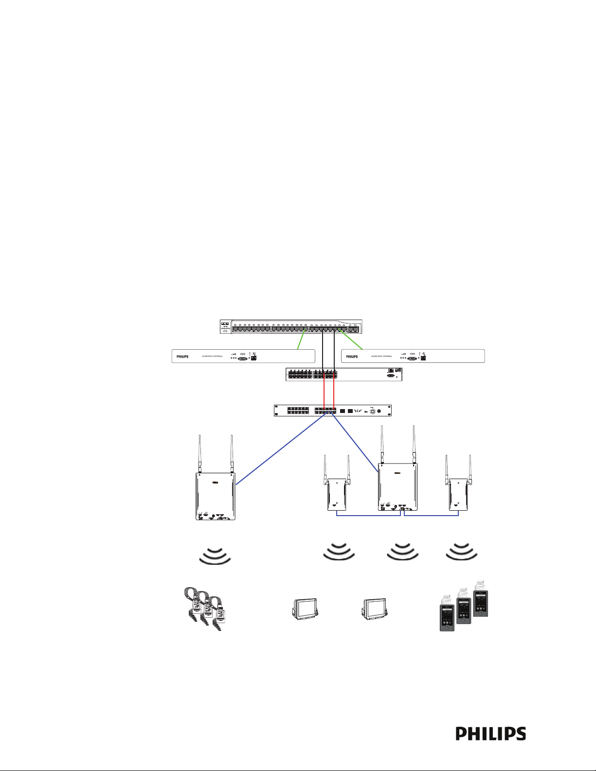
The Philips IntelliVue Telemetry System (ITS) uses a cellular wireless architecture to
provide two-way communications between patient-worn transceivers/monitors and
wireless bedside patient monitors, and the IntelliVue Information Center.
Using the “Smart-hopping” wireless protocol, the ITS provides monitoring
capabilities for ambulatory patients within a wide coverage area. The ITS
transceivers (portable patient-worn devices), patient-worn monitors, wireless
bedside monitors, and infrastructure operate on the 1.4 GHz US Wireless Medical
Telemetry Service (WMTS) band or on the 2.4 GHz Industrial, Scientific and Medical
(ISM) band.
The pocket-size patient-worn transceiver or monitor sends patient data, and sends
and receives control and device information to and from the IntelliVue Information
Center (bi-directional communication) for subsequent monitoring, display, analysis,
alarm detection, operator alerts, data storage and permanent recording. Displays,
settings, recordings, and alarms are controlled from the IntelliVue Information
Center. Recordings can also be initiated from the patient worn-transceivers/
monitors.
Access Point Controller
1.4 GHz Smart-hopping
Access Points
1.4 GHz
Core Access Point
ICN Network Switch
Access Point Controller
Power over Ethernet Unit
Synchronization Unit
1.4 GHz
Remote Antenna
1.4 GHz
Core Access Point
1-2
1.4 GHz Patient-worn
Transceivers
1.4 GHz Wireless
Bedside Monitors
Figure 1-1: 1.4 GHz IntelliVue Telemetry System
1.4 GHz Patient-worn
Monitors
A General Description of the ITS Core Access Point
DRAFT-3
You can configure the Access Point Controller to communicate with IntelliVue 1.4 or
2.4 GHz Smart-hopping Access Points (APs). IntelliVue 1.4 GHz APs can only
communicate with 1.4 GHz transceivers and monitors. Likewise, 2.4 GHz APs can
only communicate with 2.4 GHz transceivers and monitors. You cannot mix 1.4 GHz
and 2.4 GHz transceivers or monitors at a given ITS installation site.
Philips Smart-hopping technology utilizes a cognitive radio that senses the RF
environment and adapts to it. Dynamic wireless channel allocation ensures best
use of available wireless spectrum. When configured to operate in the 2.4 GHz
spectrum, the ITS is designed to co-exist with other 802.11 wireless deployments.
A General Description of the ITS Core Access Point
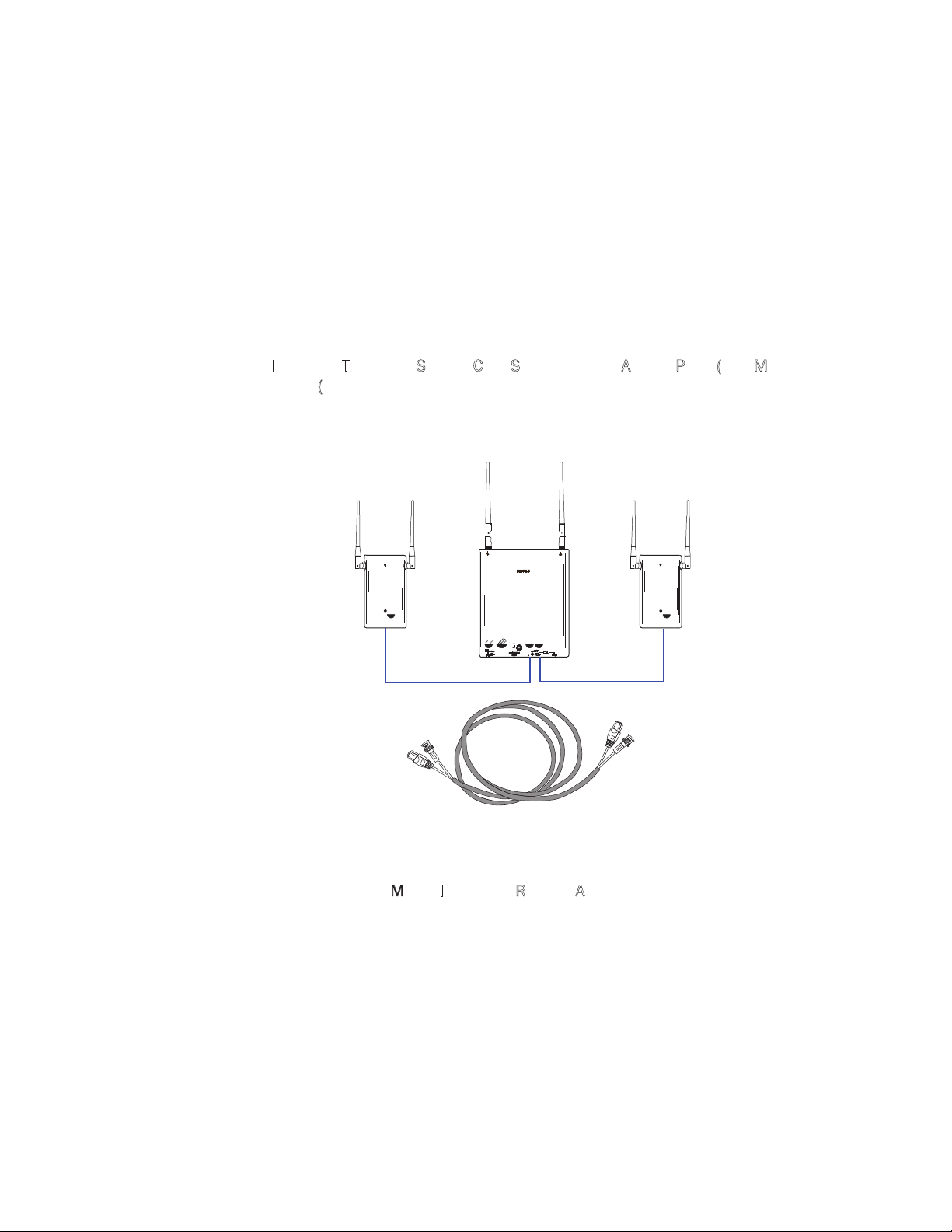
he IntelliVue Telemetry System Core Smart-hopping Access Point (AP), Model
T
I
TS4843B (Figure 1-2), provides an air-link to transmit and receive data between
ITS wireless clients and the Philips IntelliVue Information Center via the ITS
infrastructure.
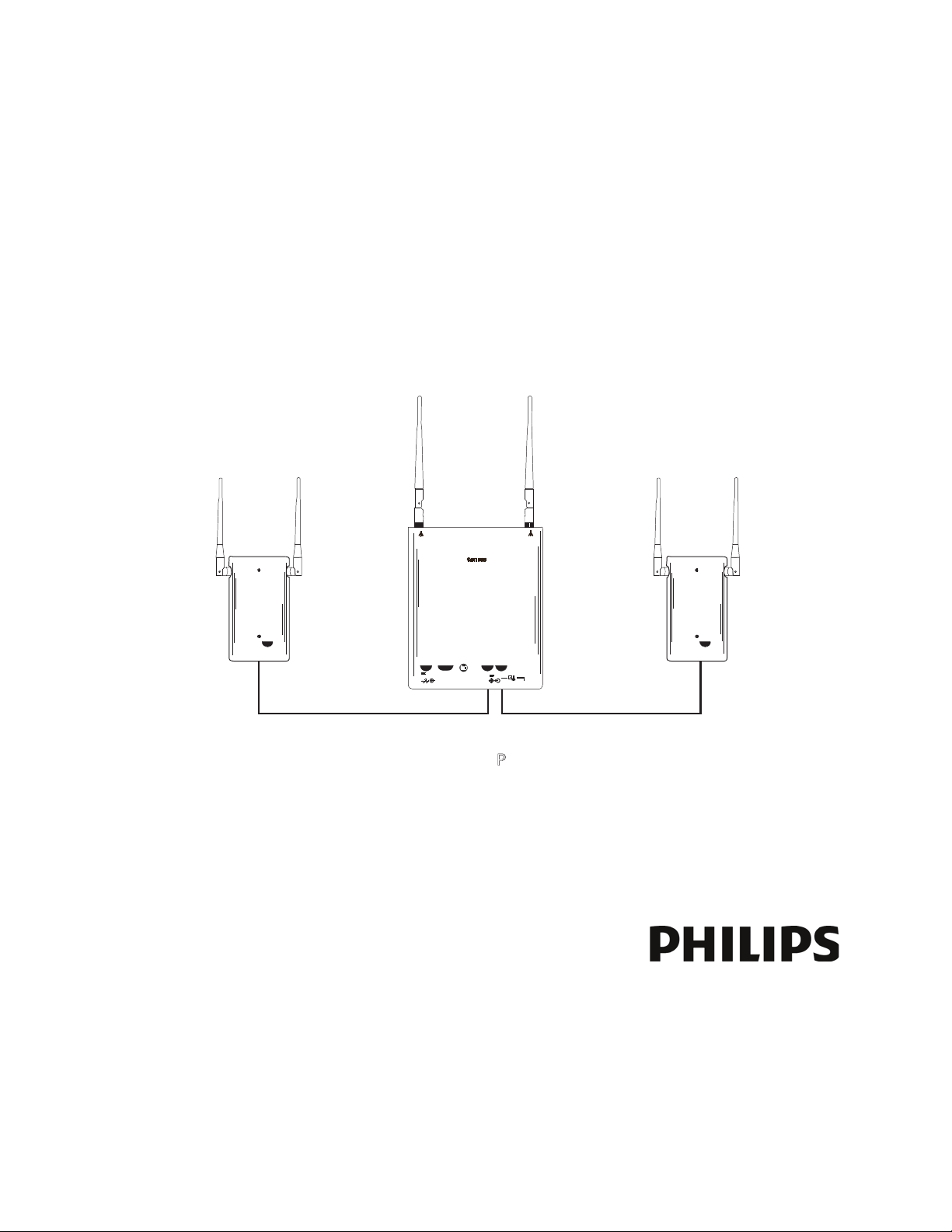
Core AP
Remote
Antenna
74 ft. Coax and
UTP Cable Bundle
Figure 1-2: IntelliVue Telemetry System Core Access Point
Remote
Antenna
The Core AP is a modular antenna infrastructure consisting of a Core AP (CAP) with
up to two connected M
odel ITS4846A Remote Antennas (RAs). A 74-foot (22.6 m)
coaxial and unshielded twisted pair (UTP) cable bundle is used to connect a Remote
Antenna to a Core AP. Core APs are only available for the 1.4 GHz ITS.
The effective range of the Core AP and of each Remote Antenna is typically 32 feet.
The Core AP always supports a maximum of 18 wireless clients (i.e., patient-worn
transceivers or bedside monitors) regardless of its component configuration. A Core
AP alone supports 18 wireless clients. When used with a single RA, the Core AP
supports nine wireless clients and its connected RA supports nine wireless clients
(9+9=18). When used with two RAs, the Core AP supports six wireless clients and
its connected RAs each support six wireless clients (6+6+6=18).
IntelliVue Telemetry System 1.4 GHz Core Access Point/Remote Antenna Installation Guide 1-
3

Chapter 1: Overview
DRAFT-3
When monitored patients are ambulatory, data roaming is handled seamlessly
between the other IntelliVue Access Points in the system. The Core AP and each RA
are always used with their two supplied antennas installed. The Core AP and its
attached Remote Antennas can be mounted out of the way on corridor walls, or
above or below ceiling tiles.
Philips provides Model ITS4843B ITS Core Access Points for the 1.4 GHz US
Wireless Medical Telemetry Service (WMTS) band (P/N 989803171211) that can
be used with one or two Model ITS4846A Remote Antennas (P/N 865052).
Core AP Mounting Options
Wall-mounting hardware is standard. An optional above/below ceiling tile mount kit
(P/N 862415 Option K05 (453564052201)) is available that can be used with both
the Core AP and its Remote Antennas.
Power Source
The ITS 1.4 GHz Core Access Point receives its 48 VDC operating power source via
its Ethernet LAN cabling from the ITS Power over Ethernet Unit via the ITS Sync Unit.
The AP is not equipped with a power socket. The AP consumes less than 13.8W, and
internally generates a variety of voltages used for its internal components.
The CAT-5 UTP cable within the 74 ft.-cable bundle carries 5.5 VDC power, Transmit
and Receive control signals, and Antenna Diversity signals from the Core AP to a
connected Remote Antenna.
The 75 Ohm coaxial cable within the 74 ft.-cable bundle carries RF and DC sense
signals from the Core AP to a connected Remote Antenna.
Synchronization Signal
The ITS 1.4 GHz Core Access Point receives a synchronization signal from a network
of Sync Units that enables a patient-worn transceiver to hand over data seamlessly
between APs within the coverage area when a patient is ambulatory and to transfer
data to the IntelliVue Information Center without interruption. Each Sync Unit
provides synchronization for up to 12 APs. The Sync Unit also distributes the
common reference clock signal needed by the IntelliVue Telemetry System as a
whole.
Transceiver Mobility
The Philips IntelliVue Telemetry System supports full mobility of patient-worn
transceivers within the area of coverage. This roaming is accomplished via
communications between the transceivers and the Access Points (AP) as follows.
As a patient-worn transceiver is moved around a building, it automatically monitors
the quality of the wireless link to its current AP (and it also detects the presence of
other APs). When the quality starts to deteriorate, the transceiver automatically
establishes a new connection to another AP.
1-4
The patient-worn transceiver remains connected to two APs for a finite time, and
thus the same data is received by these APs. During this time, information for
header compression and other data for the connection is routed to the new AP.

A General Description of the ITS Core Access Point
DRAFT-3
One of the two APs subsequently releases the radio connection. If a packet is in
progress when a handover occurs, then the packet is reassembled co-operatively
between the two APs.
The central station or other ICN central equipment sees an unbroken flow of
complete IP packets.
Technical Alarms
Each AP is configured to signal alarm conditions that are viewed at the IIC in the
wireless status log.
The IntelliVue Access Point is configured to raise alarms on error conditions. The
alarms are sent over the ITS/ICN Ethernet LAN infrastructure to a monitoring station
or Database Sever. The Access Point raises an alarm if:
• it is approaching its maximum load capacity
• if data loss exceeds the configured threshold
• it loses its synchronization signal
For small systems having only one AP and no Sync Unit, the AP can be configured to
suppress the loss of synchronization signal alarm.
Note that the ITS APC provides System Alarms such as loss of synchronization, high
data loss, AP hardware failure, and over capacity. Additionally, when redundant
APCs are installed, the APC will provide a System Alarm for APC hardware or
software failure.
Firmware Updates
You can update the firmware on the ITS 1.4 GHz Core Access Point from the Access
Point Controller by using the Philips Animation Upgrade Wizard. Refer to the service
document entitled IntelliVue Telemetry System Infrastructure Installation and
Service Guide (M3185-91934) for details. The AP firmware image is provided on the
Philips Network Infrastructure Tools CD-ROM.
Management Interfaces
The Access Point supports the full range of management interfaces via the Philips
Access Point Controller (APC). These interfaces also enable you to view the status of
the Access Point including the following information:
• System configuration such as firmware version
• Connection information such as numbers of packets received and transmitted,
and number of errors
• Wave data information such as total number of seconds of data sent and lost
The AP statistics can be read by remote devices (e.g., an ICN Database Server),
using the Scaleable Node Address Protocol (SNAP).
The following status items can be displayed using the APC’s web-accessed graphical
user interface:
• AP Name
• Physical Address
• Partnered AP Controller
IntelliVue Telemetry System 1.4 GHz Core Access Point/Remote Antenna Installation Guide 1-
5
Chapter 1: Overview
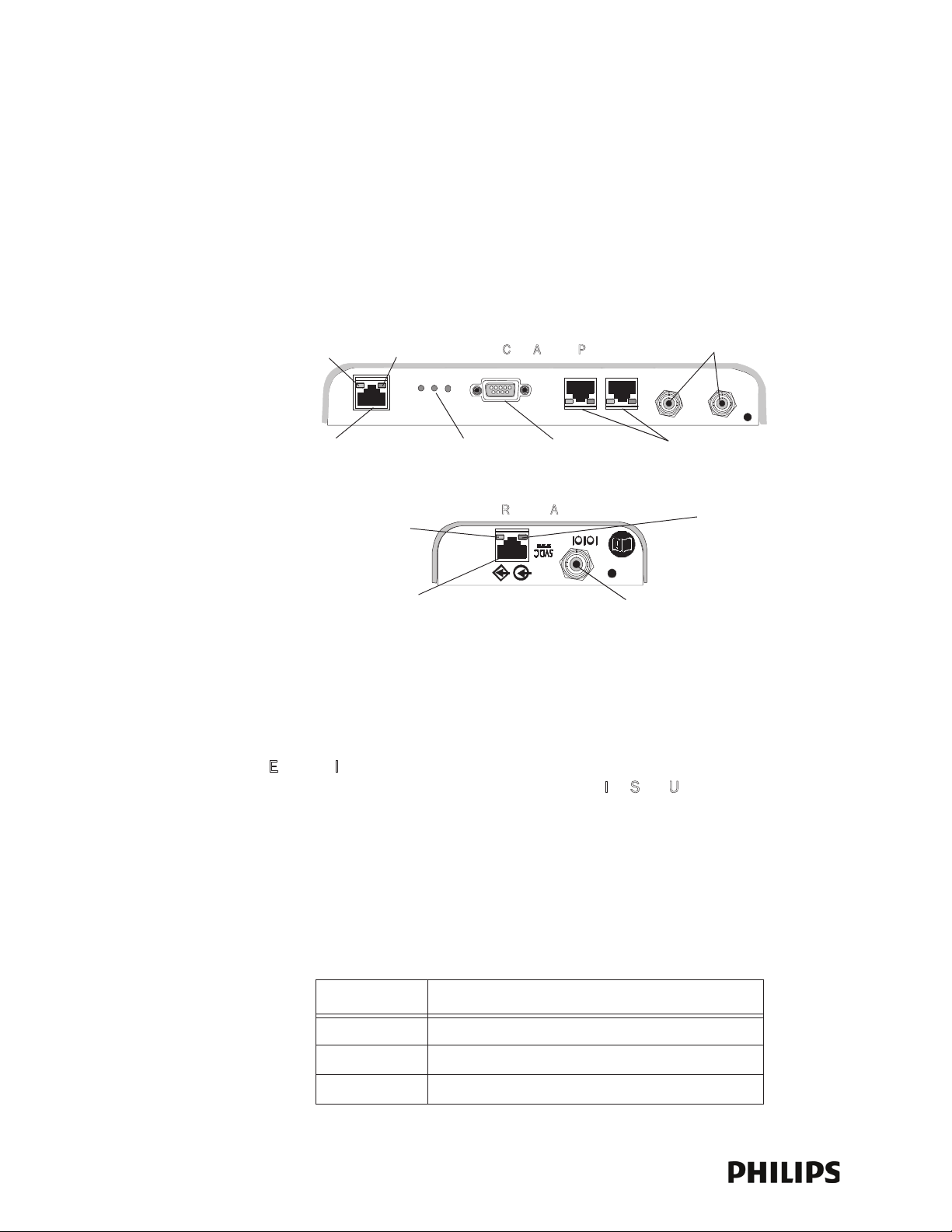
Ethernet Interface to
ITS Sync Unit
I
TS Core Access Point
ITS Remote Antenna
Power/Sync, Radio,
and Network
Status LEDs
Serial Port
UTP Cable Connectors
to Remote Antennas (1 & 2)
with RA Status LEDs
Coaxial Cable Connector
to ITS Core Access Point
Coaxial Cable Connectors
to Remote Antennas (1 & 2)
UTP Cable Connector
to ITS Core AP
Link LED
Activity LED
Connection LED
(Green)
Power LED
(Yellow)
DRAFT-3
• IP Address
• Subnet Mask
• Default Gateway
• AP Type
Connectors and Status Indicators
Figure 1-3 shows the controls and connectors on the 1.4 GHz ITS Core AP and
Remote Antenna.
ITS Core AP Connectors
Note the following connectors on the ITS Core AP:
• Ethernet Interface - The AP provides a 100 Base-T Ethernet interface with an
Figure 1-3: 1.4 GHz ITS Core AP and Remote Antenna Controls and Connectors
RJ-45 connector to connect the Core AP to the I
TS Sync Unit.
The AP Ethernet interface provides data communications to and from the
IntelliVue Information Center over the ITS LAN infrastructure. It also presents
the 48Vdc power and synchronization signals required by the Core AP. The
synchronization signal is superimposed on the power supply voltage. You should
attach a ferrite block to the CAT 5 cabling (from the Sync Unit) no more than 20
inches (50 cm) from the RJ-45 connector to reduce electromagnetic (radiation)
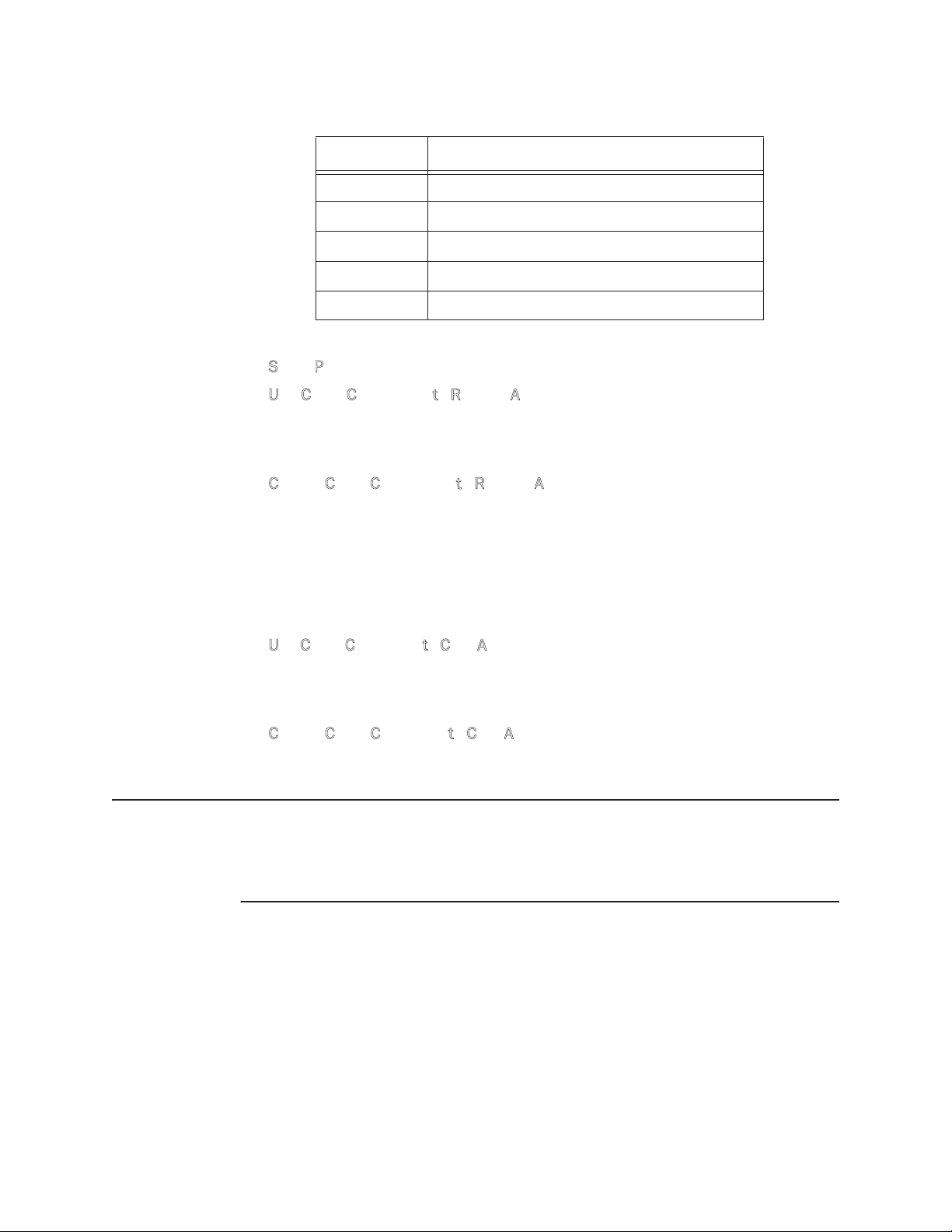
interference. Table 1-1 lists the pin signals for the AP Ethernet interface.
Table 1-1: AP Ethernet Interface Pin Signals
Pin Signal Description
1 Transmit Pair TX + Conductor
2 Transmit Pair TX - Conductor
3 Receive Pair RX + Conductor
1-6
Connectors and Status Indicators
DRAFT-3
Table 1-1: AP Ethernet Interface Pin Signals
Pin Signal Description
4 + 48Vdc Power and Synchronization
5 + 48Vdc Power and Synchronization
6 Receive Pair RX - Conductor
7 0V Power Return
8 0V Power Return
• Serial Port - The serial port is used only for manufacturing purposes.
TP Cable Connectors to Remote Antennas - Two standard RJ-45 connectors
• U
are provided for the UTP cables that connect the Core AP to its Remote
Antennas.Each UTP cable carries 5.5 VDC power, Transmit, Receive and
Antenna Diversity Control signals to the Remote Antenna.
oaxial Cable Connectors to Remote Antennas - Two standard 75 Ohm
• C
connectors are provided for the coaxial cables that connect the Core AP to its
Remote Antennas. Each coaxial cable carries RF and DC sense signals from the
Remote Antenna.
Remote AP Connectors
Note the following connectors on the Remote Antenna:
• U
TP Cable Connector to Core AP - A standard RJ-45 connector is provided for the
UTP cable that connect the Remote Antenna to its Core AP. The UTP cable
carries 5.5 VDC power, Transmit, Receive and Antenna Diversity Control signals
to the Remote Antenna.
oaxial Cable Connector to Core AP - A standard 75 Ohm connector is provided
• C
for the coaxial cable that connects the Remote Antenna to its Core AP. The
coaxial cable carries RF and DC sense signals from the Core AP.
Note If an installed, powered Remote Antenna becomes disconnected from its Core AP
via its Coax/UTP cable bundle, you must reconnect the Coax/UTP cable bundle to
the RA and Core AP, and then cycle power to the connected Core AP before the RA
will re-establish communications with the Core AP.
IntelliVue Telemetry System 1.4 GHz Core Access Point/Remote Antenna Installation Guide 1-
7
Chapter 1: Overview
DRAFT-3
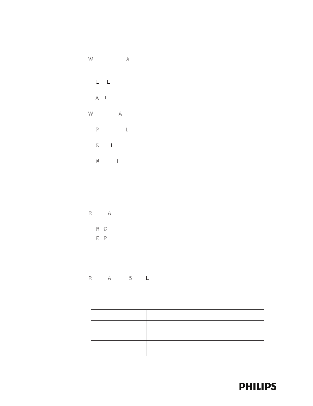
ITS Core AP Status LEDs
The ITS Core AP provides the following status LEDs.
• W
ired/Ethernet Activity - The Core AP provides two LEDs to indicate wired/
Ethernet activity to the ITS infrastructure. During normal operation, these LEDs
indicate the following information:
ink LED - Link present/Ethernet connection. Lights GREEN (ON) when a
- L
pass-through link is present - OFF when not present.
ct LED - Wired network activity. Flashes YELLOW (ON) when there is activity
- A
is over the wired network.
• W
ireless/RF Activity - The Core AP provides three LEDs to indicate wireless/RF
activity. During normal operation, these LEDs indicate the following information:
ower/Sync LED - GREEN (ON) when power and synchronization signal is
- P
present.
adio LED - Normally OFF (not lit) - flashes green to indicate wireless network
- R
activity.
- N
etwork LED - Normally OFF (not lit) - flashes green to indicate wired network
activity.
At initial power on the AP runs a Power On Self-Test (POST). During the POST, the
above LEDs indicators flicker and then all three will illuminate continuously
(AMBER) to indicate correct startup operation. Then, the Power ON LED will
illuminate (GREEN) continuously to indicate that the 48Vdc power and sync
signal are being supplied, and the other two (AMBER) LEDs turn off (not lit).
emote Antenna - The Core AP provides two LEDs on each RJ-45 UTP cable
• R
connector that provides status on a connected Remote Antenna:
A Connection - Lights GREEN to indicate a RA is connected to the Core AP.
- R
A Power - Lights YELLOW to indicate connected RA is receiving power from
- R
the Core AP.
Remote Antenna Status LEDs
The Remote Antenna provides the following status LEDs.
• Remote Antenna Status LEDs - The green and yellow LEDs above the
RJ-45 UTP cable connector to the Core AP provide status on the Remote
Antenna as summarized below.
Table 1-2: Remote Antenna Status LEDs
Green/Yellow LEDs Remote Antenna Status
Off/Off No connection to or power from Core AP/Self-test Failed.
1-8
Flash Green/Yellow Remote Antenna is running self-test/Power on.
Solid Green/Yellow Connection to Core AP is Successful/Power On.
This is the expected normal operational status.

Specifications
DRAFT-3
Table 1-3: Model ITS4843B 1.4 GHz Core Access Point Specifications
Specification Value
Physical:
Chassis (only) Dimensions (H x W x L) 30 mm x 204 mm x 243 mm
(1.2 in x 8.0 in x 9.6 in)
Local Antenna (only) Dimensions 160 mm (6.3 inches L) Sleeve Dipole
Weight with Antenna <.79g (1.8 lb)
Mounting Above Ceiling, Below Ceiling, or Wall Mount
Environmental:
Operating Temperature
Storage Temperature
Humidity Range (Operating)
Humidity Range (Storage)
0 to +55
-40 to +60
< 95% RH @ 40
< 90% RH @ 60
o
C (32 to 131oF)
o
C (-4 to 140oF)
o
C non-condensing
o
C
Specifications
Altitude Operating and Storage up to 3048 m (10,000 ft)
Electrical:
Power 48 VDC nominal (44 - 52 VDC), from PoE Unit via Sync Unit) <
287 mA
Power Sensing Auto sensing POE, compliant with 802.3af
RF Diversity Uses Dual Antenna, selects antenna with best signal.
Frequency Diversity Dynamic, selects RF channels for best signals.
Antenna Type Sleeve Dipole > 10dB over 1395MHz to 1432MHz in 50 Ohms.
LED Indicators Two LEDs for LAN activity, part of LAN RJ-45 connector.
Three LEDs for Radio Activity, Sync, Network status.
Two LEDs on Remote Antenna Ports provide Power and Fault status (part of RA
RJ-45 connector).
Electrical Installation:
Fire Safety Model ITS4843B 1.4 GHz Core Access Points are Listed for use within "Other
Spaces Used for Environmental Air (Plenum)" per NFPA70: 2011, Article
300.22.
Note: The term "plenum" as used in Article 300.22 Section C correlates with the
use of the term "plenum" in NFPA 90A-2009, Standard for the Installation of AirConditioning and Ventilating Systems, and other mechanical codes where the
plenum is used for return air purposes, as well as some other air-handling
spaces. The area above dropped ceilings is an example of plenum space.
13.8Watts,
Interface Connections:
LAN Input (Data): 1 Port; Ethernet 100
Base-T (only 100 Mbps Full Duplex)
LAN Cable to Network Switch CAT-5 or better, up to 100m (328 ft.).
IntelliVue Telemetry System 1.4 GHz Core Access Point/Remote Antenna Installation Guide 1-
RJ-45 Female Socket.
9

Chapter 1: Overview
DRAFT-3
Table 1-3: Model ITS4843B 1.4 GHz Core Access Point Specifications
Specification Value
Remote Antenna UTP Cable Connectors Two RJ-45 Female Socket Connectors are provided to connect the UTP cables
on which 5.5 VDC power, Transmit and Receive control signals, and Antenna
Diversity signals to the remote Antennas are carried. Connectors are protected
against damage from unexpected connection to LAN with PoE
Remote Antenna 75 Ohm Coaxial Cable
Connectors
Local Antenna Connections (two) Two SMA-style connectors.
Two standard 75 Ohm connectors are provided for the coaxial cables on which
RF and DC sense signals are carried to the Remote Antenna.
Table 1-4: Model ITS4846A 1.4 GHz Remote Antenna Specifications
Specification Value
Physical:
Chassis (only) Dimensions (H x W x L) 30 mm x 100 mm x 174 mm
(1.2 in x 4.0 in x 6.9 in)
Local Antenna (only) Dimensions 160 mm (6.3 inches L) Sleeve Dipole
Weight with Antenna <.32kg (0.7 lb)
Mounting Above Ceiling, Below Ceiling, or Wall Mount
Environmental:
Operating Temperature
Storage Temperature
Humidity Range (Operating)
Humidity Range (Storage)
0 to +55
-40 to +60
< 95% RH @ 40
< 90% RH @ 60
o
C (32 to 131oF)
o
C (-4 to 140oF)
o
C non-condensing
o
C
Altitude Operating and Storage up to 3048 m (10,000 ft)
Electrical:
Power 5.0 VDC nominal input via Core AP RJ-45 Cable Connector
Power Sensing 802.3af-compliant
RF Diversity Uses Dual Antenna, selects antenna with best signal.
Antenna Type Sleeve Dipole > 10dB over 1395MHz to 1432MHz in 50 Ohms.
LED Indicators Power and Connection LED notification on RJ-45 connector.
1-10
Ordering Information
DRAFT-3
Table 1-4: Model ITS4846A 1.4 GHz Remote Antenna Specifications
Specification Value
Electrical Installation:
Fire Safety Model ITS4846A 1.4 GHz Remote Antennas are Listed for use within "Other
Spaces Used for Environmental Air (Plenum)" per NFPA70: 2011, Article
300.22.
Note: The term "plenum" as used in Article 300.22 Section C correlates with the
use of the term "plenum" in NFPA 90A-2009, Standard for the Installation of AirConditioning and Ventilating Systems, and other mechanical codes where the
plenum is used for return air purposes, as well as some other air-handling
spaces. The area above dropped ceilings is an example of plenum space.
Interface Connections:
Control Signals RJ-45 Female Socket.
Core AP 75 Ohm Coaxial Cable
Connector
Local Antenna Connections (two) Two SMA-style connectors.
One standard 75 Ohm connector is provided for the coaxial cable on which RF
and DC sense signals are carried to the Remote Antenna.
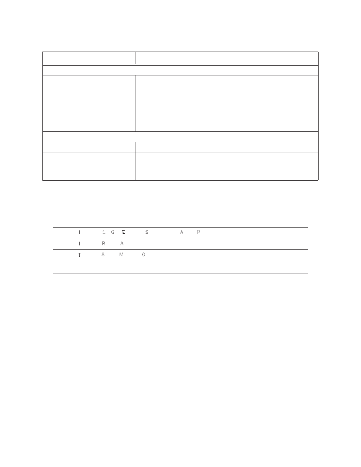
Ordering Information
Table 1-5: IntelliVue Telemetry System 1.4 GHz Access Point Part Numbers
Device/Option Part Number/Option Number
ntelliVue ITS4843B 1.4 GHz Enhanced Smart-Hopping Access Point 989803171211
I
I
ntelliVue ITS4846A Remote Antenna 865052
ntelliVue Telemetry System Mounting Options
I
• Above & Below Ceiling Tile-mount Option for 989803171211 or
865052
453564052201 or
862415/K05
IntelliVue Telemetry System 1.4 GHz Core Access Point/Remote Antenna Installation Guide 1-
11

Chapter 1: Overview
DRAFT-3
1-12
 Loading...