

Philips VL1000 TS, VL1000 TSD, VL1000 AS, VL1000 AI, VL1000 TI Service Manual
...

VARI❋LITE® - VL1000™ ERS LUMINAIRE SERVICE MANUAL
VARI❋LITE® is a trademark owned by Genlyte Thomas Group LLC and is registered in the United States and other countries.
VL500™, VL1000™, VL2000™, VL2201™, VL2202™, VL2400™ (and the individual product designations) , VL3000™,
VL3500™, Series 500
VARI❋BRITE
VARI❋LITE® products are protected by one or more of the following patents, and other pending patent applications worldwide:
U. S. Patents No. 6,123,436; 6,113,25 2; 6,046,861; 6,031,74 9; 6,01 1,640; 5,96 9,868; 5,959,768; 5, 934,794; 5,882, 107; 5,829,868;
5,825,548; 5,798,619; 5,774,273; 5,769,527; 5,758,956; 5,728,994; 5,640,061; 5,590,954; 5,454,477; 5,432,691; 5,367,444;
5,329,431; 5,307,295; 5,282,121; 5,278,742; 5,209,560; 5,186,536; 5,073,847; 5,010,459; 4,980,806; 4,972,306; 4,800,474;
4,779,176; 4,701,833; 4,602,321;
U. S. Design Patents No. 439,356; 420,332; 417,300; 415,301; 413,99 5; 377,338; 366,712; 359,574; 350,408; 347,113;
Australia Patents No. 693,691; 683,695; 667,109; 649,264; 646 ,588; 586,095; 576,400; 546,433;
Australia Design Patents No. 128,796; 128,795;
Canada Patents No. 2,070,670; 2,050,375; 1,270 ,675; 1,259,058; 1,181,795;
Canada Design Patents No. 81,234; 81,233; 76,046;
European (UK) Patents No. 0 652 400; 0 586 049; 0 565 218; 0 547 732; 0 534 710; 0 495 305 ; 0 474 202 ; 0 379 97 0; 0 25 3 08 2;
0 253 081; 0 248 974; 0 192 882; 0 140 994; 0 060 068;
Germany Patents No. 694 25 943.8; 693 14 122.0; 692 08 615.3; 692 07 692.1; 691 31 478.0; 691 21 029.2; 690 33 385.4; 37 89
166.9; 37 68 727.1; 37 51 804.6; 37 50 201.8; 35 87 270.5; 32 79 888.1; 32 74 291.6;
Germany Design Patents No. M 98 01 745.4; M 96 04 5 15. 9; M 96 04 5 14.0; M 94 0 7 689. 8; M 94 0 2 95 1.2; M 499 03 5 83.6; M
498 11 203.9; G 93 12 884.3;
Spain Patents No. 2 090 191; 2 084 289; 2 020 960; 0 548 328;
Spain Utility Model Patent No. 2.031.748;
Spain Design Patents No. 0.137.502; 0.137.501; 0.133.573;
Greece Patent No. 910.400.544;
Hong Kong Patents No. 965/1990; 285/1987;
Japan Patents No. 2,843,696; 2,059,669; 2,055,324; 2,0 02,168; 1,966,525; 1,889,481; 1,792,721; 1,770,241; 1,723,825;
1,683,007; 1,533,011;
Japan Design Patents No. 985,985-1; 985,985; 947,552; 945,436-1; 945,436; 1,106,089; 1,077,598; 1,072,598; 1,060,414;
1,002,123;
Korea Patents No. 76,310; 42,639; 283,770; 181,180;
Korea Design Patents No. 209,896; 209,895;
Mexico Patent No. 180,148;
Singapore Patents No. 663/90; 134/87;
Taiwan Patents No. 78,726; 66,975; 65,380; 28,275;
United Kingdom Design Registrations No. 2082526; 2072562; 2056387; 2056386; 2042174; 2038212; 2033108; 2029499.
™
, series 1000™, Series 2000™, Series 3000™, DICHRO❋TUNE™, VARI ❋IMAGE™,
™
, and the Vari-Lite Asterisk are also trademarks owned by Genlyte Thomas Group LLC.
Neutrik®, PowerCon®, and EtherCon® are registered trademarks of Neutrik, Inc.
All other brand or product names which may be mentioned in this manual are trademarks or registered trademarks of their
respective companies or organizations.
VL1000™ ERS Luminaire Service Manual
The information furnished in this manual is for informational use only and is subject to change without notice. Please check
www.vari-lite.com for latest version. Vari-Lite assumes no responsibility or liability for any errors or inaccuracies that may
appear in this manual. All information and graphics are property of Vari-Lite, 10911 Petal Street, Dallas, Texas 75238.
Version as of: 14-May-2009
Part number: 02.9663.0010 F
©2002-2009, Vari-Lite, a Philips group company. All Rights Reserved.
VL1000™ ERS Luminaire Service Manual
ii 14-May-2009 02.9663.0010 F

HOW TO OBTAIN WARRANTY SERVICE
How To Obtain Warranty Service
A copy of the Vari-Lite Limited Warranty was included in the shipping package for
this VARI❋LITE® product.
To obtain warranty service, please contact customer service at 1-877-VARI-LITE
(1-877-827-4548) or customerservice@genlytecontrols.com and request a Return
Material Authorization (RMA) for warranty service. You will need to provide the
model and serial number of the item being returned, a description of the problem or
failure and the name of the registered user or organization. If available, you should
have your sales invoice to establish the date of sale as the beginning of the warranty
period.
Once you obtain the RMA, pack the unit in a secure shipping container or in its
original packing box. Fill out the RMA form included at the end of this manual and
place in shipping container along with a copy of your invoice (if available). W r ite the
RMA number legibly on or near the shipping address label and return the unit, freight
prepaid to:
Vari-Lite
10911 Petal Street
Dallas, Texas 75238 USA
Attention: Warranty Service
As stated in the warranty, it is required that the shipment be insured and FOB our
service center.
Manual Revision History
PAGE NUMBER CHANGE NUMBER
Title Page – xviii F
1-205 F
VERSION DATE
Basic 14-March-02
Revision A 25-April-02
Revision B 02-May-02
Revision C 18-June-02
Revision D 23-October-02
Revision E 25-March-04
Revision F 14-May-2009
02.9663.0 010 F 14-May-2009 iii

VARI❋LITE® - VL1000™ ERS LUMINAIRE SERVICE MANUAL
Compliance Notice
FCC
This equipment has been tested and found to comply with the limits for a Class A
digital device pursuant to Part 15 of FCC Rules. These limits are designed to provide
reasonable protection against harmful interference when this equipment is operated in
a commercial environment. This equipment generates, uses, and can radiate radio
frequency energy and, if not installed and used in accordance with Vari-Lite system,
service, and safety guidelines, may cause harmful interference to radio communications. Operation of this equipment in a residential area is likely to cause harmful interference, in which case the user will be required to correct the interference at his/her
own expense.
Declaration of Conformity
We declare, under our sole responsibility, that this product complies with the relevant
clauses of the following standards and harmonized documents (as applicable):
Safety:
(by Council Directive 73/23/EEC)
EN60598-1: 1997/A1:1998
EN60598-2-17: 1989/A2:1991
EN60922
Electromagnetic Compatibility:
(by Council Directive 89/336/EEC)
EN55022:1998, Class A
EN61000-4-2: 1995, Performance Criteria: B
EN61000-4-3: 1995, Performance Criteria: A
EN61000-4-4: 1995, Performance Criteria: B
EN61000-4-5: 1995, Performance Criteria: B
EN61000-4-6: 1996, Performance Criteria: A
EN61000-4-8: 1996, Performance Criteria: A
EN61000-4-11: 1994, Performance Criteria: B and C
EN61000-3-2: 1995
EN61000-3-3: 1994
We certify that the product conforms to the protection requirements of council directives: 73/23/EEC (LVD) and 89/336/EEC (EMC)
iv 14-May-2009 02.9663.0010 F
SAFETY NOTICE
Safety Notice
It is extremely important to read ALL safety information and instructions provided in
this manual and any accompanying documentation before installing and operating the
products described herein. Heed all cautions and warnings during installation and use
of this product.
Safety symbols used throughout this manual are as follows:
CAUTION advising of potential damage to product.
WARNING advising of potential injury or death to persons.
GENERAL INFORMATION PERTAINING TO PROTECTION AGAINST ELECTRICAL SHOCK, FIRE, EXPOSURE TO EXCESSIVE UV RADIATION, AND
INJURY TO PERSONS CAN BE FOUND BELOW.
WARNING:
INSTRUCTIONS FOR CONTINUED PROTECTION AGAINST FIRE
1. VARI❋LITE® luminaires have been designed for use only with certain Philips and Osram
HID lamps. Note lamp type (MSR400, MSR575HR etc.) before replacing lamps.
Installing another type of lamp may be hazardous.
2. Luminaires may be mounted on any type of surface as long as mounting instructions are
followed. See instructions detailed in this manual.
3. Replace fuses with same type and rating only.
4. Note distance requirement from combustible materials or illuminated objects for
VARI ❋LITE® luminaires.
WARNING:
INSTRUCTIONS FOR CONTINUED PROTECTION AGAINST ELECTRICAL
SHOCK
1. VARI❋LITE® luminaires are designed for dry locations only. Exposure to rain or
moisture may damage luminaire.
2. Disconnect power before servicing any VARI❋LITE® equipment.
3. Servicing to be performed by qualified personnel only.
WARNING: It is not recommended to power any VARI❋LITE® luminaire from a
dimmer - even in 'NONDIM' mode. Dimmer and non-dim modules are not suitable
sources of power because their output modifies the AC wave form. This may work for
a short time, but will eventually result in power problems, luminaire mis-operation
and/or failure. See Vari-Lite Technical Notice TN-229A for more information.
02.9663.0 010 F 14-May-2009 v

VARI❋LITE® - VL1000™ ERS LUMINAIRE SERVICE MANUAL
WARNING:
INSTRUCTIONS FOR CONTINUED PROTECTION AGAINST EXCESSIVE
EXPOSURE TO UV RADIATION
1. Many VARI❋LITE® luminaires use an HID type lamp that produces UV radiation. DO
NOT look directly at lamp.
2. It is hazardous to operate luminaires without lens or shield. Shields, lenses, or ultraviolet
screens shall be changed if they have become visibly damaged to such an extent that their
effectiveness is impaired. For example, by cracks or deep scratches.
WARNING:
INSTRUCTIONS FOR PROTECTION AGAINST INJURY TO PERSONS
1. Exterior surfaces of the luminaire will be hot during operation. Use appropriate safety
equipment (gloves, eye protection, etc.) when handling and adjusting hot equipment and
components.
2. Luminaires will have a hot lamp when operating. Disconnect power and allow lamp to
cool before replacing.
3. Arc lamps emit ultraviolet radiation which can cause serious skin burn and eye
inflammation. Additionally, arc lamps operate under high pressure at very high
temperatures. Should the lamp break, there can exist a danger of personal injury and/or
fire from broken lamp particles being discharged.
4. Wear eye protection when relamping.
5. Appropriate safety equipment (gloves, eye protection) should be used when handling
damaged lamps.
6. If lamp is touched with bare hands, clean lamp with denatured alcohol and wipe with
lint-free cloth before installing or powering up the luminaire.
7. The lamp shall be changed if it has become damaged or thermally deformed.
WARNING:
RF INTERFERENCE
1. This is a Class A product. In a domestic environment this product may cause radio
interference, in which case, the user may be required to take adequate measures.
ARC LAMP CHARACTERISTIC CONSIDERATIONS
1. Arc lamps require a period of time to relight after a power i nterruption or a severe voltage
dip. In some cases, lamp will automatically relight after it has cooled depending on Lamp
Power-Up State (L ON/ LOFF) system configuration setting.
2. Burning position is Universal.
vi 14-May-2009 02.966 3.0010 F

SICHERHEITSHINWEISE
Sicherheitshinweise
Es ist äußerst wichtig, ALLE Sicherheitsinformationen und -hinweise in diesem
Handbuch und dem beiliegenden Informationsmaterial zu lesen, bevor Sie die hierin
beschriebenen Produkte installieren bzw . be dienen. Halten Sie bei der Installation und
dem Einsatz dieses Produkts alle Warnhinweise und Vorsichtsmaßnahmen ein.
Folgende Sicherheitssymbole werden in diesem Handbuch verwendet:
VORSICHT - weist auf möglichen Produktschaden hin.
WARNUNG - weist auf mögliche Körperverletzung und Leb-
ensbedrohung hin.
NACHSTEHEND FINDEN SIE ALLGEMEINE HINWEISE ÜBER SICHERHEITSVORKEHRUNGEN GEGEN ELEKTROSCHOCK, FEUER, ÜBERHÖHTE
UV-STRAHLUNG UND KÖRPERVERLETZUNGEN.
WARNUNG:
HINWEISE ZUM FEUERSCHUTZ
1. VARI❋LITE®-Scheinwerfer sind ausschließlich für den Einsatz mit bestimmten Philips
und Osram HID-Lampen geeignet. Achten Sie auf den Lampentyp (MSR400,
MSR575HR etc.), bevor Sie die jeweiligen Lampen ersetzen. Die Installation eines
anderen Lampentyps kann gefährlich sein.
2. Scheinwerfer können auf jeder beliebigen Oberfläche montiert werden, solange Sie die
Montageanweisungen befolgen. Detaillierte Hinweise finden Sie in diesem Handbuch.
3. Ersetzen Sie Sicherungen nur mit Sicherungen vom gleichen Typ und gleicher Stärke.
4. Beachten Sie die Einhaltung des erforderlichen Sicherheitsabstandes der
VARI ❋LITE®-Scheinwerfer von brennbarem Material oder beleuchteten Objekten.
WARNUNG:
HINWEISE ZUM SCHUTZ GEGEN ELEKTROSCHOCK
1. VARI❋LITE®-Scheinwerfer eignen sich ausschließlich für trockene Standorte. Regen
oder Feuchtigkeit können die Scheinwerfer beschädigen.
2. Unterbrechen Sie die Stromzufuhr, bevor Sie mit der Arbeit an VARI❋LITE®-Geräten
beginnen.
3. Die Geräte sollten nur von qualifiziertem Personal gewartet werden.
WARNUNG:
HINWEISE ZUM SCHUTZ GEGEN ÜBERHÖHTE UV-STRAHLUNG
1. Viele VARI❋LITE®-Scheinwerfer verwenden einen HID-Lampentyp, der UV-Strahlen
abgibt. SCHAUEN SIE NICHT direkt in die Lampe.
02.9663.0 010 F 14-May-2009 vii

VARI❋LITE® - VL1000™ ERS LUMINAIRE SERVICE MANUAL
2. Es ist gefährlich, Leuchten ohne Linsen oder Blenden zu bedienen. Blenden, Linsen ode r
Ultraviolettschirme müssen ausgetauscht werden, sofern deren Schutzwirkung durch
sichtbare Beschädigung (z. B. Sprünge oder Schrammen) eingeschränkt ist.
WARNUNG:
HINWEISE ZUM SCHUTZ GEGEN KÖRPERVERLETZUNGEN
1. Bei Betrieb sind die Außenflächen der Scheinwerfer heiß. Verwenden Sie bei der
Bedienung von aufgeheizter Apparatur die jeweils geeignete Sicherheitsausrüstung
(Handschuhe, Augenschutz etc.).
2. Bei Betrieb der Scheinwerfer ist die Lampe heiß. Unterbrechen Sie die Stromzufuhr und
lassen Sie die Lampe abkühlen, wenn Sie diese austauschen.
3. Bogenlampen senden ultraviolette Strahlen aus, die Hautverbrennungen und
Augenentzündungen verursachen können. Der Betrieb von Bogenlampen erfolgt unter
Hochdruck und bei hohen T emperaturen. Sollte die Lampe zerbrechen, besteht die Gefahr
von Körperverletzung bzw. von Feuer, das von Lampenteilen ausgelöst werden kann.
4. Tragen Sie beim Austausch der Lampen einen Augenschutz.
5. Die geeignete Sicherheitsausrüstung (Handschuhe, Augenschutz) sollte beim Umgang mit
beschädigten Lampen verwendet werden.
6. Wenn die Lampe mit bloßen Händen berührt wird, reinigen Sie sie mit denaturiertem
Alkohol und einem flusenfreien Tuch, bevor Sie die Scheinwerfer installieren oder in
Betrieb nehmen.
7. Wenn die Lampe beschädigt oder durch Hitzeeinwirkung deformiert ist, muß diese
ausgetauscht werden.
WARNUNG:
HF-INTERFERENZ
1. Es handelt sich um ein Produkt der Klasse A. In einer Wohnumgebung kann das Produkt
Hochfrequenzstörungen verursachen. In diesem Fall müssen eventuell geeignete
Maßnahmen getroffen werden.
BESONDERHEITEN VON BOGENLAMPEN
1. Bogenlampen benötigen eine gewisse Zeitdauer, um nach einem Stromausfall oder einem
Spannungsgefälle wieder aufzuleuchten. In einigen Fällen wird die Lampe nach
Abkühlung automatisch wieder aufleuchten, je nach der Systemkonfigurationseinstellung
des Lampeneinschaltungsstatus (L ON/ LOFF).
2. Die Brennposition ist Universal.
viii 14-May-2009 02.9663.0010 F
NOTES DE SÉCURITÉ
Notes de sécurité
Avant de procéder à l’installation des produits décrits dans ce guide et de les mettre en
marche, il est extrêmement important de lire TOUS les renseignements et TOUTES
les directives de sécurité contenues dans ce guide ainsi que toute documentation jointe.
Tenir compte de tous les avertissements et suivre toutes les précautions pendant
l’installation et l’utilisation de cet appareil.
Les symboles de sécurité utilisés dans ce guide sont les suivants :
ATTENTION Ce symbole annonce que l’appareil risque
d’être endommagé.
AVERTISSEMENT Ce symbole annonce qu’il y a risque
d’accident grave ou même fatal.
CETTE SECTION CONTIENT DES INFORMATIONS GÉNÉRALES POUR SE
PROTÉGER CONTRE LES DÉCHARGES ÉLECTRIQUES , LES INCENDIES,
L’EXPOSITION EXCESSIVE AUX RAYONS UV ET TOUT AUTRE ACCIDENT
POUVANT ENTRAÎNER DES BLESSURES.
AVERTISSEMENT:
DIRECTIVES POUR SE PROTÉGER CONTRE LES INCENDIES
1. Les luminaires VARI❋LITE® ont été conçus pour être utilisés uniquement avec certaines
lampes Philips et Osram HID. Vérifier le type de lampe (MSR400, MSR575HR etc.)
avant de remplacer les lampes. L’installation d’un autre type de lampe peut poser un
danger.
2. Les luminaires peuvent être fixés sur tout type de surface tant que les directives de
montage sont respectées. Voir les explications détaillées dans ce guide.
3. Ne remplacer les fusibles qu’avec ceux du même type, ayant les mêmes caractéristiques.
4. Vérifier la distance à respecter entre les matériaux combustibles ou les objets illuminés et
les luminaires VARI❋LITE®.
AVERTISSEMENT:
DIRECTIVES POUR SE PROTÉGER CONTRE LES DÉCHARGES ÉLECTRIQUES
1. Les luminaires VARI❋LITE® sont conçus pour une utilisation au sec uniquement. Une
exposition à la pluie et à l’humidité risque d’endommager le luminaire.
2. Débrancher l’appareil avant de procéder à la révision de tout matériel VARI❋LITE®.
3. Les révisions doivent être effectuées uniquement par des personnes qualifiées.
02.9663.0 010 F 14-May-2009 ix

VARI❋LITE® - VL1000™ ERS LUMINAIRE SERVICE MANUAL
AVERTISSEMENT:
DIRECTIVES POUR SE PROTÉGER CONTRE UNE EXPOSITION EXCESSIVE
AUX RAYONS UV
1. Plusieurs luminaires VARI❋LITE® utilisent une lampe de type HID qui produit des
rayons UV. NE PAS fixer son regard sur la lampe.
2. L’utilisation des luminaires sans lentille ou blindage pose des risques. Tous blindages,
lentilles ou écrans ultraviolet visiblement endommagés au point que leur efficacité en est
affectée doivent être remplacés, par exemple s’il y a des fissures ou de profondes rayures.
AVERTISSEMENT:
DIRECTIVES POUR SE PROTÉGER CONTRE LES ACCIDENTS POUVANT
ENTRAÎNER DES BLESSURES
1. Les surfaces externes du luminaire deviennent brûlantes quand l’appareil est en marche.
Pour manœuvrer ou ajuster des appareils brûlants et leurs composants, se protéger
suffisamment (gants, protection pour les yeux, etc.).
2. La lampe du luminaire est brûlante lorqu’il est en marche. Débrancher le courant et
attendre que la lampe ait refroidi avant de la remplacer.
3. Les lampes à arc émettent des rayons ultraviolets pouvant causer de graves brûlures sur la
peau et une inflammation des yeux. De plus, les lampes à arc fonctionnent sous haute
tension à de très hautes températures. Si la lampe se casse, les particules de la lampe
cassée peuvent causer blessures et/ou incendie en s’éparpillant.
4. Se protéger les yeux pour remplacer la lampe.
5. Utiliser des appareils de protection appropriés (gants, protection des yeux) pour manier
des lampes endommagées.
6. Si la lampe a été touchée avec des mains nues, la nettoyer avec de l’alcool dénaturé et
l’essuyer avec un chiffon non-pelucheux avant d’installer ou de brancher le luminaire.
7. Si la lampe a été endommagée ou a reçu une déformation thermique, elle doit être
remplacée.
AVERTISSEMENT:
INTERFÉRENCE RF
1. Cet appareil est de Classe A. Dans un environnement domestique, cet appareil peut causer
des interférences radio, et si c’est le cas, l’utilisateur peut avoir à prendre des mesures
adéquates.
CONSIDÉRATIONS DES CARACTÉRISTIQUES DE LAMPES À ARC
1. Après une interruption de courant ou une baisse importante de voltage, les lampes à arc
mettent du temps avant de se rallumer. Dans certains cas, la lampe se rallumera
automatiquemet après s’être refroidie. Cela dépend de la manière dont le système est réglé
pour le statut de mise en marche de la lampe (L ON/ LOFF).
2. La position Brûler est Universelle.
x 14-May-2009 02.9663.0 010 F
AVISO SOBRE SEGURIDAD
Aviso sobre Seguridad
Es muy importante leer TODA la información e instrucciones sobre seguridad que se
indica en este manual así como en los documentos adjuntos antes de instalar y operar
los productos descritos. Se debe prestar atención a todos los avisos y advertencias
durante la instalación y uso de este producto.
Los símbolos de seguridad usados en este manual son los siguientes:
CUIDADO, indica posibles daños al producto.
ADVERTENCIA, indica posibles lesiones o muerte a las
personas.
LA INFORMACIÓN GENERAL RELACIONADA A LA PROTECCIÓN CONTRAGOLPES DE CORRIENTE ELÉCTRICA, INCENDIO, EXPOSICIÓN
EXCESIVA A RADIACIÓN ULTRA VIOLETA Y LESIONES A LAS PERSONAS
SE PUEDE ENCONTRAR SEGUIDAMENTE:
ADVERTENCIA:
INSTRUCCIONES PARA PROTECCIÓN CONTINUA CONTRA INCENDIO
1. Las luminarias VARI❋LITE® han sido diseñadas para ser usadas solamente con algunas
lámparas HID Philips y Osram. Tome nota del tipo de lámpara (MSR400, MSR575HR
etc.) antes de reemplazarla. Instalación de otro tipo de lámpara puede ser peligroso.
2. Las luminarias se pueden instalar en cualquier tipo de superficie siempre que se sigan las
instrucciones de instalación. Vea las instrucciones detalladas en este manual.
3. Reemplaze los fusibles solamente con los del mismo tipo y especificación.
4. Tome nota de los requerimientos de distancia de materiales combustibles u objetos
iluminados para las luminarias VARI❋LITE®.
ADVERTENCIA:
INSTRUCCIONES PARA PROTECCIÓN CONTINUA CONTRA CHOQUE
ELÉCTRICO
1. Las luminarias VARI❋LITE® están diseñadas solamente para lugares secos. La
exposición a la lluvia o humedad pueden dañar la luminaria.
2. Desconecte la energía antes de dar servicio a cualquier equipo de VARI❋LITE®.
3. El servicio debe ser realizado solamente por personal calificado .
02.9663.0 010 F 14-May-2009 xi

VARI❋LITE® - VL1000™ ERS LUMINAIRE SERVICE MANUAL
ADVERTENCIA:
INSTRUCCIONES PARA PROTECCIÓN CONTINUA CONTRA LA EXPOSICIÓN
EXCESIVA DE RADIAC IÓN ULTRA VIOLETA
1. Muchas luminarias VARI❋LITE® usan un tipo de lámpara HID que produce radiación
UV. NO mire directamente a la lámpara.
2. Es peligroso operar luminarias sin lentes o protectores. Debe cambiar los protectores,
lentes o pantallas ultravioletas si se aprecia que han sido dañadas, y que su efectividad
pudiera estar deteriorada. Por ejemplo, si tuvieran rajaduras o raspaduras profundas.
ADVERTENCIA:
INSTRUCCIONES PARA PROTECCIÓN CONTRA LESIONES DE PERSONAS
1. Las superficies exteriores de las luminarias están calientes durante su operación. Use un
equipo de seguridad apropiado (guantes, protección para los ojos, etc.) cuando haga
ajustes en el equipo y componentes que están calientes.
2. Cuando las luminarias están en operación la lámpara estará muy caliente. Desconecte la
energía y deje que la lámpara se enfríe antes de reemplazarla.
3. Las lámparas de arco emiten radiaciones ultravioletas que pueden ocasionar serias
quemaduras a la piel e inflamación a los ojos. Además, las lámparas de arco operan a alta
presión y muy alta temperatura. Si la lámpara se rompe, puede existir el peligro de
lesiones al personal o un incendio ocasionado por las partículas de la lámpara rota que se
caen.
4. Use protección para los ojos cuando vuelve a colocar una lámpara nueva.
5. Use un equipo de seguridad apropiado (guantes, protección para los ojos, etc.) cuando
trabaje con lámparas dañadas.
6. Si toca la lámpara con las manos, limpie la lámpara con alcohol desnaturalizado y con tela
sin pelusas antes de instalar o volver a conectar la luminaria.
7. Cambie la lámpara si está dañada o deformada termicamente.
ADVERTENCIA:
INTERFERENCIA RF
1. Este es un producto de Clase A. En el ambiente de la casa este producto puede ocasionar
radiointerferencia, en cuyo caso, el usuario debe tomar las medidas adecuadas.
CONSIDERACIONES SOBRE LAS CARACTERÍSTICAS DE LA LÁMPARA DE
ARCO
1. Las lámparas de arco requieren un período de tiempo para volver a iluminarse después de
una interrupción de energía o de una severa caída de voltaje. En algunos casos, la lámpara
se volverá a iluminar en forma automática después que se ha enfriado dependiendo de la
configuración del sistema de energía de la lámpara (L ON / L OFF) (L encendida / L
apagada).
2. La posición de encendido es universal.
xii 14-May-2009 02.9663 .0010 F
SAFETY NOTICE (JAPANESE)
02.9663.0 010 F 14-May-2009 xiii
VARI❋LITE® - VL1000™ ERS LUMINAIRE SERVICE MANUAL
xiv 14-May-2009 02.9663.0 010 F

Table of Contents
Introduction
Disclosure .................................................................................................................... 1
About This Manual...................................................................................................... 1
Additional Documentation........................................................................................... 2
Customer Service......................................................................................................... 2
Chapter 1. Description
Features
Standard Features................................................................................................... .... .. 4
Model Specific Features .............................................................................................. 4
Component Descriptions
External Luminaire Components................................................................................. 6
Luminaire Internal Head Components......................................................................... 7
Luminaire Internal Yoke Components......................................................................... 8
Arc Ballast Unit ........................................................................................................... 9
Dimmer Model............................................................................................................. 9
Principles of Operation
VL1000 Incandescent Source Luminaire................................................................... 10
VL1000 Incandescent Block Diagram - Without On-Board IGBT Dimmer...... 10
VL1000 Incandescent Cable Routing - Without On-Board IGBT Dimmer ....... 11
VL1000 Incandescent Block Diagram - With On-Board IGBT Dimmer........... 12
VL1000 Incandescent Cable Routing - With On-Board IGBT Dimmer............. 13
VL1000 Arc Source Luminaire ................................................................................. 14
VL1000 Arc Block Diagram............................................................................... 14
VL1000 Arc Cable Routing ................................................................................ 15
TABLE OF CONTENTS
Chapter 2. Maintenance
Testing
Running Parameter Tests ........................................................................................... 18
Maintenance Procedures
Lamp Replacement (Incandescent Model) ................................................................ 20
Lamp Replacement (Arc Model)............................................................................... 22
Align Lamp For Maximum Beam Irradiance............................................................ 24
Frame or Top Hat Replacement................................................................................. 25
Front Cover Removal................................................................................................. 26
Rear Head Assembly Removal.................................................................................. 27
Rotating Gobo Replacement...................................................................................... 28
Gobo Index Timing Belt Alignment.......................................................................... 30
Gobo Wheel Bulkhead Replacement......................................................................... 32
Gobo Gear Planet Alignment..................................................................................... 34
02.9663.0 010 F 14-May-2009 xv

VARI❋LITE® - VL1000™ ERS LUMINAIRE SERVICE MANUAL
Shutter Assembly Replacement.................................................................................. 36
Shutter Blade or Rack Replacement........................................................................... 38
Edge/Zoom/Color Bulkhead Replacement................................................................. 40
Fan/Temp Switch Assembly Replacement................................................................. 41
Beam-Size Iris Assembly Replacement ..................................................................... 42
Ignitor PCB Replacement........................................................................................... 43
Power Supply Replacement........................................................................................ 44
Controller PCB Replacement..................................................................................... 46
Tilt Encoder PCB Replacement.................................................................................. 48
Tilt Motor Assembly Replacement............................................................................. 49
.............................................................................................................................. 50
Pan Motor Assembly Replacement............................................................................ 51
DMX Input PCB Replacement................................................................................... 53
Cleaning Optical Lenses and Filters........................................................................... 54
Chapter 3. Illustrated Parts Breakdown
Drawing Trees
VL1000 Incandescent Luminaires.............................................................................. 56
VL1000 Arc Luminaires............................................................................................. 58
Top Assembly
Included Items Kit...................................................................................................... 60
Included Items Kit (continued)................................................................................... 61
Label Locations.......................................................................................................... 62
VL1000 Luminaire .....................................................................................................64
Front Cover Assembly ....................................................................................... ..... ....67
Gel Frame Holder Assembly ......................................................................................68
COT (Center of Travel) Flag Assembly .....................................................................69
Head Assembly
Head Assembly ...........................................................................................................71
Front Head Assembly .................................................................................................72
Edge Control, Zoom, Dimmer & Color Assembly .....................................................74
Color Changer Assembly ...........................................................................................76
Cover Plate Assembly ................................................................................................79
Edge Barrel Assembly ................................................................................................80
Lens #6 Assembly ......................................................................................................82
Lens #7 Assembly ......................................................................................................83
Lens #8 Assembly ......................................................................................................84
Fan Assembly .............................................................................................................85
Pulley Side Rail Assembly .........................................................................................86
Sensor Side Rail Assembly ........................................................................................87
Incandescent Gobo Wheel Assembly ......................................................................... 88
Temperature Sensor Electrical Assembly ..................................................................91
Arc Gobo/Dimmer Bulkhead Assembly ....................................................................92
Gobo Wheel Assembly ...............................................................................................95
Shutter 6 Rollers Assembly ........................................................................................97
Beam-Size Iris Assembly .........................................................................................100
xvi 14-May-2009 02.9663.0 010 F

TABLE OF CONTENTS
Rear Head Assembly ................................................................................................ 102
Back Cap Assembly ................................................................................................. 104
Yoke Assembly
Yoke Legs Assembly ............................................................................................... 107
Tilt Motor Assembly ................................................................................................ 110
Crossmember Assembly ..........................................................................................112
Inner Crossmember Assembly ................................................................................. 114
Outer Crossmember Assembly ................................................................................ 115
Pan Motor Assembly ................................................................. ..... .......................... 116
Pan Tube Assembly ................................................................................................. 118
DMX Input PCB Assembly ..................................................................................... 120
Cables
Arc Power Input (Pigtail) Cable Assembly ............................................................. 121
Pan EOT Cable Assembly ....................................................................................... 123
Tilt COT Cable Assembly ....................................................................................... 124
AC Line Input Cable Assembly ............................................................................... 125
Incandescent LVS AC Input Cable Assembly ......................................................... 126
Arc LVS AC Input Cable Assembly ........................................................................127
LVS Chassis Ground Cable Assembly ....................................................................128
Head to Backcap Ground Cable Assembly .............................................................. 129
Yoke to Head Ground Cable Assembly ................................................................... 130
Pan/Tilt Control Cable Assembly ............................................................................ 131
Ballast Control Link Cable Assembly .....................................................................133
Data I/O Link Cable Assembly ................................................................................134
LVS DC Output Cable Assembly ............................................................................135
Incandescent Power Input Cable Assembly ............................................................. 136
Incandescent Lamp Power Cable Assembly ......................................................... ...137
Arc Power to Ignitor Cable Asembly ....................................................................... 138
Ignitor to Lamp Socket Cable Assembly .................................................................139
Shutter Harness Cable Assembly ............................................................................. 140
Color/Gobo/Lens Harness Cable Assembly ............................................................ 142
Dimmer to LVS Cable Assembly ............................................................................ 145
Dimmer to Controller Cable Assembly ................................................................... 146
Dimmer to Lamp Socket Cable Assembly ............................................................... 147
575W Ballast I/O Cable Assembly .......................................................................... 148
Appendix A. Technical Bulletins
VL1000™ ERS Luminaire Technical Bulletins ...................................................... 151
02.9663.0 010 F 14-May-2009 xvii

VARI❋LITE® - VL1000™ ERS LUMINAIRE SERVICE MANUAL
(This page intentionally blank.)
xviii 14-May-2009 02.9663.0 010 F
Introduction
Disclosure
This technical manual is confidential property of Vari-Lite All information contained
herein is the sole and exclusive property of Vari-Lite and may not be used, disclosed,
or reproduced in any manner without the prior written consent of Vari-Lite
WARNING: It is important to read ALL accompanying safety instructions to avoid
damage to the product and potential injury to yourself or others.
About This Manual
This manual provides descriptions, repair procedures, and illustrated parts breakdowns
for all configurations of the VL1000™ ERS Luminaire. The manual is intended for
use by Vari-Lite personnel and by Vari-Lite’s Authorized Dealers and Service
Centers.
INTRODUCTION :
This manual covers the following models:
Model Part Number Source Dimmer Shutter Iris
VL1000 TS 20.9663.0001.02 Incandescent - X
VL1000 TI 20.9663.0001.03 Incandescent - X
VL1000 AS 20.9663.0001.12 Arc - X
VL1000 AI 20.9663.0001.13 Arc - X
VL1000 TSD 20.9663.0001.22 Incandescent 115V X
VL1000 TID 20.9663.0001.23 Incandescent 115V X
VL1000 TSE 20.9663.0001.32 Incandescent 240V X
VL1000 TIE 20.9663.0001.33 Incandescent 240V X
Note: Performing maintenance procedures contained in this manual may void the
product warranty. Refer to the Vari-Lite Limited Warranty card included in the
shipping package for this VARI❋LITE® product.
WARNING: It is not recommended to power any VARI❋LITE® luminaire from a
dimmer - even in 'NONDIM' mode. Dimmer and non-dim modules are not suitable
sources of power because their output modifies the AC wave form. See Vari-Lite
Technical Notice TN-229A for more information.
02.9663.0 010 F 14-May-2009 1

VARI❋LITE® - VL1000™ ERS LUMINAIRE SERVICE MANUAL
Additional Documentation
A support webpage for Series 1000 luminaires is available at www.vari-lite.com
(follow the Support link).
A user’s manual is available for installation and operation of all versions of the
VL1000™ ERS Luminaire. This manual is only available in electronic (PDF) format.
■ VL1000™ ERS Luminaire User’s Manual (02.9663.0001).
T echnical bulletins concerning the latest changes to VARI❋LITE® equipment are also
available at the website Technical Support Center. These are documentation
supplements that contain procedures for equipment upgrades, retrofits, and additional
repairs. Technical bulletins are integrated into the appropriate equipment manuals as
those manuals are revised.
Customer Service
Our Goal
At Vari-Lite, we are committed to providing you the highest quality in customer
service. Our comprehensive resources are available to help your business succeed and
ensure you get the full benefit of being a Vari-Lite customer. Whether your needs are
telephone troubleshooting assistance, product training or technical service, our fulltime staff of experienced professionals are on-hand to provide support.
How to Reach Us
For assistance in your area, call the dealer from which your product(s) were
purchased.
or
Contact an Authorized Service Center.
or
Contact the Vari-Lite Customer Service Department, 9am - 6pm CST Monday through
Friday, at the following:
phone: 1-877-VARI-LITE (1-877-827-4548)
fax: 1-214-647-8038
email: customerservice@genlytecontrols.com
Additional Resources
For additional resources and documentation, please visit our website at:
www.vari-lite.com and follow the Support link.
2 14-May-2009 02.9663.0 010 F

CHAPTER 1.
Description
This chapter provides an overview of luminaire features, components
and operations.
• Features
• Component Descriptions
• Principles of Operation
02.9663.0 010 F 14-May-2009 3
VARI❋LITE® - VL1000™ ERS LUMINAIRE SERVICE MANUAL
Features
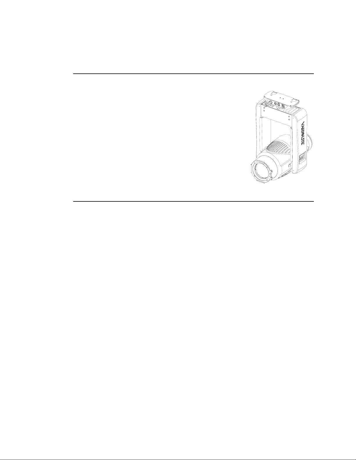
Standard Features
VL1000 Ellipsoidal Reflector Spotlight (ERS) luminaires
have the following standard features:
• Automated zoom optics system.
• Crossfading CYM color system.
• Diffusion system.
• Six-position rotating gobo wheel (five rotatable,
indexable gobo positions and one open gobo position).
• Repositional pan/tilt system.
• Control by DMX512 protocol.
Model Specific Features
Each individual configuration has the following specific features:
VL1000 TS (20.9663.0001.02)
• 1000W Tungsten Halogen lamp source.
• Four-blade shutter framing system.
VL1000 TI Luminaire (20.9663.0001.03)
• 1000W Tungsten Halogen lamp source.
• Beam-size iris mechanism.
VL1000 AS (20.9663.0001.12)
• 575W arc lamp source with external ballast unit.
• Four-blade shutter framing system.
VL1000 AI (20.9663.0001.13)
• 575W arc lamp source with external ballast unit.
• Beam-size iris mechanism.
4 14-May-2009 02.9663.0010 F

VL1000 TSD Luminaire (20.9663.0001.22)
• 1000W Tungsten Halogen lamp source.
• 115V on-board dimmer.
• Four-blade shutter framing system.
VL1000 TID Luminaire (20.9663.0001.23)
• 1000W Tungsten Halogen lamp source.
• 115V on-board dimmer.
• Beam-size iris mechanism.
VL1000 TSE Luminaire (20.9663.0001.32)
• 1000W Tungsten Halogen lamp source.
• 240V on-board dimmer.
• Four-blade shutter framing system.
DESCRIPTION :
1
VL1000 TIE Luminaire (20.9663.0001.33)
• 1000W Tungsten Halogen lamp source.
• 240V on-board dimmer.
• Beam-size iris mechanism.
02.9663.0 010 F 14-May-2009 5
VARI❋LITE® - VL1000™ ERS LUMINAIRE SERVICE MANUAL
Component Descriptions
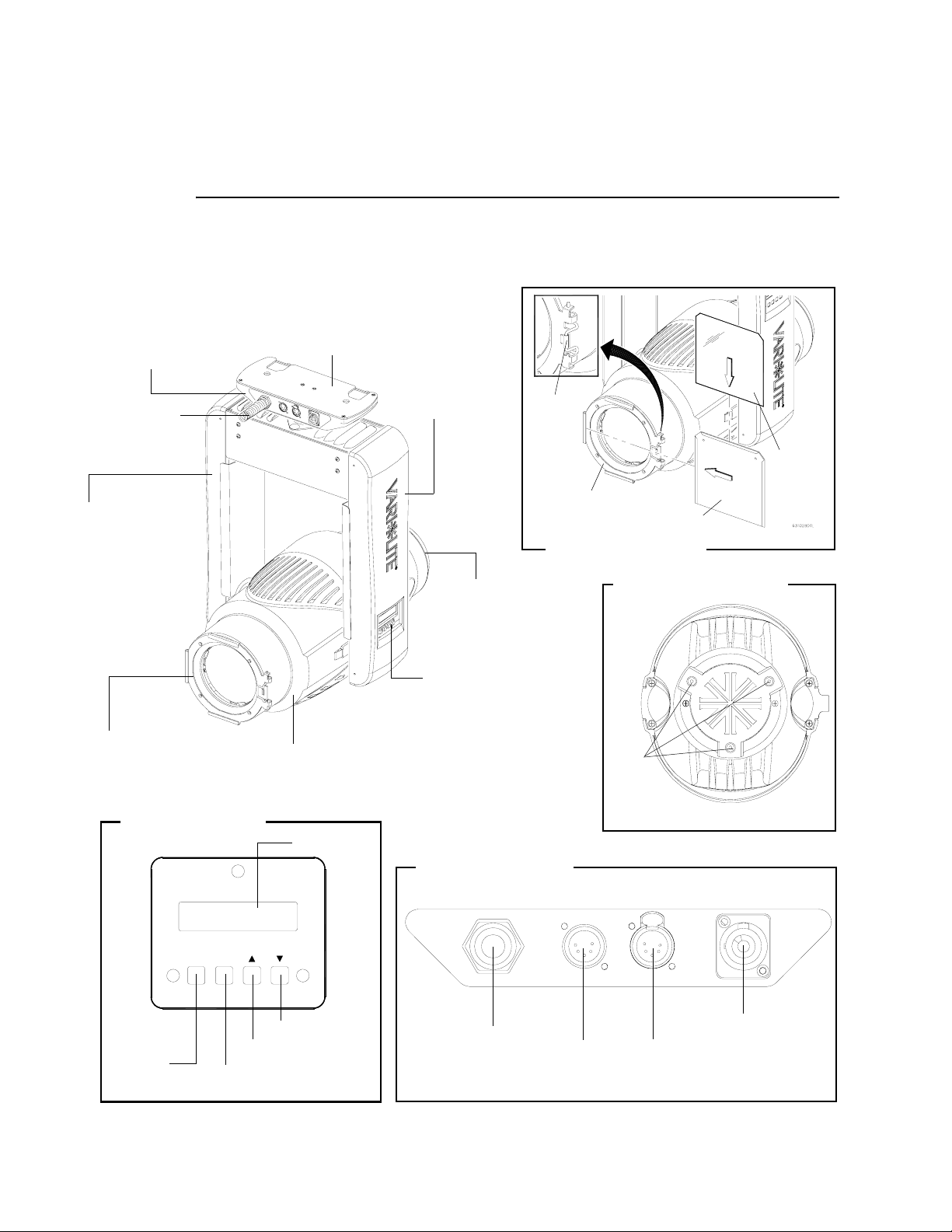
External Luminaire Components
The following illustration shows the external luminaire components and controls.
Input Panel
Provides DMX In and
Thru, and AC Power
connections.
Lamp Power
Input Cable
Yoke Leg (Power)
Contains power supply,
and ignitor board (arc
units) or dimmer (dimmer
units).
Accessory Frame Holder
Provides frame for
optional silks, frosts, color.
correction or top hats.
See detail...
Menu Display Controls
Base
Provides hook mounting
holes and safety cable
connection.
Yoke Leg (Control)
Contains main control
PCB and display PCB.
Backcap Assembly
Provides access to lamp
for replacement and
provides controls for
beam adjustment.
Menu Display
Used to input manual
commands, program, test,
set defaults and access
internal status information.
Head Assembly
Houses color, gobo, dimmer, strobe,
and optional shutter or iris mechanisms.
LCD Display
Input Panel Connections
Latch
Accepts frames
or top hats
Accessory Frame Holder
Accessory Frame
Beam Adjustment Controls
Beam
Adjust
Screws *
* Do not remove or use to access lamp.
Gel, Silk
or Frost
Address
ENTERMENU
Press to
show menu,
or if at first
level, the
current
address.
Press to select current menu
option or current data value.
Down / Decrease
Up / Increase
Lamp Power
Input Cable
Data In Data Thru
6 14-May-2009 02.9663.0010 F
3-Pole Neutrik
Locking Connector
for AC Input
DESCRIPTION :
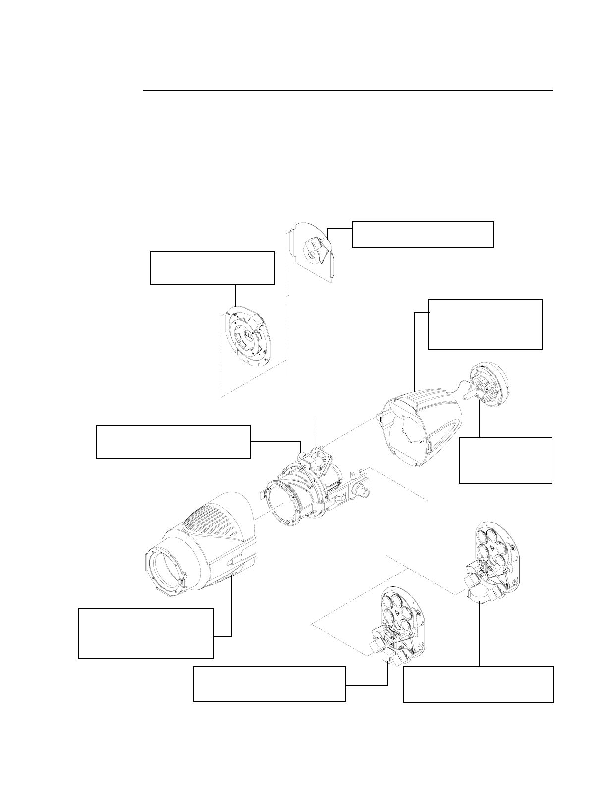
Luminaire Internal Head Components
The following illustration shows the major sub-assemblies that are located in the
luminaire head assembly.
A options - Shutter or Beam-size Iris bulkhead is dependent on model.
B options - Rotating Gobo Bulkhead version is dependent on model.
Beam-Size Iris Assembly (optional)
Provides beam sizing capabilities.
Shutter Assembly (optional)
Four-blade system can frame
and crop beam field and gobos.
Rear Head Assembly
Six-position rotating gobo
wheel with five rotatable,
indexable gobo positions
and one open gobo position.
1
Edge, Zoom, Dimmer Bulkhead
Contains automated zoom optics lenses,
crossfading CYM system, and diffusion.
Front Cover
Provides frame for mounting
silks, frosts, color correction
or top hat. Removed by unlatching
two latches.
Arc Gobo Bulkhead
Provides six position rotatable/indexable
gobo wheel for projecting images.
A
See options A
B
Backcap Assembly
Provides access to lamp
for replacement and
provides controls for
beam adjustment
See options B
Incandescent Gobo Bulkhead
Provides six position rotatable/indexable
gobo wheel for projecting images.
02.9663.0 010 F 14-May-2009 7
VARI❋LITE® - VL1000™ ERS LUMINAIRE SERVICE MANUAL
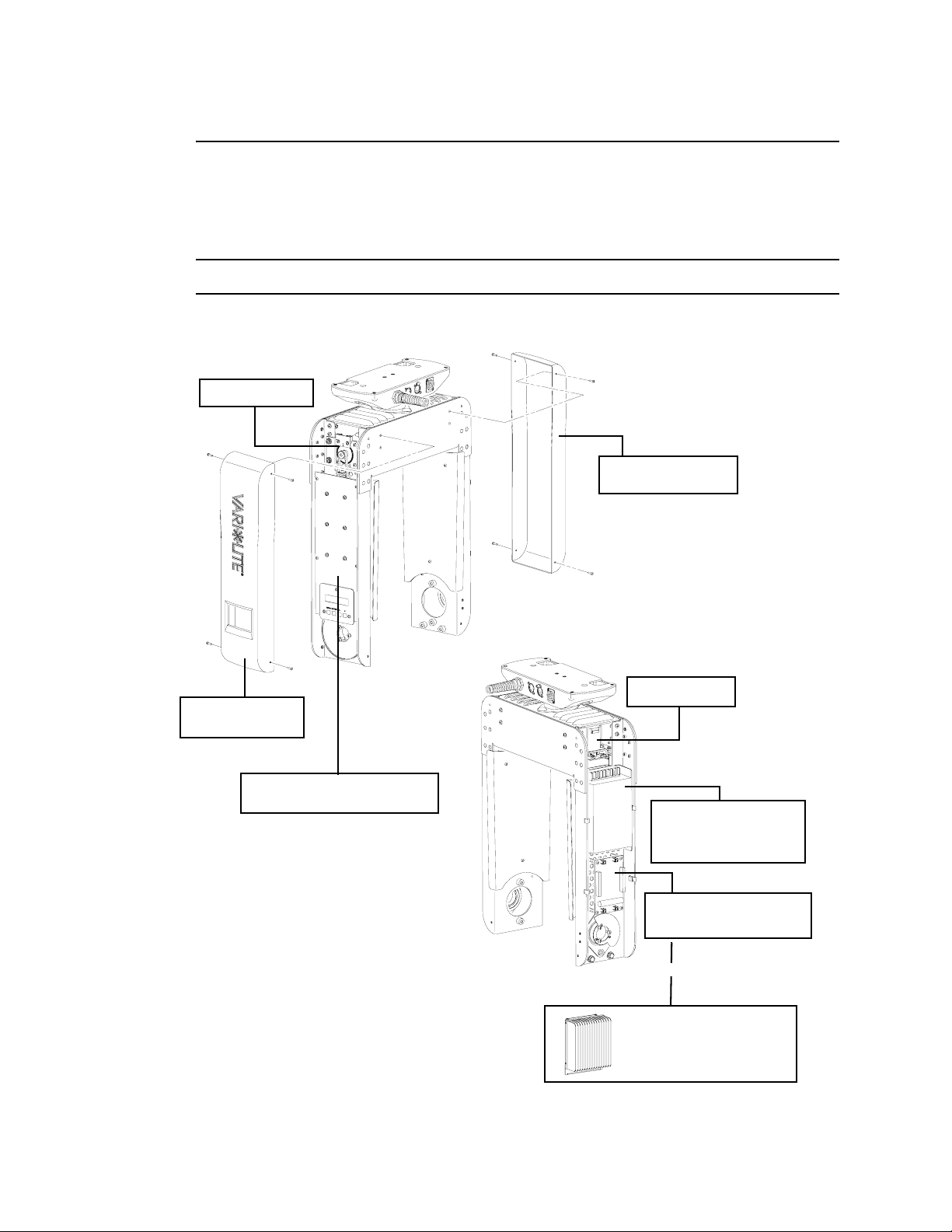
Luminaire Internal Yoke Components
The following illustration shows the major sub-assemblies that are located in the
luminaire yoke assembly.
Note: Head assembly not shown for clarity.
Tilt Mechanism
Yoke Arm Cover
(Power Supply Side)
Yoke Arm Cover
(Display Side)
Main Controller PCB
Luminaire control circuit board.
Pan Mechanism
150W Power Supply
Supplies power to
electronic and motor
components.
Ignitor PCB
Ignites lamp in arc models.
or
Internal Dimmer
Powers lamp in some models.
8 14-May-2009 02.9663.0010 F
DESCRIPTION :
1
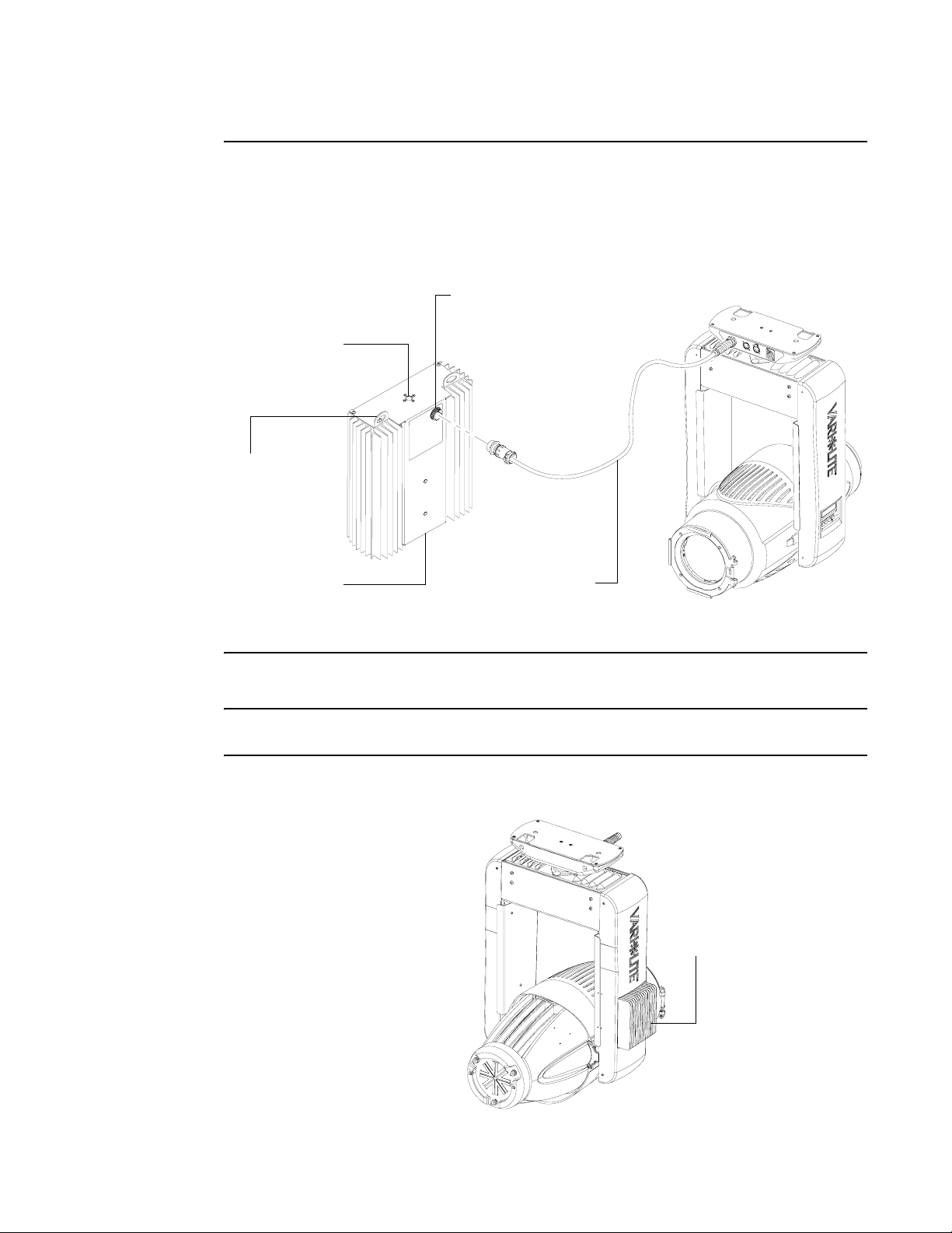
Arc Ballast Unit
An external ballast unit is included with VL1000 arc models. In this case, the lamp
power input cable is already connectorized for use with this unit.
The following illustration shows the external arc ballast components.
Lamp Connector
CPC-type connector for connecting
Lamp Power Input cable from luminaire.
Truss Hook Mount
Used to attach a truss hook.
Safety Cable Tab
Used to attach
safety cable clip.
Ballast Unit
Provides power for
arc lamp source.
Lamp Power Input Cable
Supplied cable and connector used
to connect luminaire to ballast unit.
40 inches (1m)
Note: The Lamp Power Input Cable has conductors for lamp power and ballast
control. It is not compatible with VARI❋LITE Series 300™ lamp runs.
Dimmer Model
An on-board IGBT dimmer is
included with VL1000
incandescent dimmer models.
The dimmer heatsink is visible
on the power-side yoke leg as
shown in this illustration.
On-Board IGBT Dimmer
Internal lamp power dimmer,
configured for either 120V or 240V
operation depending on model.
02.9663.0 010 F 14-May-2009 9
VARI❋LITE® - VL1000™ ERS LUMINAIRE SERVICE MANUAL
Principles of Operation
VL1000 Incandescent Source Luminaire
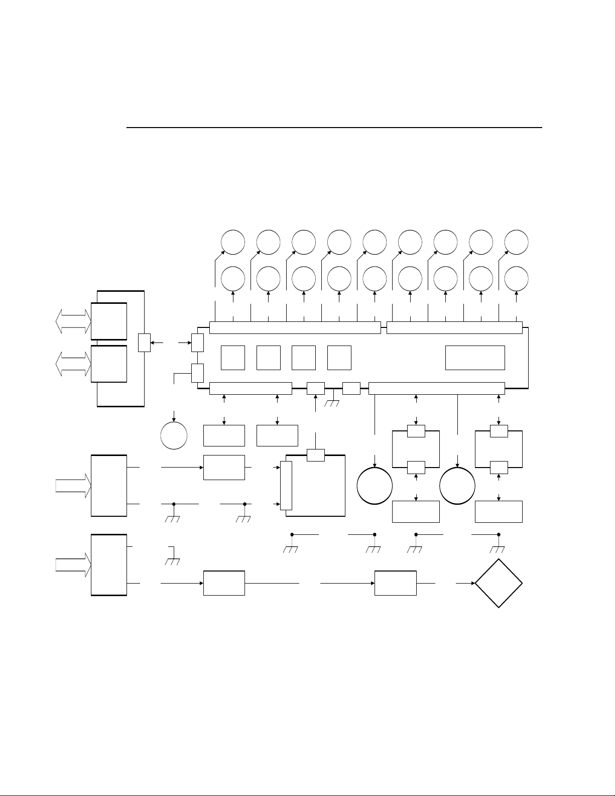
VL1000 Incandescent Block Diagram - Without On-Board IGBT Dimmer
DATA
I/O
DATA
I/O
AC LINE
POWER
LAMP
POWER
NEUTRIK
XLR-M
DMX INPUT
J2
NEUTRIK
XLR-F
DMX THRU
J1
DMX PCB
NEUTRIK
POWERCON
AC LINE IN
2015
USER
PROVIDED
CONNECTOR
FOR LAMP
PWR INPUT
FROM
DIMMER
2030
J3
2040
2042
AC LINE
16/2
2015
AC GND
16/1
2015
DIMMER GND
1.5/1
2030
LAMP
POWER
1.5/2
2030
PIGTAIL
DATA
22/5
2022
FAN
24/2
(SHUTTERS)
(WITHOUT)
FAN
1
2
J8
J1
AC GND
22x4
2016
CHASSIS
GND STUD
CHASSIS
GND STUD
1766
ZOOM
MOTOR
1202
EDGE
MOTOR
M1
24/4
M2
24/4
J4
SENSOR 1
26/4
GOBO WHEEL
SENSOR
TERM
BLOCK
TERM
BLOCK
1202
GOBO
INDEX
1202 1520
GOBO
WHEEL
1
M3
24/4
AC LINE
AC GND
M4
24/4
SENSOR 2
26/4
GOBO INDEX
SENSOR
22x4/2
2016
16/1
2017
YOKE
GND STUDS
M5
24/4
AC
IN
2
1520
BLUE
MOTOR
1520
AMBER
MOTOR
M7
24/4
M6
24/4
+24V
18/4
2024
+24V
LOW
VOLTAGE
SUPPLY
HEAD GND
LAMP
POWER
22x4/2
2031
1520 1766
MAG
MOTOR
DIFF
MOTOR
M8
24/4
DOWNUPMENU ENTER
J7J6J4
YOKE TO
22x4
2019
M9
24/4
DIMMER
ARC
( )
ONLY
1202/1326
B.S.IRIS/
SHUTTER
ROTATE
M12
24/4
M13
26/4
1301
SHUTTER
FRAME
1301
SHUTTER
FRAME
M14
26/4
J1
MAIN CONTROL
PCB ASSY
J5
SENSOR 3,4,5
M10
PAN ENCODER
24/4
2020
PAN
MOTOR
PCB ASSY
PAN EOT
PAN EOT
SENSOR
HEAD
GND STUDS
AMP
SERIES 30
1301
1A
1B
M15
26/4
2A
SHUTTER
FRAME
1301
2B
SHUTTER
FRAME
M16
26/4
1301
3A
SHUTTER
FRAME
1301
3B
SHUTTER
FRAME
M17
26/4
M18
26/4
20402050
DISPLAY8
20202050
M11
24/4
2020
2018
SENSOR 6,7,8
TILT ENCODER
24/5
J1 J1
J2 J2
TILT
26/4
MOTOR
18501850
HEAD TO
BACK CAP
LAMP
POWER
16/2HT
2032
BRAID
21
M19
26/4
24/5
PCB ASSY
TILT COT
26/4
TILT COT
SENSOR
1000W
INCAND
LAMP
1301
4A
SHUTTER
FRAME
1301
4B
SHUTTER
FRAME
M20
26/4
BACK CAP
GND STUD
10 14-May-2009 02.9663.0010 F
DESCRIPTION :
1
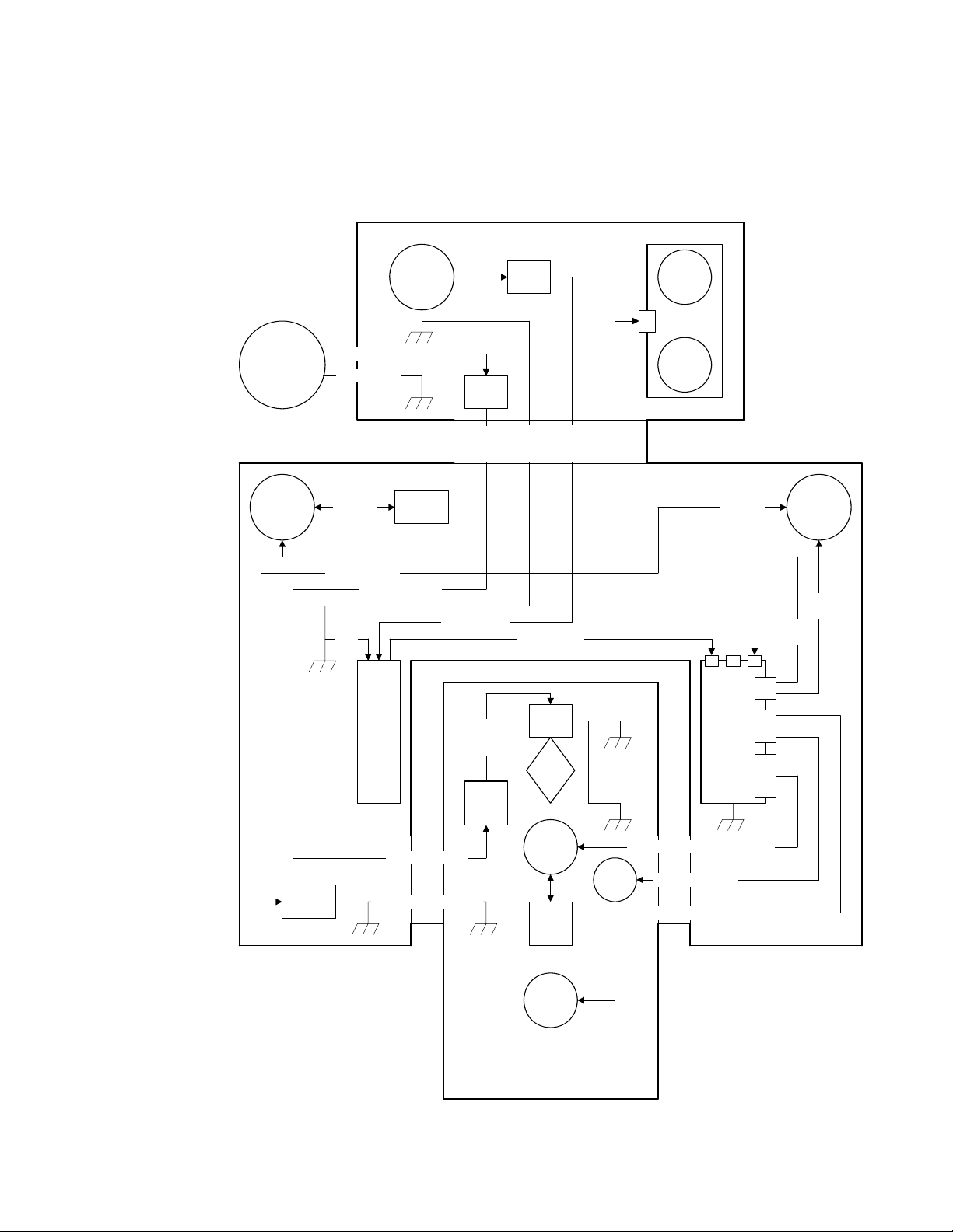
VL1000 Incandescent Cable Routing - Without On-Board IGBT Dimmer
CHASSIS
USER
PROVIDED
CONNECTOR
FOR LAMP PWR
INPUT FROM
DIMMER
PIGTAIL &
STRAIN RELIEF
GND
STUD
1
LAMP PWR
2030
DIMMER GND
NEUTRIK
POWERCON
AC LINE IN
2015
.
GND
STUD
2
AC
LINE
2015
TERM
BLOCK
LAMP
PWR
2031
TERM
BLOCK
AC
GND
2016
AC
LINE
2016
DMX
DATA
2022
DMX PCB
5
PAN
TUBE
XLR-M
DMX
INPUT
XLR-F
DMX
THRU
TILT
COT
2002
PAN
MOTOR
& ENC
PCB
LAMP
PWR
2031
TILT COT
SENSOR
PAN EOT
PAN - 2020
TILT COT - 2002
LVS
.
GND
2017
GND STUD
2001
PAN EOT
SENSOR
LAMP PWR - 2031
AC GND - 2016
LVS
ASSY
LAMP PWR - 2031
YOKE/HEAD GND - 2019
GND STUD GND STUD
TILT
TUBE
AC LINE - 2016
LAMP
PWR
2032
AMP
SERIES
30
+24VDC - 2024
LAMP
SOCKET
INC
LAMP
10
CONTROL
MOTORS
2
GOBO
SENSE
8
SHUTTER
MOTORS
(OPT)
BACK CAP
GND STUD
BACK CAP/
HEAD GND
2018
GND STUD
10 MOTORS/ 2 SENSORS - 2050
FAN
8 MOTORS - 2040
YOKE
TILT COT
PAN - 2020
DMX DATA - 2022
5 54
MCB
PCB
FAN - 2040 or 2042
TILT
TUBE
2002
TILT
MOTOR
& ENC
PCB
TILT
2020
PAN
2020
20
40
50
HEAD
02.9663.0 010 F 14-May-2009 11
VARI❋LITE® - VL1000™ ERS LUMINAIRE SERVICE MANUAL
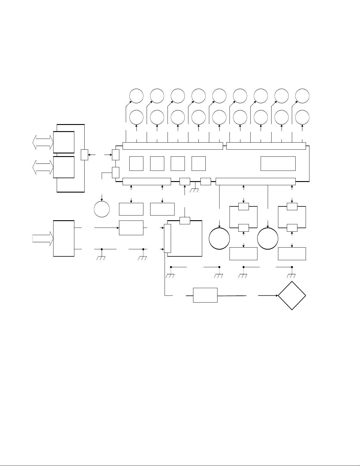
VL1000 Incandescent Block Diagram - With On-Board IGBT Dimmer
DATA
I/O
DATA
I/O
AC LINE
POWER
NEUTRIK
XLR-M
DMX INPUT
J2
NEUTRIK
XLR-F
DMX THRU
J1
DMX PCB
NEUTRIK
POWERCON
AC LINE IN
2015
J3
AC LINE
16/2
2015
AC GND
16/1
2015
2040
2042
DATA
22/5
2022
FAN
24/2
(SHUTTERS)
(WITHOUT)
FAN
1
J8
J1
AC GND
22x4
2016
CHASSIS
GND STUD
1766
ZOOM
MOTOR
1202
EDGE
MOTOR
M1
24/4
M2
24/4
J4
SENSOR 1
26/4
GOBO WHEEL
SENSOR
TERM
BLOCK
1202
GOBO
INDEX
1202 1520
GOBO
WHEEL
M3
24/4
AC LINE
AC GND
1
GND STUDS
M4
24/4
SENSOR 2
26/4
GOBO INDEX
SENSOR
22x4/2
2016
16/1
2017
YOKE
M5
24/4
AC
IN
2
1520
BLUE
MOTOR
1520
AMBER
MOTOR
M7
24/4
M6
24/4
+24V
18/4
2024
+24V
LOW
VOLTAGE
SUPPLY
HEAD GND
1520 1766
MAG
MOTOR
DIFF
MOTOR
M8
24/4
DOWNUPMENU ENTER
J7J6J4
YOKE TO
22x4
2019
M9
24/4
DIMMER
ARC
( )
ONLY
1202/1326
B.S.IRIS/
SHUTTER
ROTATE
M12
24/4
M13
26/4
1301
SHUTTER
FRAME
1301
SHUTTER
FRAME
M14
26/4
J1
MAIN CONTROL
PCB ASSY
J5
SENSOR 3,4,5
M10
PAN ENCODER
24/4
2020
PAN
MOTOR
PCB ASSY
HEAD
GND STUDS
PAN EOT
PAN EOT
SENSOR
1301
1A
1B
M15
26/4
2A
SHUTTER
FRAME
1301
2B
SHUTTER
FRAME
M16
26/4
1301
3A
SHUTTER
FRAME
1301
3B
SHUTTER
FRAME
M17
26/4
M18
26/4
20402050
DISPLAY8
20202050
M11
24/4
2020
2018
SENSOR 6,7,8
TILT ENCODER
24/5
J1 J1
J2 J2
TILT
26/4
MOTOR
18501850
HEAD TO
BACK CAP
21
BRAID
M19
26/4
24/5
PCB ASSY
TILT COT
26/4
TILT COT
SENSOR
1301
4A
SHUTTER
FRAME
1301
4B
SHUTTER
FRAME
M20
26/4
BACK CAP
GND STUD
LAMP
POWER
16/2HT
2032
DIMMER
115V or 240V
LAMP
POWER
22x4/2
2031
1000W
INCAND
LAMP
12 14-May-2009 02.9663.0010 F
 Loading...