

Page 1

Removable Backup System
Hardware Installation Guide
Installing the Velocity Series Removable Backup System .......... 2-3
Connecting the Velocity Series Removable Backup System ..... 4-5
Setting Up the Velocity Series Removable Backup System ...........
Changing Your Computer’s Setup Conguration ........................... 7-9
Removing the Velocity Series Removable Drive ..........................
CMS Support .................................................................................11
6
10
Page 2
Installing the Velocity Series Removable Backup System
Your new CMS Velocity Series Removable Backup System comes fully assembled. A 4-pin power connector and
Serial ATA cable are included for the connection of the Removable Serial ATA hard drive into your computer. The
following items are also included:
1 Velocity Series Removable Backup System 1 BounceBack Professional software CD-ROM
1 Getting Started Guide 4 Screws
Installing the Velocity Series Removable Backup System
1 Shut down your computer.
2 Remove/Unplug the computer’s power cable.
3 Carefully open your computer case to gain access to the inside.
Please refer to your computer’s Manual if you are not sure how
to properly open your case.
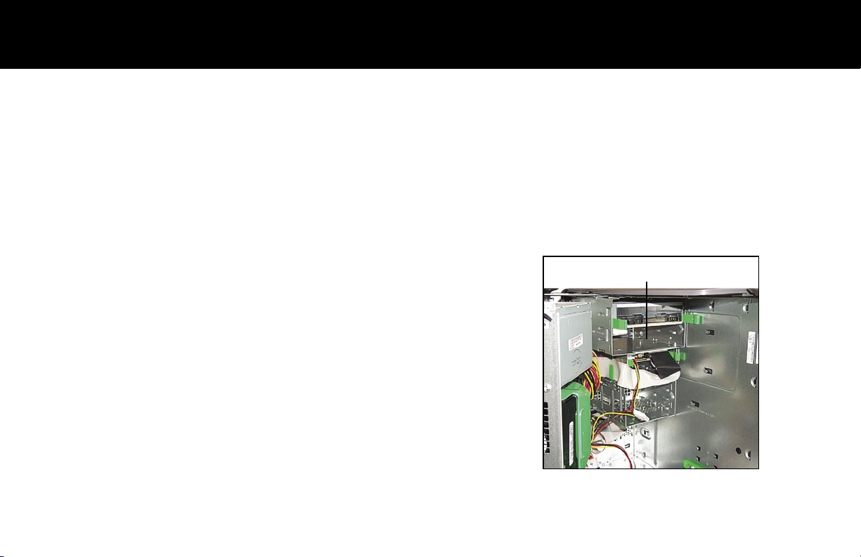
Note: Installation requires an unused/empty 5.25” drive bay slot (see
Figure 1).
4 Remove the selected 5.25” drive bay face plate.
Figure 1: Unused/empty drive bay
5 You will need to determine if the selected drive bay will require
screws or guide rails to mount the Removable bay.
2
Page 3
Installing the Velocity Series Continued...
Mounting the Removable Backup System with screws: If the selected drive bay will require screws to mount
the Removable Backup System, you will nd four screw holes, two on each side of the unused bay.
• Install the Removable Backup system into the unused bay through the front opening of the computer case
(where you removed the face plate).
• Slide the Removable Backup system all the way into the unused bay until the screw holes match up.
• Use the provided screws to secure the Removable bay into place.
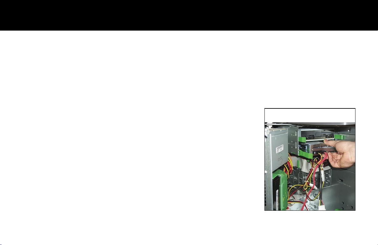
Mounting the Removable Backup System with guide rails: If the selected
drive bay will require guide rails to mount the Removable Backup System
into place, you can connect the rails directly onto the sides of the System.
(see your computer’s Manual for the location of your drive bay’s guide rails.)
• Install the guide rails onto the sides of the Removable Backup System
using the four screws provided with this product.
• Slide the Removable Backup system into the unused drive bay through
the back (or front depending on your system) of the bay until the rails
lock into place (see Figure 2).
Note: You may need to temporarily disconnect a few cables to gain access
to the selected drive bay. This will allow you to slide the Removable Backup
System into place through the back of the selected bay as shown in Figure 2.
Remember to reconnect the cables after you have installed the system.
Figure 2: Installing the Removable bay
into the unused bay.
3
Page 4

Connecting the Velocity Series Removable Backup System
Follow these steps to connect the Velocity Series Removable Backup
Figure 3: Available power connector
System’s Serial ATA hard drive to your computer:
1 Connect the Removable Backup System’s 4-pin power connector to
an available power connector in your case (see Figure 3).
2 Connect the Removable Backup System’s Serial ATA connector:
• If your mother board has available onboard Serial ATA connectors,
insert the Removable Backup System’s Serial ATA cable into an
available connector (see Figure 4).
Figure 4: Onboard Serial ATA
connectors
• If your mother board does not have an available onboard Serial
ATA connector, you will need to install a Serial ATA PCI Controller
Card rst. Follow the installation instructions of the guide that ships
with the Serial ATA PCI Controller Card. (Serial ATA PCI Controller
Cards can be purchased from CMS at (714) 424-5520 or online at
www.cmsproducts.com, part number: VELOCITY-CONT).
Once the Serial ATA PCI Controller Card is installed, you can
connect the Removable Backup System’s Serial ATA connector to
your Serial ATA PCI Controller Card.
3 Before you close your computer, please make sure you have completed all the necessary steps for
installing the Velocity Series Removable Backup System. Use the provided check list.
4
Page 5

Connecting the Velocity Series Continued...
Velocity Series Removable Backup System Installation Check List:
Shut down your computer and remove/unplug the power cable.
Carefully open your computer case.
Locate an unused 5.25” drive bay and remove it’s face plate.
Mount the Velocity Series Removable Backup System into the selected unused drive bay and secure it
into place using either the screws or guide rails as detailed in the instructions.
Connect the Removable Bay’s 4-pin power connector.
Connect the Removable Bay’s Serial ATA connector.
4 Close your computer case.
5
Page 6

Setting Up the Velocity Series Removable Backup System
1 Turn your computer back on.
2 Windows should recognize the new Velocity Series Serial ATA hard drive and install the correct driver for
you. To verify that the Velocity Series has been installed properly, follow these steps:
• Click Start and then My Computer. The Velocity Series Serial ATA hard drive should now be listed in
your device list. If so, you can now begin the installation of the BounceBack Professional Software (see
Installing the BounceBack Professional Software). If the Velocity Series Serial ATA hard drive does not
appear in your device list, your computer may not have “automatic conguration” enabled.
Review the information in the next section, “Changing Your Computer’s Setup.”
6
Page 7

Changing Your Computer’s Setup
If the Velocity Series is not recognized by your computer (in the “My Computer” folder) in the device list you will need
to enter your computer’s setup. The following steps will guide you through this process.
1 Restart your computer. Watch carefully for the startup key information. In most cases this will show up in
one of the corners of your screen as the computer restarts. The key information will only be present for a
short amount of time.
2 Quickly press the appropriate key,
Typically the F2 key depending on
your computers manufacturer(refer
to your computer’s Manual if you
need additional help with this step).
This will take you to your computer’s
setup screens.
Select
3
Select Drive Conguration and
press Enter.
The next screen will describe your
drive conguration and how to
proceed. Read the information on
types of possible congurations
which will help you choose your
path.
Figure 5
7
Page 8

Changing Your Computer’s Setup Continued...
Check to see what your current conguration is below (A, B or C). In this example our computer is congured like
Conguration A below, where Yes means enabled or in use and No means not in use or unknown device.
Conguration A Conguration B Conguration C
SATA Primary Drive Yes Yes No
SATA Secondary Drive No Yes No
Primary Master Drive Yes No Yes
Primary Slave Drive No No No
SATA PCI Controller Required No Yes Maybe
Depending on your conguration above, select the
appropriate device type and press the Enter key:
Conguration A — Select the Secondary SATA Drive.
Conguration B — You will need to install a SATA PCI
Controller because all your SATA ports are in use.
Conguration C — Select the SATA Primary
Drive. You should then enter the Boot Order
Setup to verify that your Primary Master Drive
is the boot Drive. Note: If you are unable to
change the Boot Order you will need to either
change your internal hard drive to a SATA drive
or install a PCI SATA Controller Card.
8
Select
Figure 6
Page 9

Changing Your Computer’s Setup Continued...
1 Select Drive Type and then press the
Enter key .
2 Use the + or – key to scroll through the
options. Make sure the Drive Type is set
to AUTO as in the example.
3 Use the Esc key to exit and save your
new settings.
Select
Figure 7
9
Page 10

Removing the Velocity Series Removable Drive
The Velocity Series Removable hard drive can be ejected from
the front of the computer.
1 Always turn off your computer before ejecting the drive.
2 Pull the handle on the Velocity Series outward and
carefully remove the drive (see gure 8).
Figure 8: Ejected Velocity Removable
Hard Drive
10
Page 11

CMS Support
What Do I Do If I Need More Help?
• Access CMS online support at: www.cmsproducts.com/support.
• Contact CMS Customer Service at (714) 424-5520 or e-mail cs@cmsproducts.com for warranty issues.
• Contact Technical Support (714) 424-5520 or e-mail support@cmsproducts.com for assistance with
the installation of your Velocity Series Backup System or help with a technical problem.
11
 Loading...