

Page 1
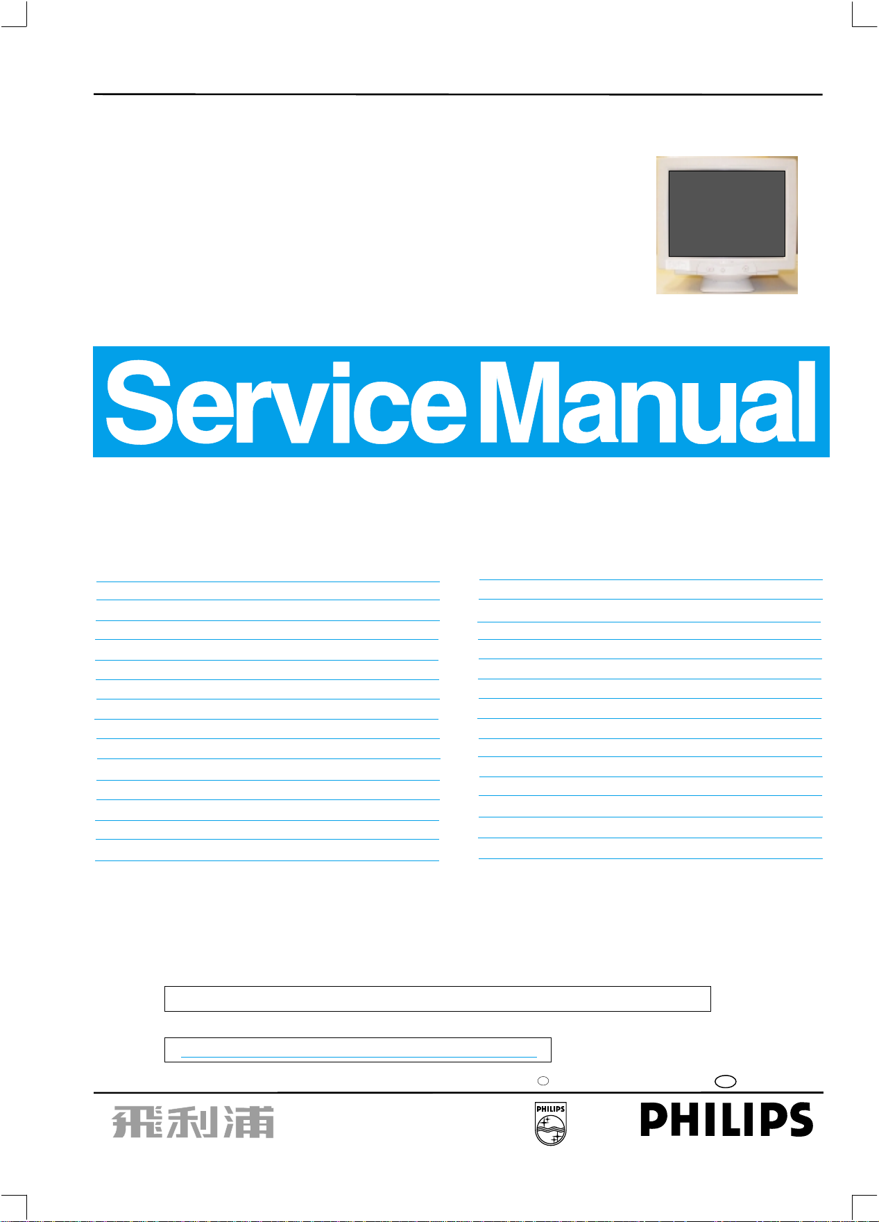
17" Auto scan Colour Monitor
http://jdwxzlw.5d6d.com/?fromuser=华盛维修
家电维修资料网,免费下载各种维修资料
Chassis :V20
Service
Service
Service
TABLE OF CONTENTS
Description Page
V20 107E5
DDC/Powersaving/MPR II/TCO
107E51/87
Horizontal frequencies
30-70kHz
Description Page
Important Safety Notice ------------------------------- 2
Technical Data ------------------------------------------ 3
Front control & OSD------------------------------------ 4
OSD menu tree------------------------------------------ 5
OSD Adjustments-----------------------------------6~12
Troubleshooting----------------------------------------12
Lock/Unlock, Factory mode, Burn in &
Service mode--------------------------------------------13
Warning and Notes ------------------------------------ 14
Mechanical Instructions ------------------------- 15~16
Wiring Diagram------------------------------------------17
Hex Data of DDC2B--------------------------------18 ~21
DDC Instructions -----------------------------------22~26
Electrical Adjustments --------------------------- 27~ 29
Safety test requirements (Hipot & Ground)------- 30
SAFETY NOTICE
ANY PERSON ATTEMPTING TO SERVICE THIS CHASSIS MUST FAMILIARIZE HIMSELF WITH THE CHASSIS
AND BE AWARE OF THE NECESSARY SAFETY PRECAUTIONS TO BE USED WHEN SERVICING ELECTRONIC
EQUIPMENT CONTAINING HIGH VOLTAGES.
Block Diagram ------------------------------------------31
Video Panel (A) Schematic Diagram ---------------32
Video Panel C.B.A.(A) --------------------------------33
Main Panel-Deflection (B) Schematic Diagram --34
Main Panel C.B.A.(B,C)-------------------------------35
Power Supply (C) Schematic Diagram-------------36
Key Control Panel (D) Schematic Diagram -------37
Key ControlPanel C.B.A. (D) ------------------------38
Repair Tips ----------------------------------------------39
Exploded View------------------------------------------40
Recommended
Spare parts list------------------------------------- 42~44
Repair flow chart----------------------------------- 45~52
General Product Specification-------------------53~81
General Troubleshooting Guide----------------82~104
parts list------------------------------41
CAUTION: USE A SEPARATE ISOLATION TRANSFORMER FOR THIS UNIT WHEN SERVICING.
REFER TO BACK COVER FOR IMPORTANT SAFETY GUIDELINES
Published by BCU Monitors Printed in Taiwan Copyright reserved Subject to modification Feb 15 2003
M
GB
3138 106 10261
Page 2
2
http://jdwxzlw.5d6d.com/?fromuser=华盛维修
家电维修资料网,免费下载各种维修资料
9
Proper service and repair is important to the safe, reliable
operation of all PHILIPS Company** Equipment.
The service procedures recommended by PHILIPS and
described in this service manual are effective methods
of performing service operations. Some of these service
operations require the use of tools specially designed for
the purpose. The special tools should be used when and
as recommended.
It is important to note that this manual contains various
CAUTIONS and NOTICES which should be carefully
Read in order to minimize the risk of personal injury to
service personnel. The possibility exists that improper
Service methods may damage the equipment. It also is
important to understand that these CAUTIONS and
NOTICES ARE NOT EXHAUSTIVE. PHILIPS could not
possibly know, evaluate and advise the service trade of
all conceivable ways in which service might be done or of
the possible hazardous consequences of each way.
Consequently, PHILIPS has not undertaken any such broad
evaluation. Accordingly, a servicer who uses a service
procedure or tool which is not recommended by PHILIPS
must first satisfy himself thoroughly that
neither his safety nor the safe operation of the equipment
will be jeopardized by the service method selected.
V20 107E5
Go to cover page
IMPORTANT SAFETY NOTICE
FOR PRODUCTS CONTAINING LASER :
DANGER-
CAUTION-
CAUTION-
TO ENSURE THE CONTINUED RELIABILITY OF THIS
PRODUCT, USE ONLY ORIGINAL MANUFACTURER'S
REPLACEMENT PARTS, WHICH ARE LISTED WITH THEIR
PART NUMBERS IN THE PARTS LIST SECTION OF THIS
SERVICE MANUAL.
Invisible laser radiation when open.
AVOID DIRECT EXPOSURE TO BEAM.
Use of controls or adjustments or
performance of procedures other than
those specified herein may result in
hazardous radiation exposure.
The use of optical instruments with this
product will increase eye hazard.
* * Hereafter throughout this manual, PHILIPS Company
Will be referred to as PHILIPS.
WARNING
Critical components having special safety characteristics
are identified with a by the Ref. No. in the parts list
and enclosed within a broken line* (where several critical
components are grouped in one area) along with the
safety symbol on the schematics or exploded views.
Use of substitute replacement parts which do not have
the same specified safety characteristics may create
shock, fire, or other hazards.
Under no circumstances should the original design be
modified or altered without written permission from
PHILIPS. PHILIPS assumes no liability, express or
implied, arising out of any unauthorized modification
Of design.
Servicer assumes all liability.
* Broken Line
Page 3
Technical Data
http://jdwxzlw.5d6d.com/?fromuser=华盛维修
家电维修资料网,免费下载各种维修资料
V20 107E5
Go to cover page
9
3
Technical Specification*
CRT
Size and deflection :17 inch/41cm,
Deflection angle : 90 degrees
Dot pitch : 0.27mm with black matrix
Face treatment : Anti-glare, anti-static,
Light transmission : 47%(PHL),46%(CPT),52%(LG),
Phosphor : P22
Recommended display area : 12.0" x 9.0" / 306 x 230 mm
Maximum display area
Scanning
Horizontal scanning : 30 - 70 KHz
scanning
Vertical : 50 - 160 Hz
Video
Video dot rate : 108 Mhz
Input impedance
-Video : 75 Ohms
- Sync : 4.7K Ohms
Signal input level : 0.7Vpp
Sync input signal : Separated sync. with TTL level
Sync polarities : Positive or negative
White Color Temperature
Chromaticity CIE coordinates:
Carton box
Size (with pedestal) : 419(W)x383(H)x397(D)
Net weight : 14 Kg
Power supply : 90 - 264 VAC, 50/60 Hz
Power consumption : 90 Watts Max.
Operating condition
Temperature : 0 C - 40 C
Relative Humidety : 10%-90%(W/O condensation)
Storage condition
Temperature : - 25 C - 65 C
Relative Humidity :5%-95%(W/O condensation)
o
at 9300 k x = 0.283 +/- 0.015 y = 0.297 +/- 0.015
o
at 6500 k x = 0.313 +/- 0.015 y = 0.329 +/- 0.015
at sRGB x = 0.313 +/- 0.015 y = 0.329 +/- 0.015
53.5%(ORION)
: 12.9" x 9.7" / 325 x 244 mm
Separate sync
OO
OO
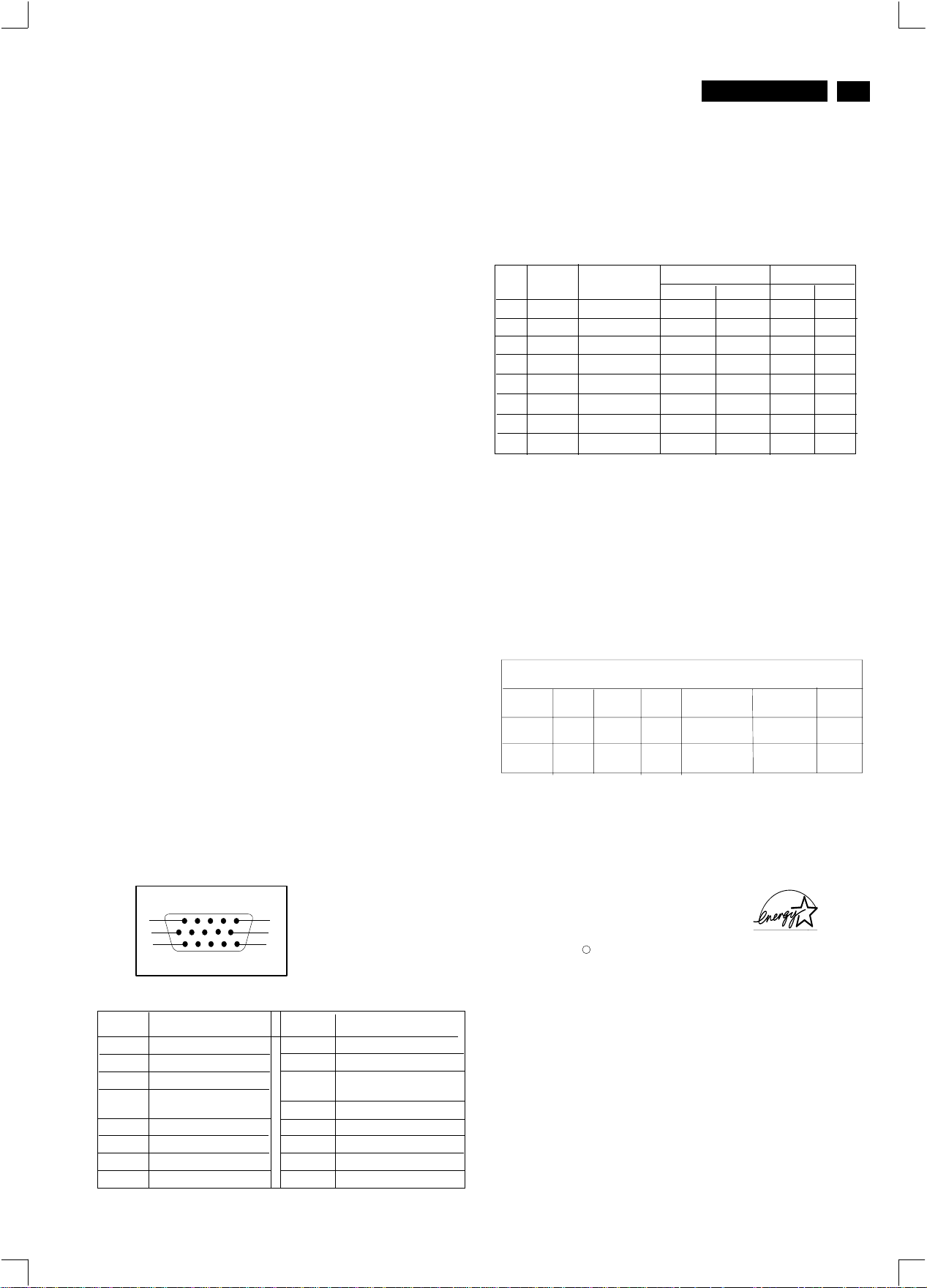
Pin assignment :
flat/square
Data Storage
Factory preset modes:
This monitor has 8 factory-preset modes as indicated in the
following table :
M01
M02
M03
M04
M05
M06
M07
M08
Mode
VGA
VGA
VGA
SVGA
SVGA
EVGA
EVGA
Resolution
720 x 400
640 x 480
640 x 480
800 x 600
800 x 600
1080 x 960
1024 x 768
1280 x 1024
Frequen
H(KHz)
31.5
31.47
43.3
46.9
53.674
60.0
68.7
64.0
V(Hz)
70
60
85
75
85
60
85
60
Sync polarity
H
V
+
-
-
-
-
-
+
+
+
+
+
+
+
+
+
+
Automatic Power Saving
If you have VESA's DPMS compliance display card or software installed
in your PC, the monitor can automatically reduce power consumption
when power saving function active. And if an input from keyboard,
mouse or other input devices is detected, the monitor will automatically
"wake up". The following table shows the power consumption and
signaling of this automatic power saving feature :
Power Management Definition
POWER
SAVING( % )
98 %
Yes
No
POWER
USED
Tyical 64 w
<1 w
VESA's
mode
ON
OFF
This monitor is ENERGY STAR compliant.
As an ENERGY STAR Partner, PHILIPS has determined that
this product meets the ENERGY STAR guidelines for energy
efficiency
Blanked
VIDEO
Active
H-SYNC
Yes
No
V-SYNC
0%
LED
COLOR
Green
Flashing
Green
1
6
11
Pin No.
Assignment
1
Red video input
Green video input
2
Blue video input
3
Identical output-
4
connected to pin 10
fground
5
Red video ground
6
Green video ground
7
Blue video ground
8
5
10
15
Pin No.
9
10
11
12
13
14
15
Assignment
+5V DDC supply
Logic. Ground
Identical outputconnected to pin 10
Serial data line(SDA)
H.Sync /H + V
V.Sync(VCLK for DDC)
Data clock line(SCL)
ENERGY STAR is a U.S. registered mark. AS AN ENERGY STAR
PARTNER, DELL Computer Corporation HAS DETERMINED THAT
THIS PRODUCT MEETS THE ENERGY STAR GUIDELINES FOR
:The 15-pin D-sub connector(male) of the signal cable
ENERGY EFFICIENCY.
R
Page 4
4
http://jdwxzlw.5d6d.com/?fromuser=华盛维修
家电维修资料网,免费下载各种维修资料
Go to cover page
9
V20 107E5
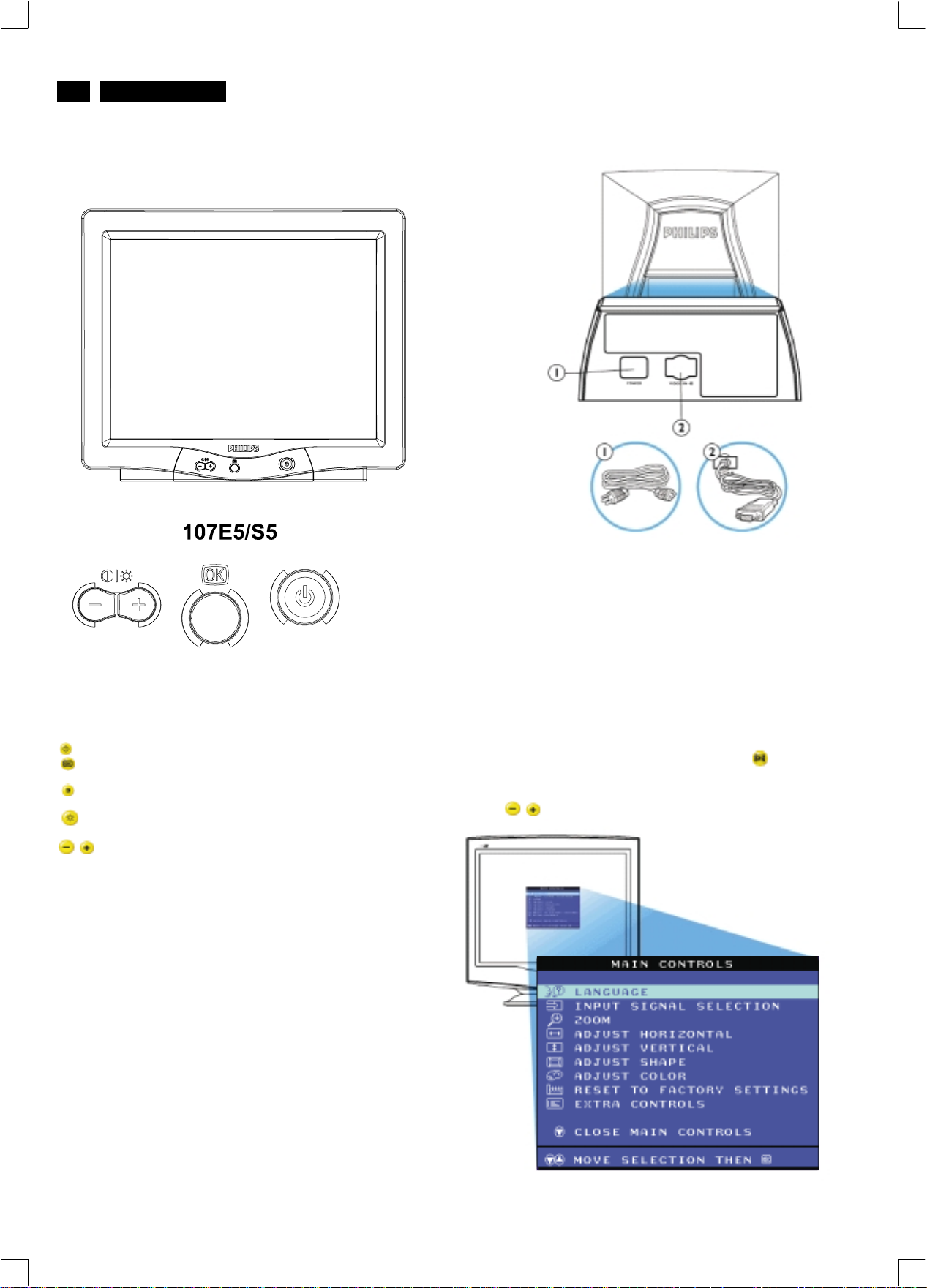
Front View
Front control & OSD
Rear view
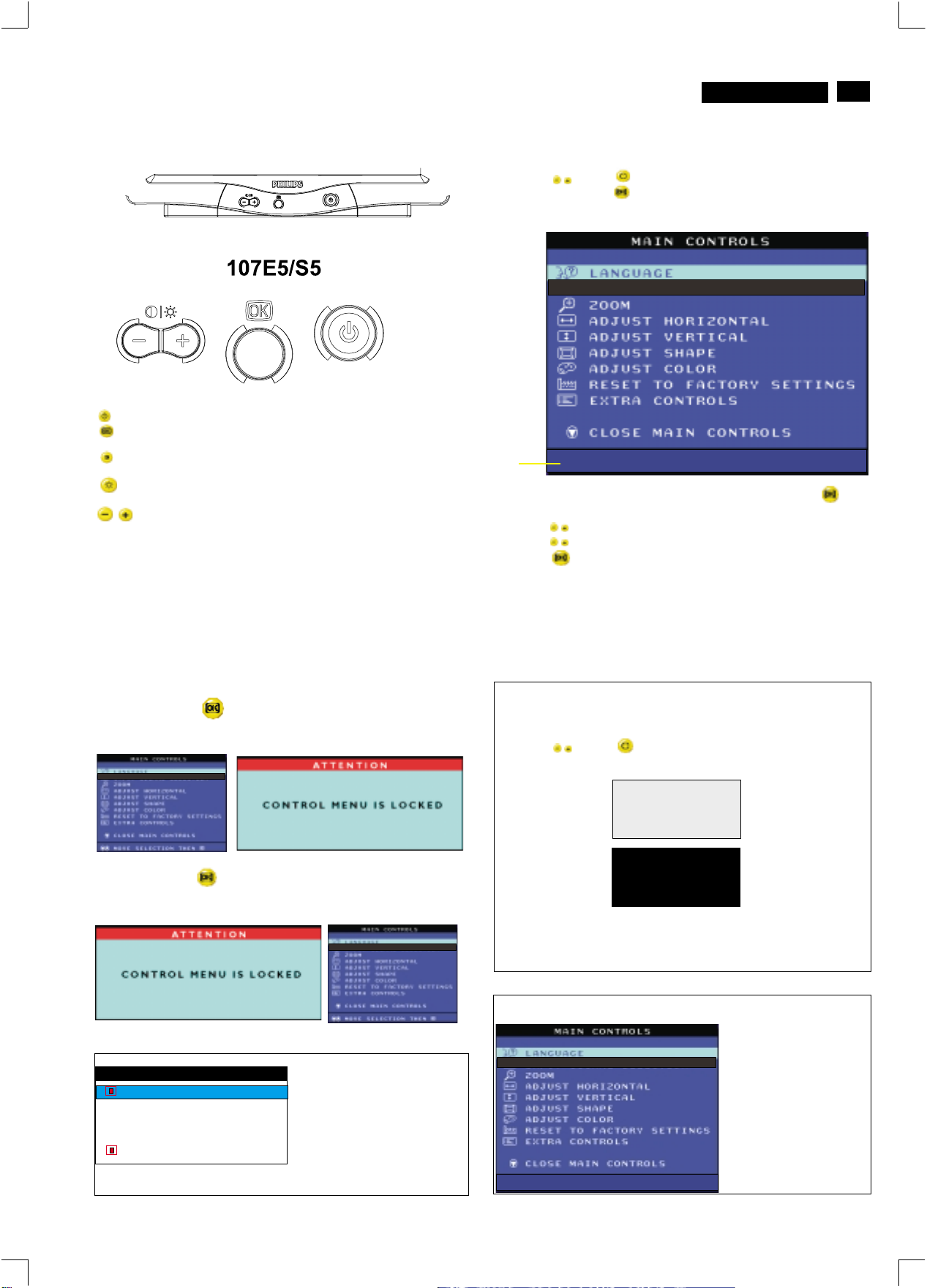
Power button switches your monitor on.
OK button which when pressed will take you to the OSD
controls
Contrast hotkey. When the "-" button is pressed,
the adjustment controls for the CONTRAST will show up.
Brightness hotkey. When the "+" button is pressed,
the adjustment controls for BRIGHTNESS will show up.
"-" and "+" buttons, are used for adjusting the OSD of your
monitor.
1. Power in - attach power cable here.
2. Video In - this is a cable which is already attached to your monitor.
Connect the other end of the cable to your PC.
Description of the On Screen Display
What is the On-Screen Display?
This is a feature in all Philips monitors which allows an end-user to
adjust screen performance of monitors directly though an on-screen
instruction window. The user interface provides user-friendliness and
ease-of-use when operating the monitor.
Basic and simple instruction on the control keys.
On the front controls of your monitor, once you press the button, the
On Screen Display (OSD) Main Controls window will pop up and you
can now start making adjustments to your monitor's various features.
Use the the keys to make your adjustments within.
Page 5
OSD menu tree
http://jdwxzlw.5d6d.com/?fromuser=华盛维修
家电维修资料网,免费下载各种维修资料
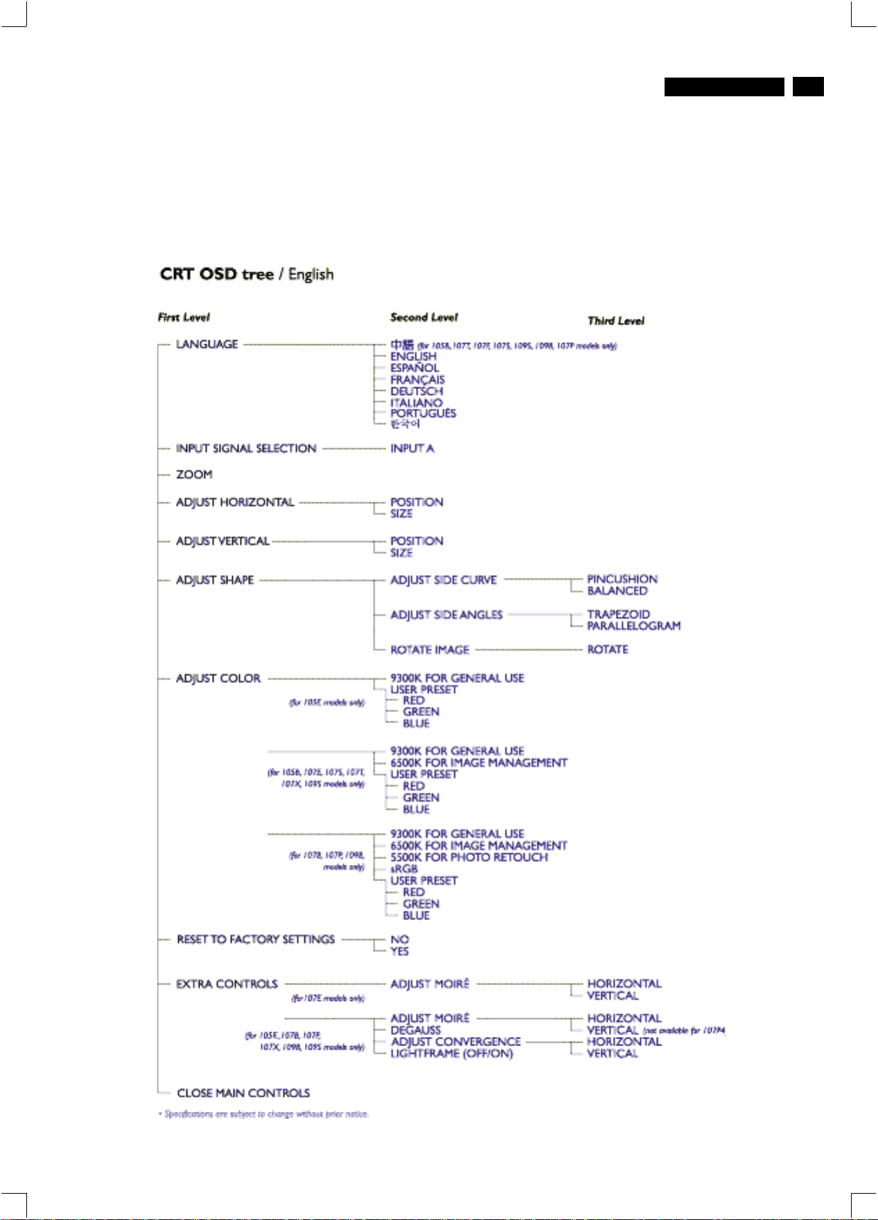
The OSD Tree
Below is an overall view of the structure of the On-Screen
Display. You can use this as reference when you want to
later on work your way around the different adjustments.
V20 107E5
Go to cover page
9
5
Page 6
6
http://jdwxzlw.5d6d.com/?fromuser=华盛维修
家电维修资料网,免费下载各种维修资料
9
V20 107E5
Go to cover page
OSD Adjustments
The OSD Controls
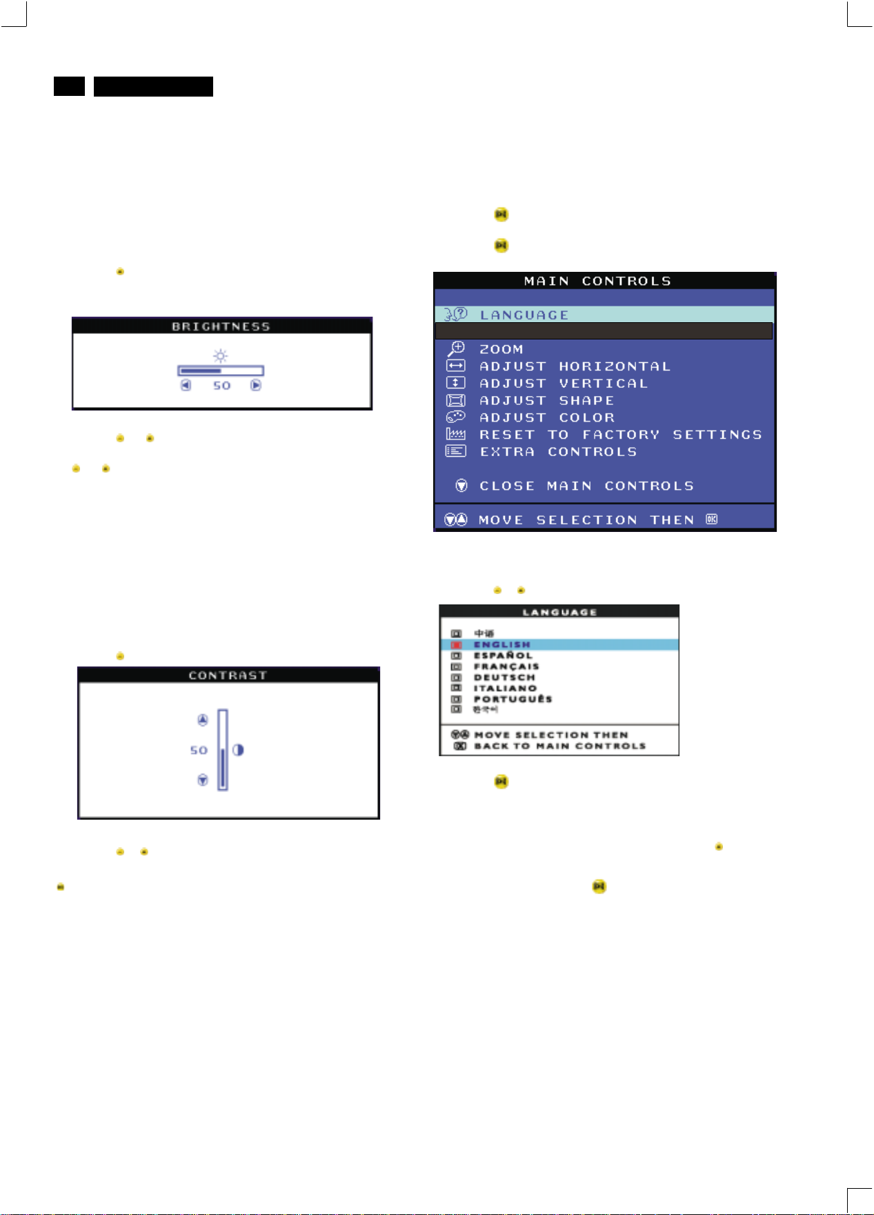
BRIGHTNESS
To adjust your screen's brightness, follow the steps below. Brightness is
the overall intensity of the light coming from the screen. A 50%
brightness is recommended.
1) Press the button on the monitor. The BRIGHTNESS window
appears.
2) Press the or button to adjust the brightness.
3) When the brightness is adjusted to the level desired, stop pressing
the or button and after three seconds the BRIGHTNESS window
will disappear with the new adjustment saved.
Smart Help
continue to the CONTRAST window, follow the steps under CONTRAST.
After the BRIGHTNESS window has disappeared, to
LANGUAGE
The ON SCREEN DISPLAY shows its settings in one of five languages.
The default is English, but you can select French, Spanish, German, or
Italian.
1) Press the button on the monitor. The MAIN CONTROLS window
appears. LANGUAGE should be highlighted.
2) Press the button again. The LANGUAGE window appears.
CONTRAST
To adjust your screen's contrast, follow the steps bellow. Contrast is the
difference between the light and dark areas on the screen. A 100%
contrast is recommended.
1) Press the button on the monitor. The CONTRAST window appears.
2) Press the or button to adjust the contrast.
3) When the contrast is adjusted to the level desired, stop pressing the
Button and after three seconds the CONTRAST window will
disappear with the new adjustment saved.
Smart Help
continue to the MAIN CONTROLS, follow the steps under LANGUAGE
After the CONTRAST window has disappeared, to
3) Press the or button until the desired language is highlighted.
4) Press the button to confirm your selection and return to MAIN
CONTROLS window. CLOSE MAIN CONTROLS will be highlighted...
Smart Help
...tocontinue to INPUT SIGNAL SELECTION, press the button until
INPUT SIGNAL SELECTION is highlighted. Next, follow steps3-5
under INPUT SIGNAL SELECTION.
...toexit completely, press the button
After returning to MAIN CONTROLS...
Page 7
OSD Adjustments (Continued)
http://jdwxzlw.5d6d.com/?fromuser=华盛维修
家电维修资料网,免费下载各种维修资料
V20 107E5
Go to cover page
9
7
ZOOM
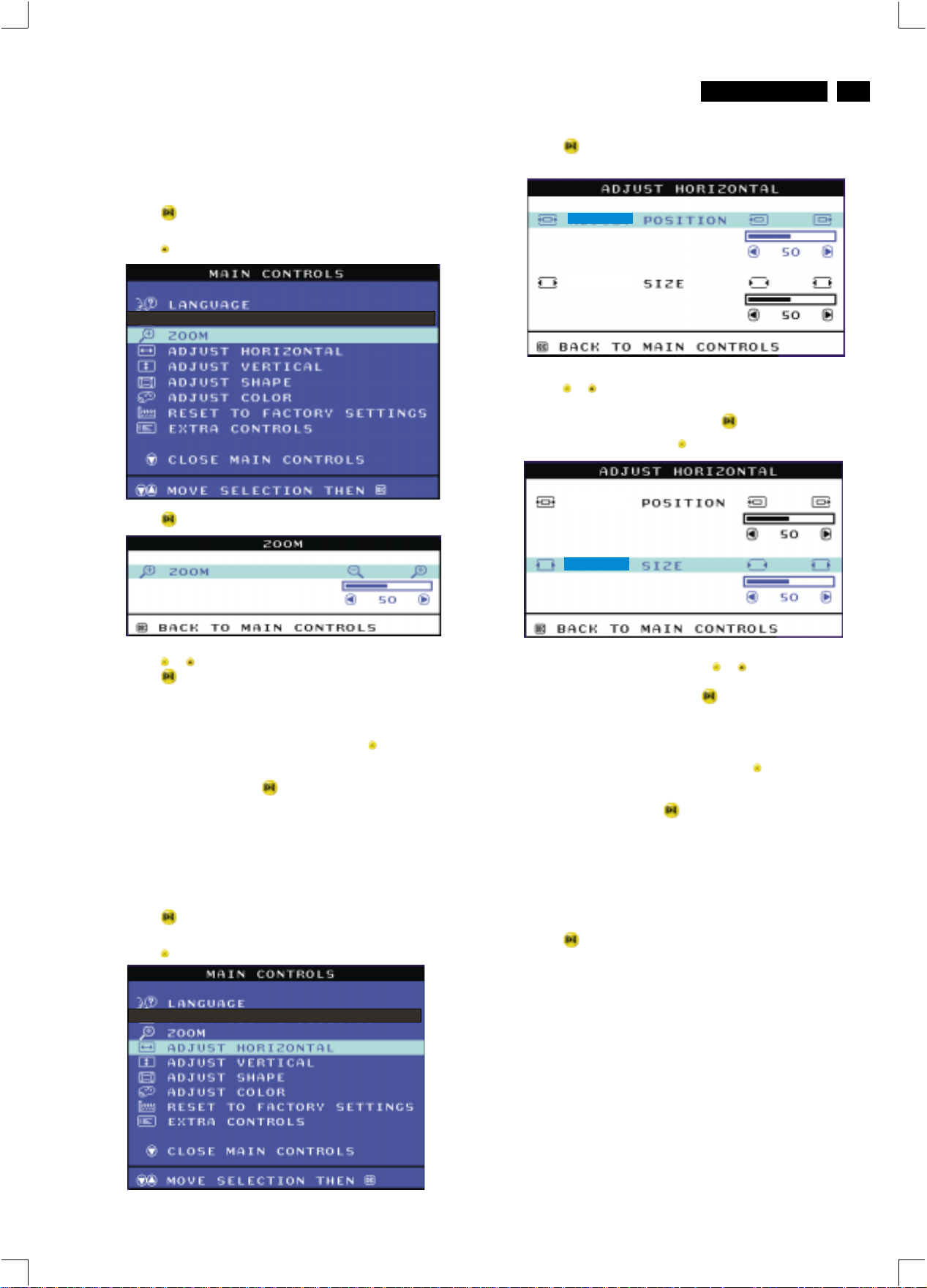
ZOOM increases or decreases the size of the images on your screen.
To adjust the ZOOM follow the steps below.
1) Press the button on the monitor. The MAIN CONTROLS window
appears.
2) Press the button until ZOOM is highlighted.
3) Press the button. The ZOOM window appears.
3) Press the button. The ADJUST HORIZONTAL window appears.
ADJUST POSITION should be highlighted.
4) Press the or button to move the image to the left or right.
5) When the position is adjusted, press the button to return to MAIN
CONTROLS window, or press the to highlight ADJUST SIZE.
4) Press the or button to adjust ZOOM.
5) Press the button to confirm your selection and return to the MAIN
CONTROLS window. CLOSE MAIN CONTROLS will be highlighted.
Smart Help
...tocontinue to ADJUST HORIZONTAL, press the button until
ADJUST HORIZONTAL is highlighted. Next, follow steps3-7under
ADJUST HORIZONTAL.
...toexit completely, press the button
ADJUST HORIZONTAL
ADJUST POSITION under ADJUST HORIZONTAL shifts the image on
your screen either to the left or right. Use this feature if your image does
not appear centered. ADJUST SIZE under ADJUST HORIZONTAL
expands or controls the image on your screen, pushing it out toward the
left and right sides or pulling it in toward the center.
1) Press the button on the monitor. The MAIN CONTROLS window
appears.
2) Press the button until ADJUST HORIZONTAL is highlighted.
After returning to MAIN CONTROLS...
6) To adjust the horizontal size, press the or button.
7) When the size is adjusted, press the button to return to MAIN
CONTROLS window. CLOSE MAIN CONTROLS will be highlighted.
Smart Help
...tocontinue to ADJUST VERTICAL, press the button until ADJUST
VERTICAL is highlighted. Next, start with step 3 under ADJUST
VERTICAL and follow the directions.
...toexit completely, press the button
ADJUST VERTICAL
ADJUST POSITION under ADJUST VERTICAL shifts the image on
your screen either up or down. Use this feature if your image does not
appear centered. ADJUST SIZE under ADJUST VERTICAL expands or
controls the image on your screen, pushing it out toward the top or
bottom or pulling it in toward the center.
1) Press the button on the monitor. The MAIN CONTROLS window
appears.
After returning to MAIN CONTROLS...
Page 8
8
http://jdwxzlw.5d6d.com/?fromuser=华盛维修
家电维修资料网,免费下载各种维修资料
Go to cover page
9
V20 107E5
OSD Adjustments (Continued)
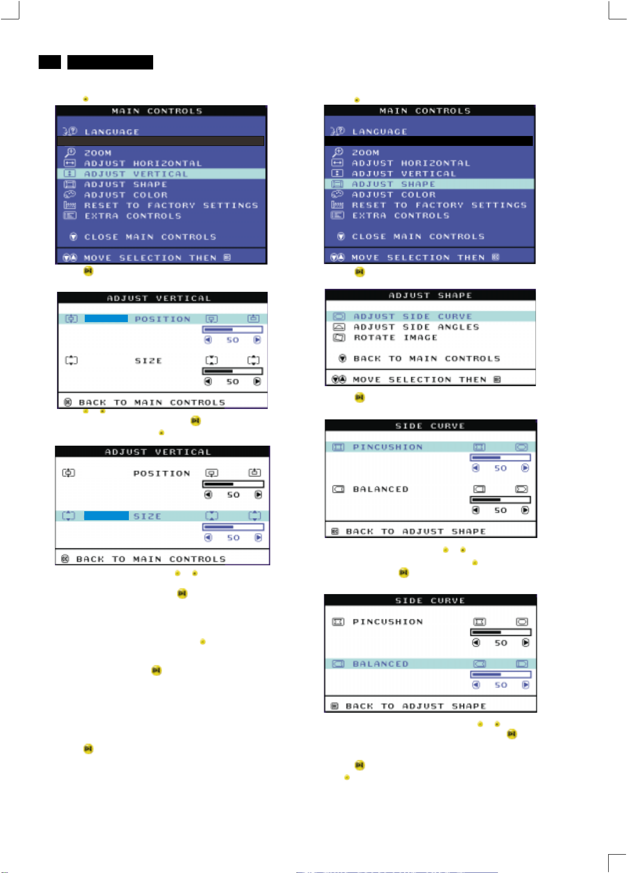
2) Press the button until ADJUST VERTICAL is highlighted.
3) Press the button. The ADJUST VERTICAL window appears.
ADJUST POSITION should be highlighted.
2) Press the button until ADJUST SHAPE is highlighted.
3) Press the button. The ADJUST SHAPE window appears.
ADJUST SIDE CURVE should be highlighted.
4) Press the or button to move the image up or down.
5) When the position is adjusted, press the button to return to MAIN
CONTROLS window, or press the button to highlight ADJUST SIZE.
6) To adjust the vertical size, press the or button.
7) When the size is adjusted, press the button to return to MAIN
CONTROLS window. CLOSE MAIN CONTROLS will be highlighted.
Smart Help
...tocontinue to ADJUST SHAPE, press the button until ADJUST
SHAPE is highlighted. Next, start with step 3 under ADJUST SHAPE
and follow the directions.
...toexit completely, press the button
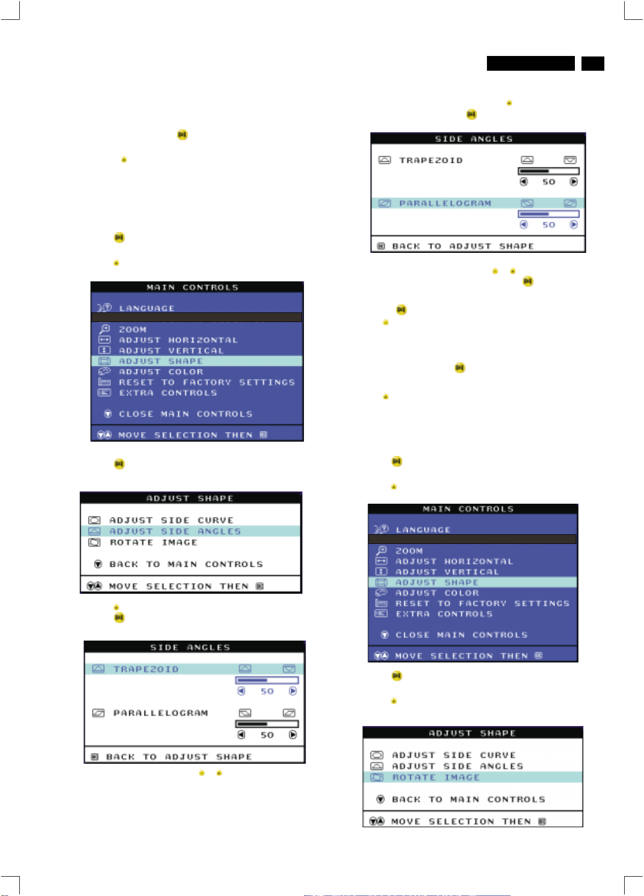
ADJUST SHAPE
ADJUST SIDE CURVE
ADJUST SIDE CURVE under ADJUST SHAPE allows you to adjust two
of the five preset options. These two options are PINCUSHION and
BALANCED pincushion. Note: use these features only when the picture
is not square.
1) Press the button on the monitor. The MAIN CONTROLS window
appears.
After returning to MAIN CONTROLS...
4) Press the button. The SIDE CURVE window appears.
PINCUSHION should be highlighted.
5) To adjust the pincushion, press the or button.
6) When the pincushion is adjusted, press the button to highlight
BALANCED or press the button to return to the ADJUST SHAPE
window.
7) To adjust the balanced pincushion, press the or button.
8) When the balanced pincushion is adjusted, press the button to
return to the ADJUST SHAPE window. BACK TO MAIN WINDOWS will
be highlighted.
9) Press the button to return to the MAIN CONTROLS window, or
press the button until ADJUST SIDE ANGLES is highlighted.
Page 9
OSD Adjustments (Continued)
http://jdwxzlw.5d6d.com/?fromuser=华盛维修
家电维修资料网,免费下载各种维修资料
V20 107E5
Go to cover page
9
9
Smart Help After returning to MAIN CONTROLS...
...to continue to ADJUST SIDE ANGLES, start with step 5 under
ADJUST SIDE ANGLES and follow the directions.
...to exit completely, press the button twice.
...to adjust only the BALANCED pincushion, follow steps1-4above,
then press the button, and follow steps7-9.
ADJUST SIDE ANGLES
ADJUST SIDE ANGLES under ADJUST SHAPE allows you to adjust
two of the five preset options. These two options are TRAPEZOID and
PARALLELOGRAM. Note: use these features only when the picture is
not square.
1) Press the button on the monitor. The MAIN CONTROLS window
appears.
2) Press the button until ADJUST SHAPE is highlighted.
3) Press the button. The ADJUST SHAPE window appears.
ADJUST SIDE CURVE should be highlighted.
7) When the trapezoid is adjusted, press the button to highlight
PARALLELOGRAM or press the button to return to the ADJUST
SHAPE window.
8) To adjust the parallelogram, press the or button.
9) When the parallelogram is adjusted, press the button to return to
the ADJUST SHAPE window. BACK TO MAIN WINDOWS will be
highlighted.
10) Press the button to return to the MAIN CONTROLS window, or
press the button until ROTATE IMAGE is highlighted.
Smart Help
...to continue to ROTATE IMAGE, start with step 5 under ROTATE
IMAGE and follow the directions.
...to exit completely, press the button twice.
...to adjust only the PARALLELOGRAM, follow steps1-4above, then
press the button, and follow steps 7 -9
ROTATE IMAGE
ROTATE IMAGE under ADJUST SHAPE allows you to adjust one of
the five preset options. These two options are PINCUSHION and
BALANCED pincushion. Note: use this feature only when the picture is
not square.
1) Press the button on the monitor. The MAIN CONTROLS window
appears.
2) Press the button until ADJUST SHAPE is highlighted.
After returning to MAIN CONTROLS...
4) Press the button to highlight ADJUST SIDE ANGLES.
5) Press the button. The SIDE ANGLES window appears.
TRAPEZOID should be highlighted.
3) Press the button. The ADJUST SHAPE window appears.
ADJUST SIDE CURVE should be highlighted.
4) Press the arrow until ROTATE IMAGE is highlighted.
6) To adjust the trapezoid, press the or button.
Page 10
10
http://jdwxzlw.5d6d.com/?fromuser=华盛维修
家电维修资料网,免费下载各种维修资料
Go to cover page
9
V20 107E5
OSD Adjustments (Continued)
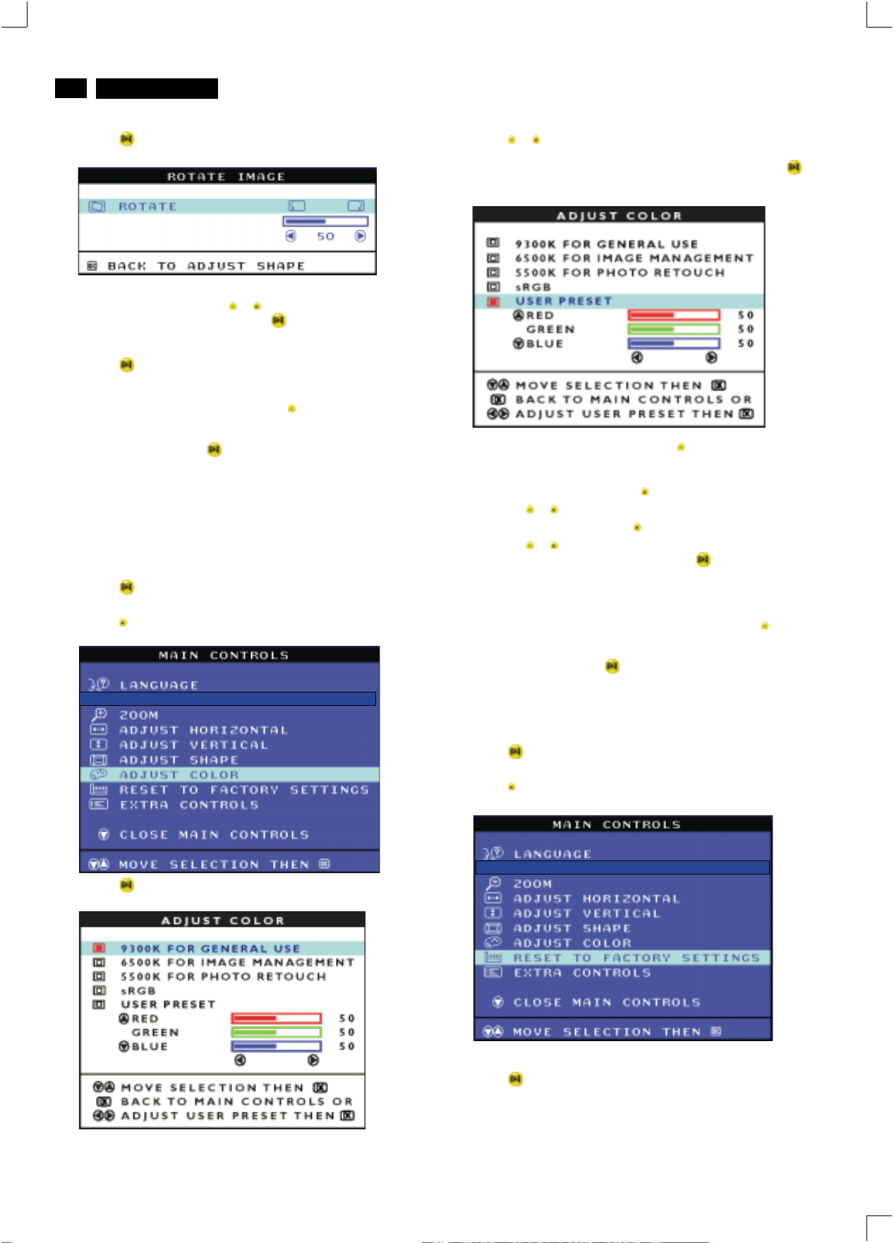
5) Press the button. The ROTATE IMAGE window appears. ROTATE
should be highlighted.
6) To adjust the rotation, press the or button.
7) When the rotation is adjusted, press the button to return to the
ADJUST SHAPE window. BACK TO MAIN CONTROLS should be
highlighted.
8) Press the button to return to MAIN CONTROLS.
Smart Help
...tocontinue to ADJUST COLOR, press the button until ADJUST
COLOR is highlighted. Next, start with step 3 under ADJUST COLOR
and follow the directions.
...to exit completely, press the button twice.
ADJUST COLOR
Your monitor has two preset options you can choose from. The first
option is for GENERAL USE, which is fine for most applications. The
second option is for GAMES, which is for playing computer games.
When you select one of these options, the monitor automatically adjusts
itself to that option. There is also a third option, USER PRESET, which
allows you to adjust the colors on your screen to a setting you desire.
1) Press the button on the monitor. The MAIN CONTROLS window
appears.
2) Press the button until ADJUST COLOR is highlighted.
After returning to MAIN CONTROLS...
4) Press the or button to highlight 9300K for GENERAL USE,
6500K for GAMES, or USER PRESET.
5) Once you have highlighted GENERAL USE or GAMES, press the
button to confirm you selection and return to the MAIN CONTROLS
window. CLOSE MAIN CONTROLS will be highlighted.
6a) If USER PRESET is highlighted, press the button to highlight RED.
Next, press the LEFT CURSOR or RIGHT CURSOR button to adjust the
color red.
6b) When finished with RED, press the button to highlight GREEN.
Next, press the or button to adjust the color green.
6c) When finished GREEN, press the button to highlight BLUE.
Next, press the or button to adjust the color blue.
6d) When all adjustments are complete, press the button to confirm
your adjustments and return to the MAIN CONTROLS window. CLOSE
MAIN CONTROLS will be highlighted.
Smart Help
...tocontinue to RESET TO FACTORY SETTINGS, press the button
until RESET TO FACTORY SETTINGS is highlighted. Next, start with
step 3 under RESET TO FACTORY SETTINGS.
...toexit completely, press the button.
After returning to MAIN CONTROLS. . .
3) Press the button. The ADJUST COLOR window appears.
RESET TO FACTORY SETTINGS
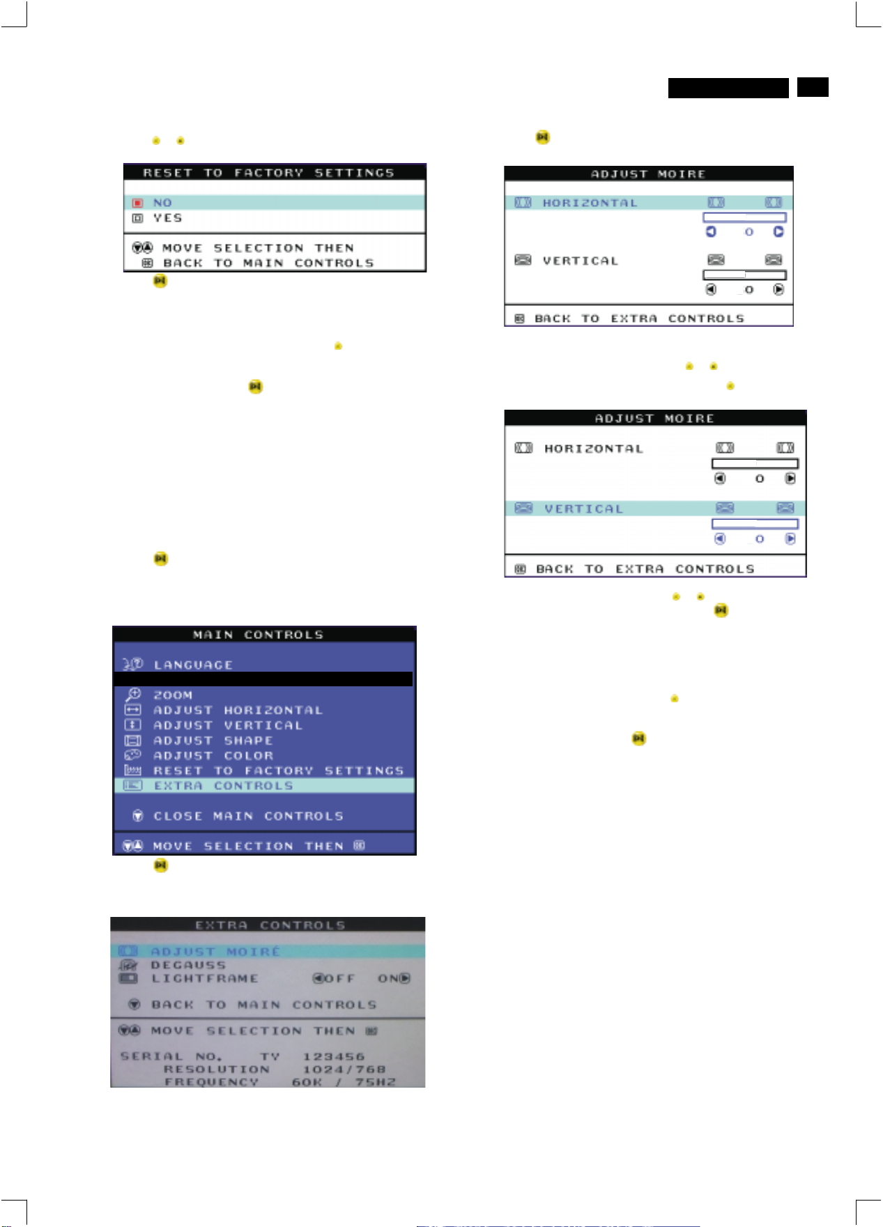
RESET TO FACTORY SETTINGS returns everything in all the windows
to factory presets.
1) Press the button on the monitor. The MAIN CONTROLS window
appears.
2) Press the button until RESET TO FACTORY SETTINGS is
highlighted.
3) Press the button. The RESET TO FACTORY SETTINGS window
appears.
Page 11
OSD Adjustments (Continued)
http://jdwxzlw.5d6d.com/?fromuser=华盛维修
家电维修资料网,免费下载各种维修资料
V20 107E5
Go to cover page
9
11
4) Press the or button to select YES or NO. NO is the default. YES
returns all settings to their original factory adjustments.
5) Press the button to confirm your selection and return to the MAIN
CONTROLS window. CLOSE MAIN CONTROLS will be highlighted.
Smart Help
...tocontinue to EXTRA CONTROLS, press the button until EXTRA
CONTROLS is highlighted. Next, start with step 3 under EXTRA
CONTROLS.
...toexit completely, press the button.
EXTRA CONTROLS
ADJUST MOIRE
EXTRA CONTROLS is a set of three features, including ADJUST
MOIRE. Moire is a fringe pattern arising from the interference between
two superimposed line patterns. To adjust your moire, follow the steps
below. Note: Use only if necessary. By activating ADJUST MOIRE,
sharpness can be affected.
After returning to MAIN CONTROLS...
4) Press the button. The ADJUST MOIRE window appears.
HORIZONTAL will be highlighted.
5) To adjust the horizontal moire, press the or button.
6) When the horizontal moire is adjusted, press the button to highlight
VERTICAL.
1) Press the button on the monitor. The MAIN CONTROLS window
appears.
2) Press the DOWN CURSOR button until EXTRA CONTROLS is
highlighted.
3) Press the button. The EXTRA CONTROLS window appears. will
be highlighted.ADJUST MOIRE will
7) To adjust the vertical moire, press the or button.
8) When the vertical moire is adjusted, press the button to return to
the EXTRA CONTROLS window. BACK TO MAIN CONTROLS will be
highlighted.
Smart Help After returning to MAIN CONTROLS...
...tocontinue to DEGAUSS, press the button until is
highlighted. Next, start with step 3 under EXTRA CONTROLS,
DEGAUSS.
...toexit completely, press the button.
DEGAUSS
Page 12
12
http://jdwxzlw.5d6d.com/?fromuser=华盛维修
家电维修资料网,免费下载各种维修资料
Go to cover page
9
V20 107E5
OSD Adjustments (Continued), Troubleshooting
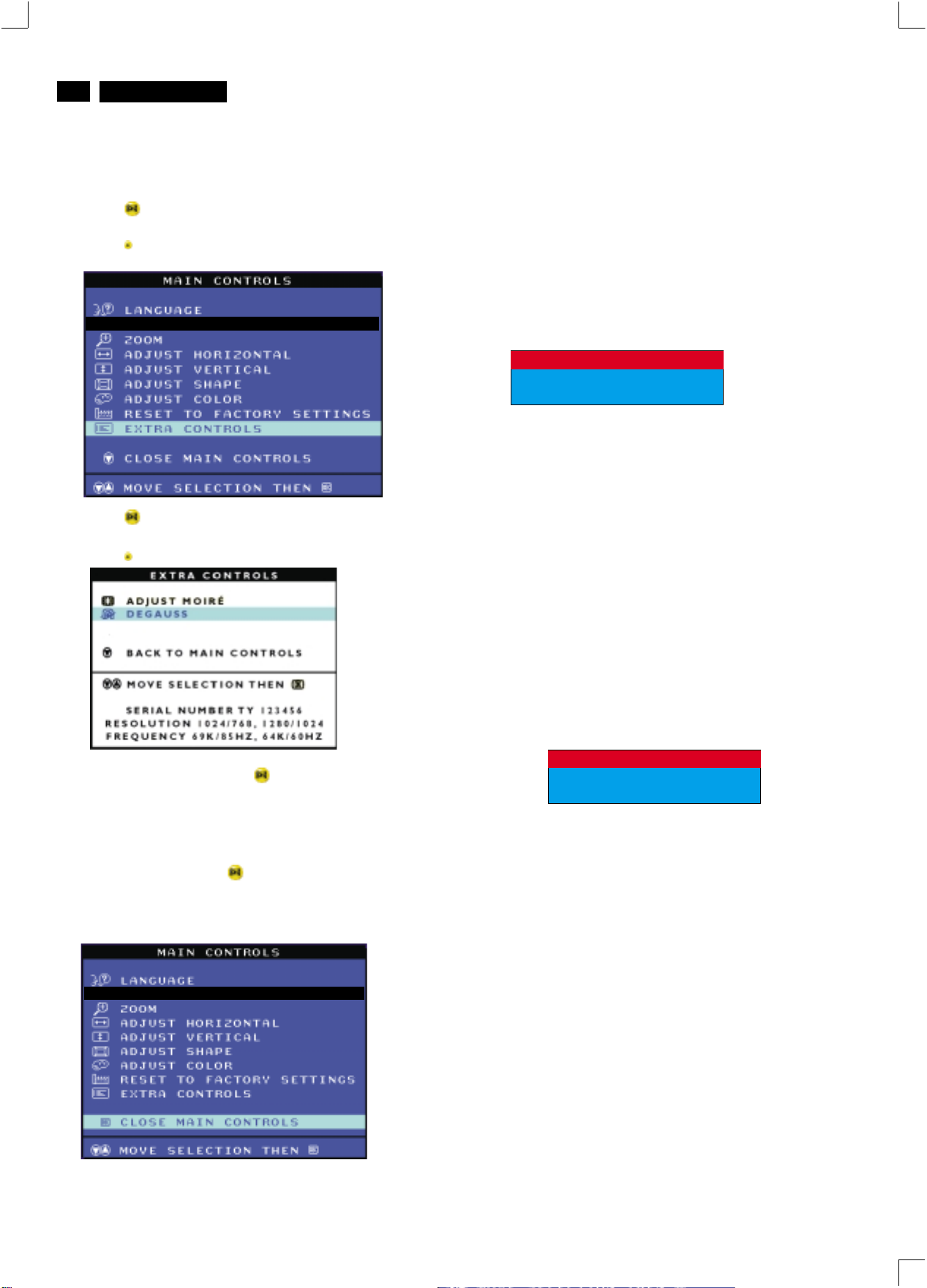
DEGAUSS
EXTRA CONTROLS is a set of three features, including DEGAUSS.
Degaussing removes electromagnetic build up that may distort the color
on your screen.
1) Press the button on the monitor. The MAIN CONTROLS window
appears.
2) Press the button until EXTRA CONTROLS is highlighted.
3) Press the button. The EXTRA CONTROLS window appears.
ADJUST MOIRE will be highlighted.
4) Press the button until DEGAUSS is highlighted.
Monitor Specific Troubleshooting
Self-Test Feature Check (STFC)
Your monitor provides a self-test feature that allows you to check
whether your monitor is functioning properly. If your monitor and
computer are properly connected but the monitor screen remains
dark, run the monitor self-test by performing the following steps:
1. Turn off both your computer and the monitor.
2. Unplug the video cable from the back of the computer.
3. Turn on the monitor.
If the monitor is functioning properly, you will see a OSD
message as shown in the following illustration:
ATTENTION
CHECK SIGNAL CABLE
This box also appears during normal system operation if the
video cable becomes disconnected or damaged. This box
will remain on for one minute, go off five seconds, then on for
one minute, and will repeat cycle.
1. Turn off your monitor and reconnect the video cable;
then turn on both your computer and the monitor.
2. While in self-test mode, the LED remains green and the
pattern remains on and stationary.
If your monitor screen still remains dark after you use the
previous procedure, check your video controller and computer
system; your monitor is functioning properly.
5) To degauss your screen, press the button. Your screen will be
degaussed, then the MAIN CONTROLS window will reappear. CLOSE
MAIN CONTROLS will be highlighted.
Smart Help After returning to MAIN CONTROLS...
...toexit completely, press the button.
CLOSE MAIN CONTROLS
NO SIGNAL INPUT
If there is something wrong with the input signal, a message
appears on the screen although the power indicator LED is
still on. The message may indicate that the monitor is NO
SIGNAL INPUT or that you need to check the signal cable.
ATTENTIONATTENTION
NO SIGNAL INPUT
Page 13
Lock/Unlock, Factory Mode, Burn In, Service Mode
http://jdwxzlw.5d6d.com/?fromuser=华盛维修
家电维修资料网,免费下载各种维修资料
V20 107E5
Go to cover page
9
13
FrontControl
Power button switches your monitor on.
OK button which when pressed will take you to the OSD
controls
Contrast hotkey. When the "-" button is pressed,
the adjustment controls for the CONTRAST will show up.
Brightness hotkey. When the "+" button is pressed,
the adjustment controls for BRIGHTNESS will show up.
"-" and "+" buttons, are used for adjusting the OSD of your
monitor.
To access factory mode
1. Turn off monitor (don't turn off PC)
2. Press '" " and " " simultaneously on the front control
panel,then press " ",wait till the OSD menu with characters
V20 107E5 V0.20 20021217 (below OSD menu)" come on the
screen of monitor.
Factory
Mode
Indicator
3. If OSD menu disappears on the screen of monitor, press " "
again (anytime), then the OSD menu comes on the screen again.
4. Using " " : to select OSD menu.
5. Using " " : to increase or decrease the setting.
6. Using " " to access/confirm the selection.
MODEL SELECT
V20 107E5 V0.20 20021217
OSD Lock
OSD lock is a feature which disables the OSD controls. It can be used
when the monitor is set up for demonstration purposes or when
adjustment of the OSD is not desirable.
Switch on OSD lock feature:
Press and hold the button continuously for 15 seconds.
Release the button when the message
"CONTROL MENU IS LOCKED" appears.
Switch off OSD lock feature:
Press and hold the button continuously for 15 seconds or until the
message window "CONTROL MENU IS LOCKED" disappears, and
"MAIN CONTROLS" appears.
To leave factory mode
7. After alignment of factory mode, turn off monitor (if you do not turn
off monitor, the OSD menu is always at the factory mode), then
turn on monitor again (at this moment, the OSD menu goes back
to user mode).
To access BURN IN mode
First of all, monitor displays an image.
1. Disconnect the video cable (interface cable).
2. Turn off monitor
3. Press '" " and " " simultaneously on the front control
panel,then the BURN IN mode comes on the screen of monitor
as below.
50 seconds around
5 seconds around
repeatly
Reconnect the video cable, then return to normal image.
4.
SERVICE MODE (Indication-Factory mode)
00010
Default setting of MODEL SELECT (Do not change it.)
MODEL SELECT
107E5 ORION
107E5 NORMAL
RESERVE
RESERVE
RESERVE
SWDDC
MODEL SELECT
V20 107E5 V0.20 20021217
------------------------>
00010: stands for
1. using 10 hours already.
2. turn on/off 10 times.
3. using several hours
+ turn on/off monitor.
Page 14
14
http://jdwxzlw.5d6d.com/?fromuser=华盛维修
家电维修资料网,免费下载各种维修资料
X
V20 107E5
Go to cover page
Warning and Notes
Warnings
. Safety regulations require that the unit should be returned
1
in its original condition and that components identical to
the original components are used. The safety components
are indicated by the symbol .
. In order to prevent damage to ICs and transistors, all
2
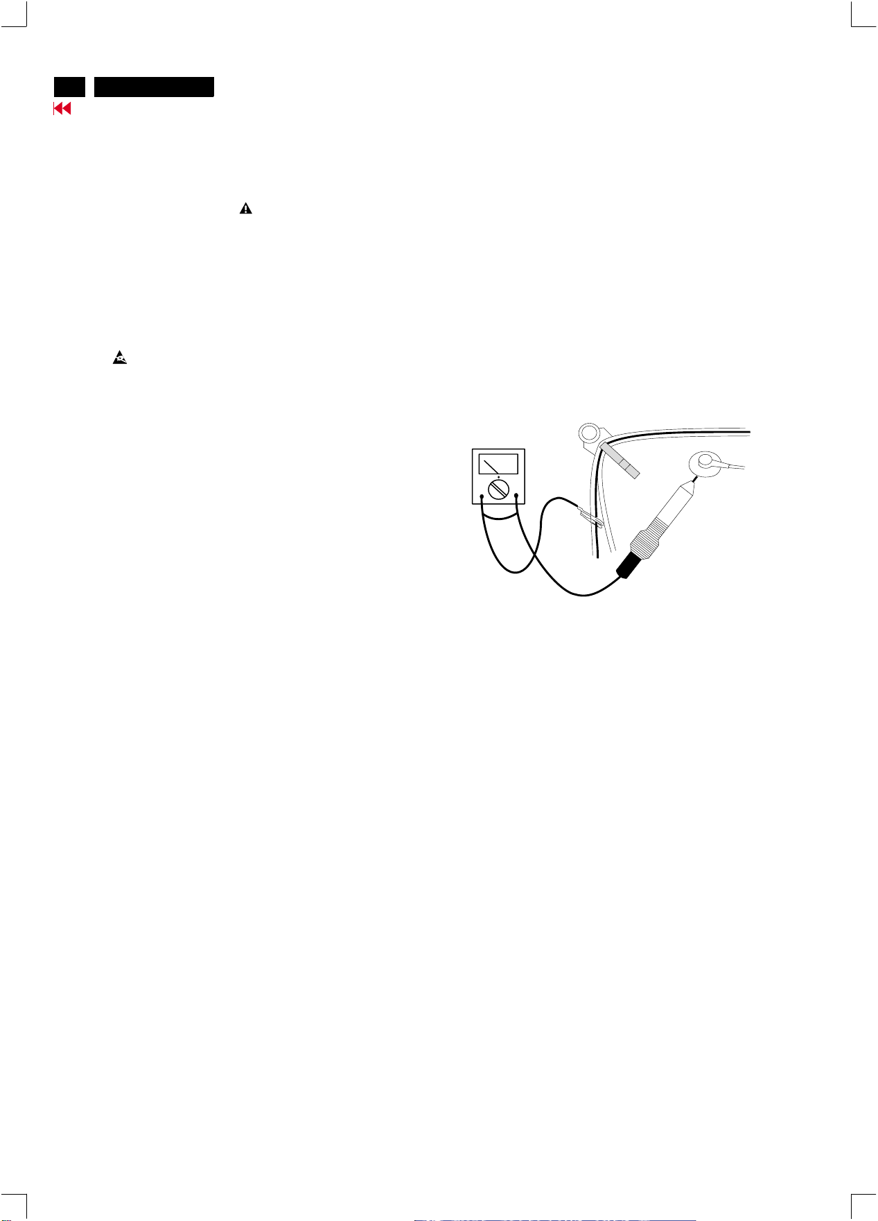
high-voltage flash-overs must be avoided. In order to
prevent damage to the picture tube, the method shown
in Fig. 1 should be used to discharge the picture tube.
Use a high-voltage probe and a multimeter (position DC-V).
Discharge until the meter reading is (after approximately
30 seconds).
.
3 ESD
All ICs and many other semiconductors are sensitive to
electrostatic discharges (ESD). Careless handling during
repair can drastically shorten their life. Make sure that
during repair you are connected by a pulse band with
resistance to the same potential as the ground of the unit.
Keep components and tools also at this same potential.
. When repairing a unit, always connect it to the AC Power
4
voltage via an isolating transformer.
. Be careful when taking measurements in the high-voltage
5
section and on the picture tube panel.
0V
Notes
The direct voltages and waveforms are average voltages.
1.
They have been measured using the Service test software
and under the following conditions :
- Mode : 640 * 480 (31.5kHz / 60Hz)
- Signal pattern : grey scale
- Adjust brightness and contrast control for the
mechanical mid-position (click position)
The picture tube panel has printed spark gaps.
2.
Each spark gap is connected between an electrode of the
picture tube and the Aquadag coating.
The semiconductors indicated in the circuit diagram(s)
3.
and in the parts lists are completely interchangeable per
position with the semiconductors in the unit, irrespective
of the type indication on these semiconductors.
V
. It is recommended that saferty goggles be worn when
6
replacing the picture tube.
. When making adjustments,use plastic rather than metal tools.
7
This will prevent any short-circuit or the danger of a
circuit becoming unstable.
. Never replace modules or other components while the
8
unit is switched on.
. Together with the defleciton unit, the picture tube is used
9
as an integrated unit. Adjustment of this unit during repair
is not recommended.
After repair, the wiring should be fastened in place with
10.
the cable clamps.
All units that are returned for service or repair must pass
11.
the original manufactures safety tests.
Fig.1
Page 15
Mechanical Instructions
http://jdwxzlw.5d6d.com/?fromuser=华盛维修
家电维修资料网,免费下载各种维修资料
0. General
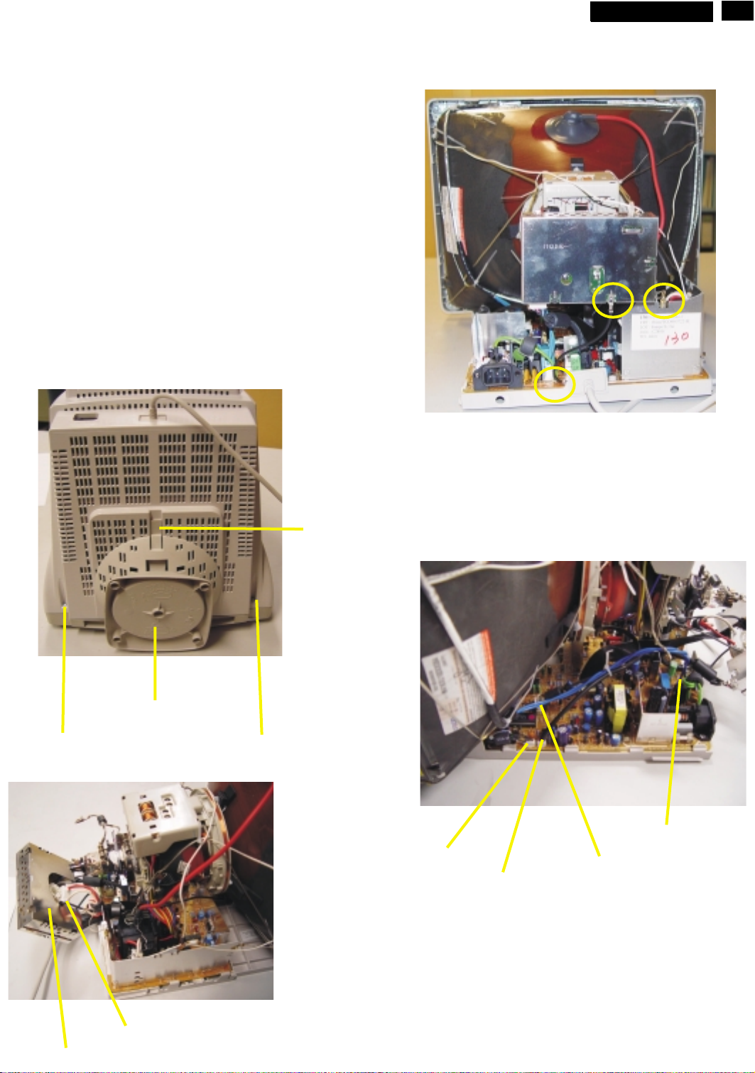
To be able to perform measurements and repairs on the "circuit
boards", these unit should placed in the service position first.
1.Remove the rear cover in Fig. 1.
-Remove 2 screws as shown
-Remove back cover as shown
-Remove pedestal as shown
2. Video panel
- Disconnect the wire between metal shield of Video panel and
CRT neck as shown in Fig. 2.
- Disconnect the CRT ground "1703" from Video panel.
- Remove screw grounding and grounding wire in Fig. 3.
3.Main board connector in Fig. 4
-Disconnect york wire from "1601"
-Disconnect rotation connector "1401"
-Disconnect control board connector "1803"
-Remove Screw for fixed I/F cable
-Remove signal connector "1802"
-Remove degaussing wire connector "1103"
V20 107E5
9
Go to cover page
15
Screw
Pedestal ass'y
Fig. 1
Screw
Clip
Control connector
Rotation connector
===============>
screw - grounding
Fig. 3
Degaussing wire connector
Signal connector
CRT grouding wirel
Video Panel
Fig. 2
Fig. 4
Page 16
16
http://jdwxzlw.5d6d.com/?fromuser=华盛维修
家电维修资料网,免费下载各种维修资料
V20 107E5
Mechanical Instructions
Go to cover page
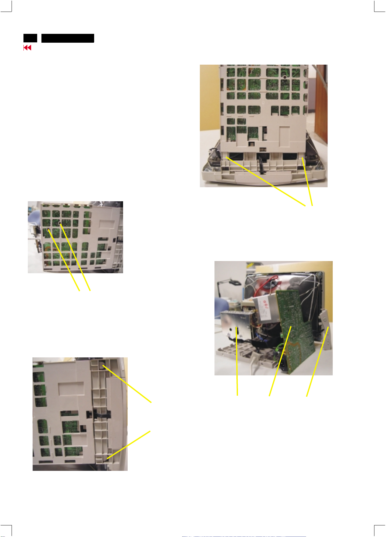
4. Main panel with Bottom Tray
-Remove 2 screws for disconnect the Bottom tray as Fig. 5.
-Pull the bottom tray from fig. 6
to fig. 7.
5. SERVICE POSITION
Reconnect connectors, some wires and panels (chassis),
service position can be available for DC/AC measurement
as shown in Fig. 8.
on press right and left side clip
Screw
Fig. 5
Fig. 7
=======>
Pull-up
Video panel
Press CLIP
Fig. 6
Fig. 8 SERVICE POSITION
Main panel
Front control
panel
Page 17
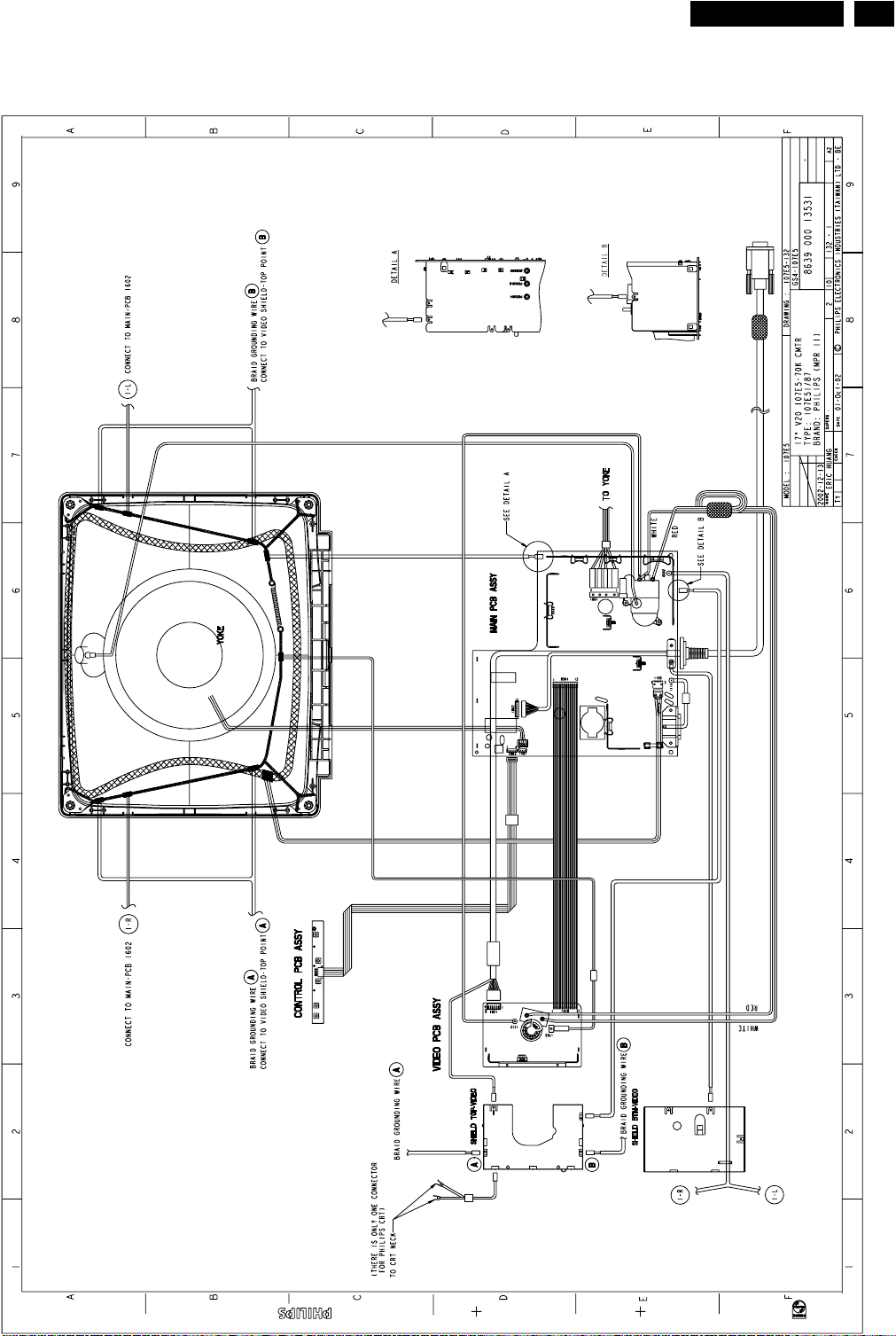
Wiring Diagram
http://jdwxzlw.5d6d.com/?fromuser=华盛维修
家电维修资料网,免费下载各种维修资料
V20 107E5
9
Go to cover page
17
Page 18

18
http://jdwxzlw.5d6d.com/?fromuser=华盛维修
家电维修资料网,免费下载各种维修资料
V20 107E5
Go to cover page
Hex Data of DDC2B
**********************************************************************
107E5 Orion Tube EDID log file
**********************************************************************
Vendor/Product Identification
ID Manufacturer Name : PHL
ID Product Code : 000D(HEX.)
ID Serial Number : 4D2 (HEX.)
Week of Manufacture : 42
Year of Manufacture : 2002
EDID Version, Revision
Version : 1
Revision : 3
Basic Display Parameters/Features
Video Input Definition : Analog Video Input
0.700V/0.000V (0.70Vpp)
without Blank-to-Black Setup
Separate Sync
without Composite Sync
without Sync on Green
no Serration required
Maximum H Image Size : 31
Maximum V Image Size : 23
Display Transfer Characteristic : 2.98
(gamma)
Feature Support (DPMS): Standby
Suspend
Active Off
Display Type : RGB color display
Color Characteristics
Red X coordinate : 0.645
Red Y coordinate : 0.322
Green X coordinate : 0.278
Green Y coordinate : 0.602
Blue X coordinate : 0.142
Blue Y coordinate : 0.06
White X coordinate : 0.283
White Y coordinate : 0.297
Established Timings
Established Timings I : 720 x 400 @70Hz (IBM,VGA)
640 x 480 @60Hz (IBM,VGA)
640 x 480 @72Hz (VESA)
640 x 480 @75Hz (VESA)
800 x 600 @60Hz (VESA)
Established Timings II : 800 x 600 @72Hz (VESA)
800 x 600 @75Hz (VESA)
832 x 624 @75Hz (Apple,Mac II)
1024 x 768 @60Hz (VESA)
1024 x 768 @70Hz (VESA)
1024 x 768 @75Hz (VESA)
Manufacturer's timings :
Standard Timing Identification #1
Horizontal active pixels : 640
Aspect Ratio : 4:3
Refresh Rate : 85
Standard Timing Identification #6
Horizontal active pixels : 800
Aspect Ratio : 4:3
Refresh Rate : 100
Standard Timing Identification #7
Horizontal active pixels : 1280
Aspect Ratio : 4:3
Refresh Rate : 60
Standard Timing Identification #8
Horizontal active pixels : 1152
Aspect Ratio : 4:3
Refresh Rate : 75
Detailed Timing #1
Pixel Clock (MHz) : 25.18
H Active (pixels) : 640
H Blanking (pixels) : 160
V Active (lines) : 350
V Blanking (lines) : 99
H Sync Offset (F Porch) (pixels): 16
H Sync Pulse Width (pixels): 96
V Sync Offset (F Porch) (lines) : 37
V Sync Pulse Width (lines) : 2
H Image Size (mm) : 306
V Image Size (mm) : 230
H Border (pixels) : 0
V Border (lines) : 0
Flags : Non-interlaced
: Normal Display, No stereo
: Digital Separate sync.
: Negative Vertical Sync.
: Positive Horizontal Sync.
Monitor Descriptor #2
Serial Number : TY 123456
Monitor Descriptor #3
Monitor Name : PHILIPS 107E5
Monitor Descriptor #4
Monitor Range Limits
Min. Vt rate Hz : 50
Max. Vt rate Hz : 160
Min. Horiz. rate kHz : 30
Max. Horiz. rate kHz : 71
Max. Supported Pixel : 110
No secondary GTF timing formula supported.
Extension Flag : 0
Check sum : 99 (HEX.)
**********************************************************************
107E5 Orion EDID data (128 bytes)
**********************************************************************
Standard Timing Identification #2
Standard Timing Identification #3
Standard Timing Identification #4
Standard Timing Identification #5
Horizontal active pixels : 800
Aspect Ratio : 4:3
Refresh Rate : 85
Horizontal active pixels : 1024
Aspect Ratio : 4:3
Refresh Rate : 85
Horizontal active pixels : 1280
Aspect Ratio : 5:4
Refresh Rate : 60
Horizontal active pixels : 640
Aspect Ratio : 4:3
Refresh Rate : 100
0: 00 1: ff 2: ff 3: ff 4: ff 5: ff 6: ff 7: 00
8: 41 9: 0c 10: 0d 11: 00 12: d2 13: 04 14: 00 15: 00
16: 2a 17: 0c 18: 01 19: 03 20: 08 21: 1f 22: 17 23: c6
24: e8 25: 24 26: 58 27: a5 28: 52 29: 47 30: 9a 31: 24
32: 0f 33: 48 34: 4c 35: ad 36: ee 37: 00 38: 31 39: 59
40: 45 41: 59 42: 61 43: 59 44: 81 45: 80 46: 31 47: 68
48: 45 49: 68 50: 81 51: 40 52: 71 53: 4f 54: d6 55: 09
56: 80 57: a0 58: 20 59: 5e 60: 63 61: 10 62: 10 63: 60
64: 52 65: 08 66: 32 67: e6 68: 10 69: 00 70: 00 71: 1a
72: 00 73: 00 74: 00 75: ff 76: 00 77: 20 78: 54 79: 59
80: 20 81: 20 82: 31 83: 32 84: 33 85: 34 86: 35 87: 36
88: 0a 89: 20 90: 00 91: 00 92: 00 93: fc 94: 00 95: 50
96: 48 97: 49 98: 4c 99: 49 100: 50 101: 53 102: 20 103: 31
104: 30 105: 37 106: 45 107: 35 108: 00 109: 00 110: 00 111: fd
112: 00 113: 32 114: a0 115: 1e 116: 47 117: 0b 118: 00 119: 0a
120: 20 121: 20 122: 20 123: 20 124: 20 125: 20 126: 00 127: 99
Address 78&79 factory code:
Brazil HC(48h,43h) Chungli TY(54h,59h)
Juarez YA(59h,41h) Shenzshen CX(43h,58h)
Suzhou BZ(42h,5Ah) Szombathely HD(48h,44h)
Page 19

Hex Data of DDC2B
http://jdwxzlw.5d6d.com/?fromuser=华盛维修
家电维修资料网,免费下载各种维修资料
V20 107E5
Go to cover page
19
**********************************************************************
107E5 LG Tube EDID log file
**********************************************************************
Vendor/Product Identification
ID Manufacturer Name : PHL
ID Product Code : 000D (HEX.)
ID Serial Number : 4D2 (HEX.)
Week of Manufacture : 42
Year of Manufacture : 2002
EDID Version, Revision
Version : 1
Revision : 3
Basic Display Parameters/Features
Video Input Definition : Analog Video Input
0.700V/0.000V (0.70Vpp)
without Blank-to-Black Setup
Separate Sync
without Composite Sync
without Sync on Green
no Serration required
Maximum H Image Size : 31
Maximum V Image Size : 23
Display Transfer Characteristic : 2.83
(gamma)
Feature Support (DPMS) : Standby
Suspend
Active Off
Display Type : RGB color display
Color Characteristics
Red X coordinate : 0.632
Red Y coordinate : 0.33
Green X coordinate : 0.273
Green Y coordinate : 0.605
Blue X coordinate : 0.142
Blue Y coordinate : 0.063
White X coordinate : 0.283
White Y coordinate : 0.297
Standard Timing Identification #6
Horizontal active pixels : 800
Aspect Ratio : 4:3
Refresh Rate : 100
Standard Timing Identification #7
Horizontal active pixels : 1280
Aspect Ratio : 4:3
Refresh Rate : 60
Standard Timing Identification #8
Horizontal active pixels : 1152
Aspect Ratio : 4:3
Refresh Rate : 75
Detailed Timing #1
Pixel Clock (MHz) : 25.18
H Active (pixels) : 640
H Blanking (pixels) : 160
V Active (lines) : 350
V Blanking (lines) : 99
H Sync Offset (F Porch) (pixels): 16
H Sync Pulse Width (pixels): 96
V Sync Offset (F Porch) (lines) : 37
V Sync Pulse Width (lines): 2
H Image Size (mm) : 306
V Image Size (mm) : 230
H Border (pixels) : 0
V Border (lines) : 0
Flags : Non-interlaced
: Normal Display, No stereo
: Digital Separate sync.
: Negative Vertical Sync.
: Positive Horizontal Sync.
Monitor Descriptor #2
Serial Number : TY 123456
Established Timings
Established Timings I : 720 x 400 @70Hz (IBM,VGA)
Established Timings II : 800 x 600 @72Hz (VESA)
Manufacturer's timings :
Standard Timing Identification #1
Horizontal active pixels : 640
Aspect Ratio : 4:3
Refresh Rate : 85
Standard Timing Identification #2
Horizontal active pixels : 800
Aspect Ratio : 4:3
Refresh Rate : 85
Standard Timing Identification #3
Horizontal active pixels : 1024
Aspect Ratio : 4:3
Refresh Rate : 85
Standard Timing Identification #4
Horizontal active pixels : 1280
Aspect Ratio : 5:4
Refresh Rate : 60
Standard Timing Identification #5
Horizontal active pixels : 640
Aspect Ratio : 4:3
Refresh Rate : 100
640 x 480 @60Hz (IBM,VGA)
640 x 480 @72Hz (VESA)
640 x 480 @75Hz (VESA)
800 x 600 @60Hz (VESA)
800 x 600 @75Hz (VESA)
832 x 624 @75Hz (Apple,Mac II)
1024 x 768 @60Hz (VESA)
1024 x 768 @70Hz (VESA)
1024 x 768 @75Hz (VESA)
Monitor Descriptor #3
Monitor Name : PHILIPS 107E5
Monitor Descriptor #4
Monitor Range Limits
Min. Vt rate Hz : 50
Max. Vt rate Hz : 160
Min. Horiz. rate kHz : 30
Max. Horiz. rate kHz : 71
Max. Supported Pixel : 110
No secondary GTF timing formula supported.
Extension Flag : 0
Check sum : ED(HEX)
**********************************************************************
107E5 LG EDID data (128 bytes)
**********************************************************************
0: 00 1: ff 2: ff 3: ff 4: ff 5: ff 6: ff 7: 00
8: 41 9: 0c 10: 0d 11: 00 12: d2 13: 04 14: 00 15: 00
16: 2a 17: 0c 18: 01 19: 03 20: 08 21: 1f 22: 17 23: b7
24: e8 25: e0 26: 58 27: a1 28: 54 29: 46 30: 9b 31: 24
32: 10 33: 48 34: 4c 35: ad 36: ee 37: 00 38: 31 39: 59
40: 45 41: 59 42: 61 43: 59 44: 81 45: 80 46: 31 47: 68
48: 45 49: 68 50: 81 51: 40 52: 71 53: 4f 54: d6 55: 09
56: 80 57: a0 58: 20 59: 5e 60: 63 61: 10 62: 10 63: 60
64: 52 65: 08 66: 32 67: e6 68: 10 69: 00 70: 00 71: 1a
72: 00 73: 00 74: 00 75: ff 76: 00 77: 20 78: 54 79: 59
80: 20 81: 20 82: 31 83: 32 84: 33 85: 34 86: 35 87: 36
88: 0a 89: 20 90: 00 91: 00 92: 00 93: fc 94: 00 95: 50
96: 48 97: 49 98: 4c 99: 49 100: 50 101: 53 102: 20 103: 31
104: 30 105: 37 106: 45 107: 35 108: 00 109: 00 110: 00 111: fd
112: 00 113: 32 114: a0 115: 1e 116: 47 117: 0b 118: 00 119: 0a
120: 20 121: 20 122: 20 123: 20 124: 20 125: 20 126: 00 127: ed
Page 20

20
http://jdwxzlw.5d6d.com/?fromuser=华盛维修
家电维修资料网,免费下载各种维修资料
V20 107E5
Go to cover page
Hex Data of DDC2B
**********************************************************************
107E5 CPT Tube EDID log file
**********************************************************************
Vendor/Product Identification
ID Manufacturer Name : PHL
ID Product Code : 000D(HEX.)
ID Serial Number : 4D2 (HEX.)
Week of Manufacture : 42
Year of Manufacture : 2002
EDID Version, Revision
Version : 1
Revision : 3
Basic Display Parameters/Features
Video Input Definition : Analog Video Input
0.700V/0.000V (0.70Vpp)
without Blank-to-Black Setup
Separate Sync
without Composite Sync
without Sync on Green
no Serration required
Maximum H Image Size : 31
Maximum V Image Size : 23
Display Transfer Characteristic : 2.86
(gamma)
Feature Support (DPMS): Standby
Suspend
Active Off
Display Type : RGB color display
Color Characteristics
Red X coordinate : 0.62
Red Y coordinate : 0.345
Green X coordinate : 0.29
Green Y coordinate : 0.61
Blue X coordinate : 0.155
Blue Y coordinate : 0.065
White X coordinate : 0.283
White Y coordinate : 0.297
Established Timings
Established Timings I : 720 x 400 @70Hz (IBM,VGA)
640 x 480 @60Hz (IBM,VGA)
640 x 480 @72Hz (VESA)
640 x 480 @75Hz (VESA)
800 x 600 @60Hz (VESA)
Established Timings II : 800 x 600 @72Hz (VESA)
800 x 600 @75Hz (VESA)
832 x 624 @75Hz (Apple,Mac II)
1024 x 768 @60Hz (VESA)
1024 x 768 @70Hz (VESA)
1024 x 768 @75Hz (VESA)
Manufacturer's timings :
Standard Timing Identification #1
Horizontal active pixels : 640
Aspect Ratio : 4:3
Refresh Rate : 85
Standard Timing Identification #2
Horizontal active pixels : 800
Aspect Ratio : 4:3
Refresh Rate : 85
Standard Timing Identification #3
Horizontal active pixels : 1024
Aspect Ratio : 4:3
Refresh Rate : 85
Standard Timing Identification #4
Horizontal active pixels : 1280
Aspect Ratio : 5:4
Refresh Rate : 60
Standard Timing Identification #5
Horizontal active pixels : 640
Aspect Ratio : 4:3
Refresh Rate : 100
Standard Timing Identification #6
Horizontal active pixels : 800
Aspect Ratio : 4:3
Refresh Rate : 100
Standard Timing Identification #7
Horizontal active pixels : 1280
Aspect Ratio : 4:3
Refresh Rate : 60
Standard Timing Identification #8
Horizontal active pixels : 1152
Aspect Ratio : 4:3
Refresh Rate : 75
Detailed Timing #1
Pixel Clock (MHz) : 25.18
H Active (pixels) : 640
H Blanking (pixels) : 160
V Active (lines) : 350
V Blanking (lines) : 99
H Sync Offset (F Porch) (pixels): 16
H Sync Pulse Width (pixels): 96
V Sync Offset (F Porch) (lines) : 37
V Sync Pulse Width (lines) : 2
H Image Size (mm) : 306
V Image Size (mm) : 230
H Border (pixels) : 0
V Border (lines) : 0
Flags : Non-interlaced
: Normal Display, No stereo
: Digital Separate sync.
: Negative Vertical Sync.
: Positive Horizontal Sync.
Monitor Descriptor #2
Serial Number : TY 123456
Monitor Descriptor #3
Monitor Name : PHILIPS 107E5
Monitor Descriptor #4
Monitor Range Limits
Min. Vt rate Hz : 50
Max. Vt rate Hz : 160
Min. Horiz. rate kHz : 30
Max. Horiz. rate kHz : 71
Max. Supported Pixel : 110
No secondary GTF timing formula supported.
Extension Flag : 0
Check sum : 4C (HEX.)
**********************************************************************
107E5 CPT EDID data (128 bytes)
**********************************************************************
0: 00 1: ff 2: ff 3: ff 4: ff 5: ff 6: ff 7: 00
8: 41 9: 0c 10: 0d 11: 00 12: d2 13: 04 14: 00 15: 00
16: 2a 17: 0c 18: 01 19: 03 20: 08 21: 1f 22: 17 23: ba
24: e8 25: d5 26: f8 27: 9e 28: 58 29: 4a 30: 9c 31: 27
32: 10 33: 48 34: 4c 35: ad 36: ee 37: 00 38: 31 39: 59
40: 45 41: 59 42: 61 43: 59 44: 81 45: 80 46: 31 47: 68
48: 45 49: 68 50: 81 51: 40 52: 71 53: 4f 54: d6 55: 09
56: 80 57: a0 58: 20 59: 5e 60: 63 61: 10 62: 10 63: 60
64: 52 65: 08 66: 32 67: e6 68: 10 69: 00 70: 00 71: 1a
72: 00 73: 00 74: 00 75: ff 76: 00 77: 20 78: 54 79: 59
80: 20 81: 20 82: 31 83: 32 84: 33 85: 34 86: 35 87: 36
88: 0a 89: 20 90: 00 91: 00 92: 00 93: fc 94: 00 95: 50
96: 48 97: 49 98: 4c 99: 49 100: 50 101: 53 102: 20 103: 31
104: 30 105: 37 106: 45 107: 35 108: 00 109: 00 110: 00 111: fd
112: 00 113: 32 114: a0 115: 1e 116: 47 117: 0b 118: 00 119: 0a
120: 20 121: 20 122: 20 123: 20 124: 20 125: 20 126: 00 127: 4c
Page 21

Hex Data of DDC2B (Continued)
http://jdwxzlw.5d6d.com/?fromuser=华盛维修
家电维修资料网,免费下载各种维修资料
V20 107E5
Go to cover page
21
**********************************************************************
107E5 Philips Tube EDID log file
**********************************************************************
Vendor/Product Identification
ID Manufacturer Name : PHL
ID Product Code : 000D (HEX.)
ID Serial Number : 4D2 (HEX.)
Week of Manufacture : 42
Year of Manufacture : 2002
EDID Version, Revision
Version : 1
Revision : 3
Basic Display Parameters/Features
Video Input Definition : Analog Video Input
0.700V/0.000V (0.70Vpp)
without Blank-to-Black Setup
Separate Sync
without Composite Sync
without Sync on Green
no Serration required
Maximum H Image Size : 31
Maximum V Image Size : 23
Display Transfer Characteristic : 2.87
(gamma)
Feature Support (DPMS) : Standby
Suspend
Active Off
Display Type : RGB color display
Color Characteristics
Red X coordinate : 0.62
Red Y coordinate : 0.345
Green X coordinate : 0.29
Green Y coordinate : 0.61
Blue X coordinate : 0.15
Blue Y coordinate : 0.065
White X coordinate : 0.283
White Y coordinate : 0.297
Established Timings
Established Timings I : 720 x 400 @70Hz (IBM,VGA)
640 x 480 @60Hz (IBM,VGA)
640 x 480 @72Hz (VESA)
640 x 480 @75Hz (VESA)
800 x 600 @60Hz (VESA)
Established Timings II : 800 x 600 @72Hz (VESA)
800 x 600 @75Hz (VESA)
832 x 624 @75Hz (Apple,Mac II)
1024 x 768 @60Hz (VESA)
1024 x 768 @70Hz (VESA)
1024 x 768 @75Hz (VESA)
Manufacturer's timings :
Standard Timing Identification #1
Horizontal active pixels : 640
Aspect Ratio : 4:3
Refresh Rate : 85
Standard Timing Identification #6
Horizontal active pixels : 800
Aspect Ratio : 4:3
Refresh Rate : 100
Standard Timing Identification #7
Horizontal active pixels : 1280
Aspect Ratio : 4:3
Refresh Rate : 60
Standard Timing Identification #8
Horizontal active pixels : 1152
Aspect Ratio : 4:3
Refresh Rate : 75
Detailed Timing #1
Pixel Clock (MHz) : 25.18
H Active (pixels) : 640
H Blanking (pixels) : 160
V Active (lines) : 350
V Blanking (lines) : 99
H Sync Offset (F Porch) (pixels): 16
H Sync Pulse Width (pixels): 96
V Sync Offset (F Porch) (lines) : 37
V Sync Pulse Width (lines): 2
H Image Size (mm) : 306
V Image Size (mm) : 230
H Border (pixels) : 0
V Border (lines) : 0
Flags : Non-interlaced
: Normal Display, No stereo
: Digital Separate sync.
: Negative Vertical Sync.
: Positive Horizontal Sync.
Monitor Descriptor #2
Serial Number : TY 123456
Monitor Descriptor #3
Monitor Name : PHILIPS 107E5
Monitor Descriptor #4
Monitor Range Limits
Min. Vt rate Hz : 50
Max. Vt rate Hz : 160
Min. Horiz. rate kHz : 30
Max. Horiz. rate kHz : 71
Max. Supported Pixel : 110
No secondary GTF timing formula supported.
Extension Flag : 0
Check sum : 7B (HEX.)
**********************************************************************
107E5 PHI EDID data (128 bytes)
**********************************************************************
Standard Timing Identification #2
Standard Timing Identification #3
Standard Timing Identification #4
Standard Timing Identification #5
Horizontal active pixels : 800
Aspect Ratio : 4:3
Refresh Rate : 85
Horizontal active pixels : 1024
Aspect Ratio : 4:3
Refresh Rate : 85
Horizontal active pixels : 1280
Aspect Ratio : 5:4
Refresh Rate : 60
Horizontal active pixels : 640
Aspect Ratio : 4:3
Refresh Rate : 100
0: 00 1: ff 2: ff 3: ff 4: ff 5: ff 6: ff 7: 00
8: 41 9: 0c 10: 0d 11: 00 12: d2 13: 04 14: 00 15: 00
16: 2a 17: 0c 18: 01 19: 03 20: 08 21: 1f 22: 17 23: bb
24: e8 25: e5 26: b8 27: 9e 28: 59 29: 4a 30: 9c 31: 26
32: 10 33: 48 34: 4c 35: ad 36: ee 37: 00 38: 31 39: 59
40: 45 41: 59 42: 61 43: 59 44: 81 45: 80 46: 31 47: 68
48: 45 49: 68 50: 81 51: 40 52: 71 53: 4f 54: d6 55: 09
56: 80 57: a0 58: 20 59: 5e 60: 63 61: 10 62: 10 63: 60
64: 52 65: 08 66: 32 67: e6 68: 10 69: 00 70: 00 71: 1a
72: 00 73: 00 74: 00 75: ff 76: 00 77: 20 78: 54 79: 59
80: 20 81: 20 82: 31 83: 32 84: 33 85: 34 86: 35 87: 36
88: 0a 89: 20 90: 00 91: 00 92: 00 93: fc 94: 00 95: 50
96: 48 97: 49 98: 4c 99: 49 100: 50 101: 53 102: 20 103: 31
104: 30 105: 37 106: 45 107: 35 108: 00 109: 00 110: 00 111: fd
112: 00 113: 32 114: a0 115: 1e 116: 47 117: 0b 118: 00 119: 0a
120: 20 121: 20 122: 20 123: 20 124: 20 125: 20 126: 00 127: 7b
Page 22
22
http://jdwxzlw.5d6d.com/?fromuser=华盛维修
家电维修资料网,免费下载各种维修资料
V20 107E5
Go to cover page
DDC Instructions
1. General
DDC Data Re-programming
In case the main EEPROM with which store all factory
settings were replaced because a defect,repaired monitor the serial
numbers have to be re-programmed.
It is advised to re-soldered the main EEPROM from
the old board onto the new board if circuit board have been replaced, in
this case the DDC data does not need to be re-programmed.
Additional information
Additional information about DDC (Display Data Channel) may be
obtained from Video Electronics Standards Association (VESA).
Extended Display Identification Data(EDID) information may be also
obtained from VESA.
DDC EDID structure
For the monitor : Standard Version 3.0
Structure Version 1.2
Software DDC
with Software DDC
2. System and equipment requirements
1. An i486 (or above) personal computer or compatible.
2. Microsoft operation system Windows 95/98.
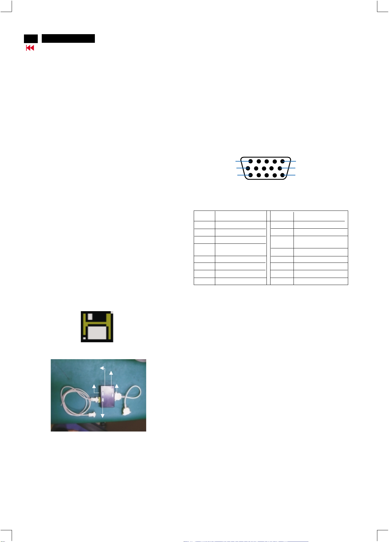
3. EDID301.EXE program (3138 106 10103) shown as Fig. 1
4. Software DDC Alignment kits (4822 310 11184) shown as Fig. 2.
The kit contents: a. Alignment box x1
Note: The EDID301.EXE (Release Version 1.58, 20000818)is a
windows-based program, which cannot be run in MS-DOS.
b. Printer cable x1
c. D-Sub cable x1
3. Pin assignment
A. 15-pin D-Sub Connector
The 15-pin D-sub connector (male) of the signal cable
on the 3rd row for DDC feature :
1
6
11
Pin No.
1
2
3
4
5
6
7
8
Assignment
Red video input
Green video input
Blue video input
Ground
for selftest(PC ground)
Red video ground
Green video ground
Blue video ground
Pin No.
9
10
11
12
13
14
15
DDC 5V
Sync. Ground
Ground
Bi-directional data(SDA)
H.Sync
V.Sync(VCLK)
Data clock line(SCL)
5
10
15
Assignment
Figure 1
Diskette with EDID301.EXE
DC 8V~12V
To Monitor
Fig. 2 Alignment Kits
EDID301.EXE
Ver:1.58
Video CardVideo Card
Power
To Printer
indicator
Page 23
DDC Instructions (Continued)
http://jdwxzlw.5d6d.com/?fromuser=华盛维修
家电维修资料网,免费下载各种维修资料
V20 107E5
Go to cover page
23
X
4. Configuration and procedure
There is no Hardware DDC (DDC IC) anymore. Main EEPROM stores
all factory settings and DDC data (EDID code) which is so called
Software DDC. The following section describes the connection and
procedure for Software DDC application. The main EEPROM can be reprobrammed by enabling "factory memory data write" function on the
DDC program (EDID301.EXE).
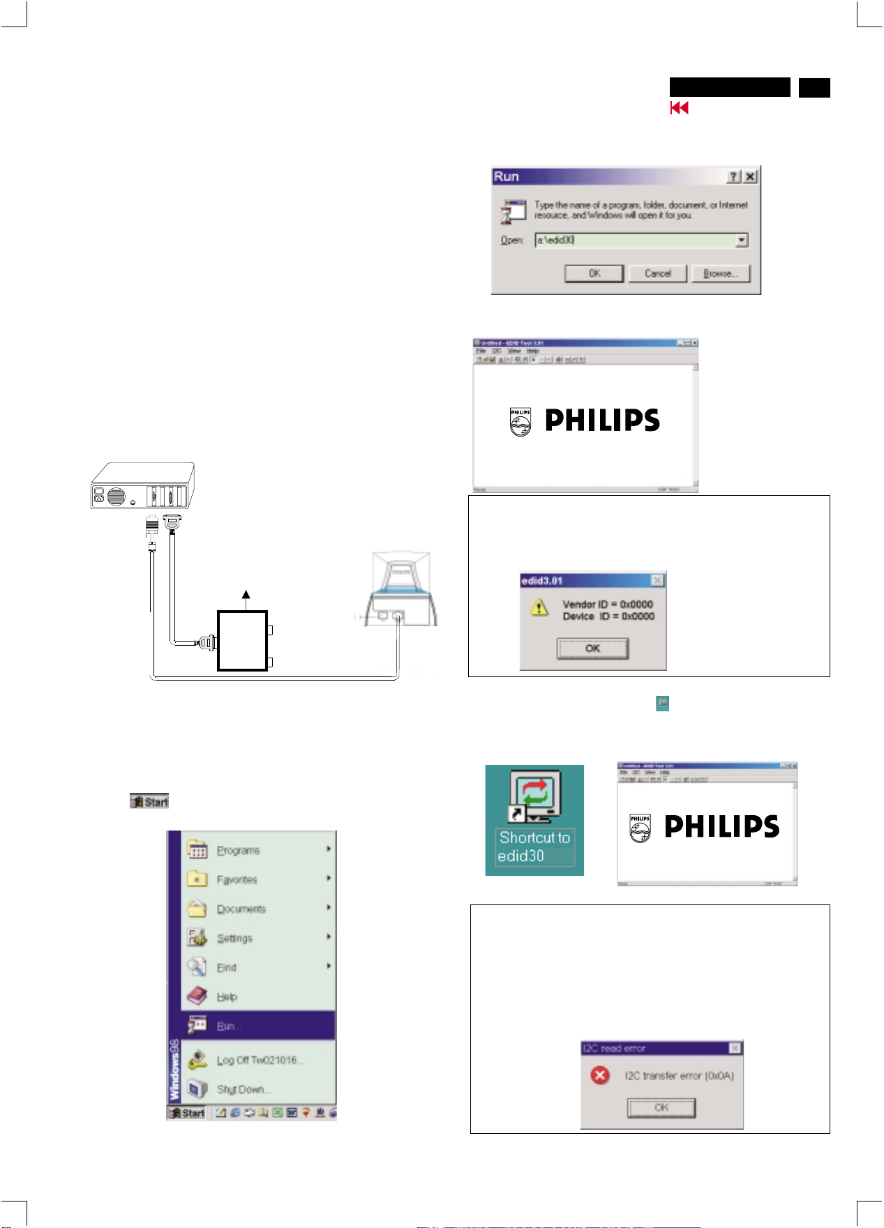
*** INITIALIZE ALIGNMENT BOX ***
In order to avoid that monitor entering power saving mode due to
sync will cut off by alignment box, it is necessary to initialize
alignment box before re-programming DDC Data. Following steps
show you the procedures and connection.
Step 1
: Supply 8~12V DC power source to the Alignment box by
plugging a DC power cord or using batteries.
Step 2
: Connecting printer cable and video cable of monitor as
shown in Fig.3.
PC
Fig. 3
Rear view of the monitor
DC Power
8~12 V
~
~
3. At the submenu, type the letter of your computer's floppy disk drive
followed by :EDID301 (for example, A:\EDID301, as shown in Fig. 5).
Fig. 5
4. Click button. The main menu appears (as shown in Fig. 6).OK
This is for initialize alignment box.
Fig. 6
Note 1: If the connection is improper, you will see the following error
message (as shown in Fig. 7) before entering the main menu.
Meanwhile, the (read EDID) function will be disable. At this time,
please make sure all cables are connected correctly and fixedly,
and the procedure has been performed properly.
To video card
Step 3: Installation of EDID301.EXE
Method 1: Start on DDC program
Start Microsoft Windows.
1. Insert the disk containing EDID301.EXE program into floppy disk
drive.
2. Click , choose Run at start menu of Windows 95/98 as
shown in Fig. 4.
To printer port (LTP1)
Printer
Port
To
Monitor
To P C
Video cable
Fig. 4
Fig. 7
Method 2: After create a shortcut of EDID301.EXE
: Double click EDID301 icon (as shown in Fig. 8) which is
on the screen of Windows Wallpaper.
Bring up main menu of EDID301 as shown in Fig. 9.
This is for initialize alignment box.
1
Fig. 8
Note 2: During the loading, EDID301 will verify the EDID data which just
loaded from monitor before proceed any further function, once
the data structure of EDID can not be recognized, the following
error message will appear on the screen as below. Please
confirm following steps to avoid this message.
1. The data structure of EDID was incorrect.
2. DDC IC that you are trying to load data is empty.
3. Wrong communication channel has set at configuration setup
windows.
4. Cables loosed or poor contact of connection.
Fig. 9
Page 24
24
http://jdwxzlw.5d6d.com/?fromuser=华盛维修
家电维修资料网,免费下载各种维修资料
V20 107E5
Go to cover page
DDC Instructions (Continued)
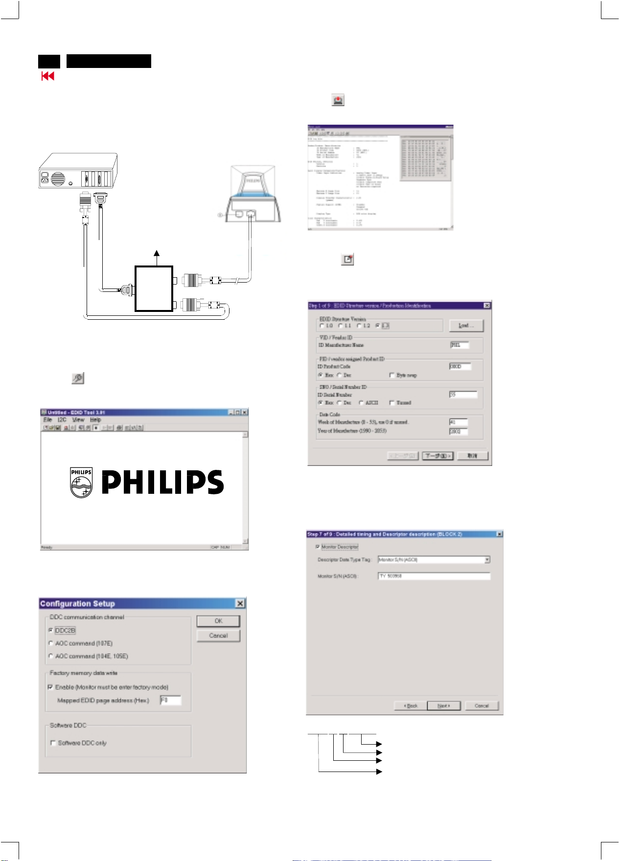
Re-programming EEPROM (Software DDC)
Step 1: After initialize alignment box, connecting all cables and
box as shown in Fig. 10
PC
Rear view of the monitor
Fig. 10
DC Power
8~12 V
~
~
To video card
Step 2: Read DDC data from monitor
1-1 Click the left key of Mouse, or hit any key on the keyboard,
then the characters disappear from the screen.
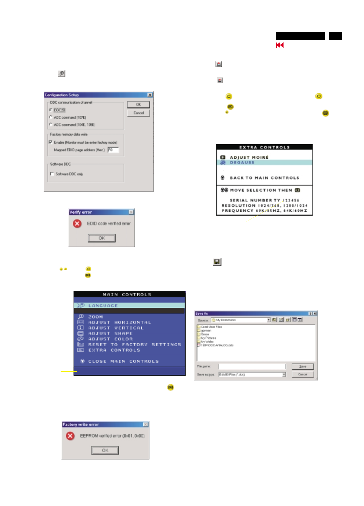
1-2 Click icon as shown if Fig. 11 from the tool bar to bring up
the "Configuration Setup" windows as shown in Fig. 12.
To printer port (LTP1)
Printer
Port
To
Monitor
To PC
Video cable
4. Click icon (Read EDID function) to read DDC EDID data from
monitor. The EDID codes will display on screen as shown in Fig. 13.
Fig. 13
Step 3: Modify DDC data (verify EDID version, week, year)
1. Click (new function) icon from the tool bar, bring up
Step 1 of 9 as shown in Fig. 14 .
EDID301 DDC application provides the function selection and
text change (select & fill out) from Step 1 to Step 9.
Fig. 14
2. Select the DDC2B as the communication channel.
Select " " & fill out " " for Mapped EDID page address
Enable F0
as shown in Fig. 12.
3. Click OK button to confirm your selection.
Fig. 11
Fig. 12
Step 4: Modify DDC data (Monitor Serial No.)
1. Click till the Step 7 of 9 window appears as shown in Fig. 15.
2. Fill out the new Serial No. (for example, TY 503960, TY 123456).
3. Click till the last step window appears, then click to exit
Definition of Serial Number (barcode format)
TY00 02 41000001
Next
Next Finish
the Step window.
------>
two space
(for example: change it from TY 503960
to TY 123456)
Serial Number (U.S.A: 8 digit)
(Others regions: 6 digit)
Week
Year
TY Code
TY----Chungli
CX----Dong Guan
HD----Hungary
BZ----Suzhou
Fig. 15
Page 25
DDC Instructions (Continued)
http://jdwxzlw.5d6d.com/?fromuser=华盛维修
家电维修资料网,免费下载各种维修资料
V20 107E5
Go to cover page
25
Step 5: **Configuration Setup & Enter Factory Mode **
for "write EDID data"
1. Click icon from the tool bar to bring up the Configuration Setup
windows again. Then, select "Software DDC only" as shown in
Fig. 16. Click "OK".
Fig. 16
If you do not select "Software DDC only", when you execute
"write EDID", it will bring up an error message as below.
Step 6: Write DDC data
1. Click (Write EDID) icon from the tool bar to write DDC data.
Bring up "Writing 0%~100%, ready" a progressing bar on the left
down corner.
2. Click (Read EDID) to confirm it.
Step 7: Confirm Serial Number in User Mode
1. Press the button to turn off the monitor. Press the button
again to turn on the monitor.
2. Press the button to bring up the OSD Main Menu.
3. Press the button to select Extra Controls, press the
button to confirm your selection.
4. Confirm the Serial Number "123456" is updated
as shown in Fig. 18.
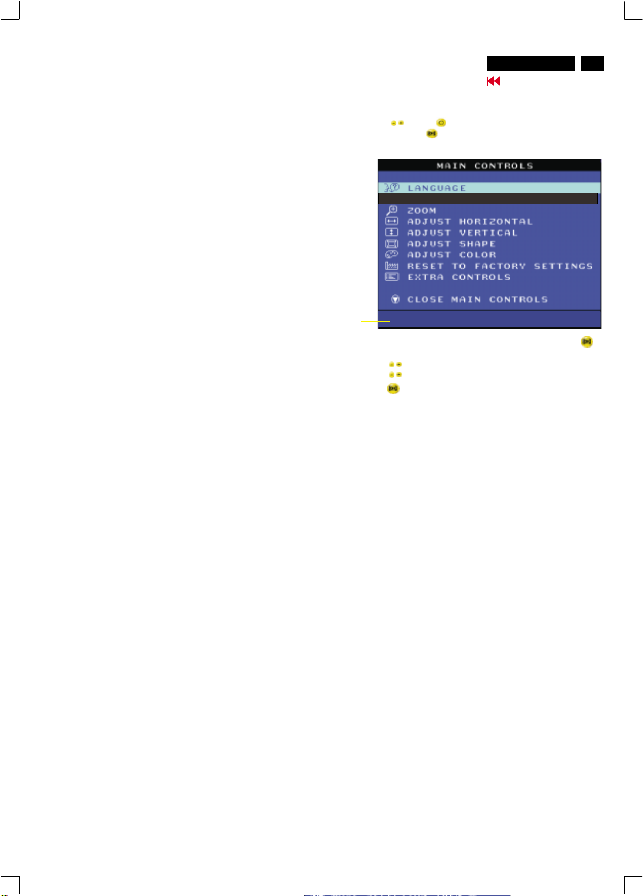
To access factory mode
1. Turn off monitor (don't turn off PC)
2. Press " " and " " simultaneously on the front control
panel,then press " ",wait till the OSD menu with characters
V20 107E5 V0.20 20021217 (below OSD menu)" come on the
screen of monitor.
Fig. 17
MODEL SELECT
Factory
Mode
Indicator
If OSD menu disappears on the screen of monitor, press " "
again (anytime), then the OSD menu comes on the screen again.
V20 107E5 V0.20 20021217
Fig. 18
Step 8: Save DDC data
Sometimes, you may need to save DDC data as a text file for using
in other IC chip. To save DDC data, follow the steps below:
1. Click (Save) icon (or click "file"-> "save as") from the tool bar
and give a file name as shown in Fig. 19.
The file type is EDID301 file (*.ddc) which can be open in WordPad.
By using WordPad, the texts of DDC data & table (128 bytes, hex
code) can be modified. If DDC TEXTS & HEX Table are completely
correct, it can be saved as .ddc flie to re-load it into EEPROM for
DDC Data application.
Fig. 19
107E5 V20
2. Click .Save
If you do not access "Factory mode", when you execute
"write EDID", it will bring up an error message as below.
Page 26
26
http://jdwxzlw.5d6d.com/?fromuser=华盛维修
家电维修资料网,免费下载各种维修资料
V20 107E5
Go to cover page
DDC Instructions (Continued)
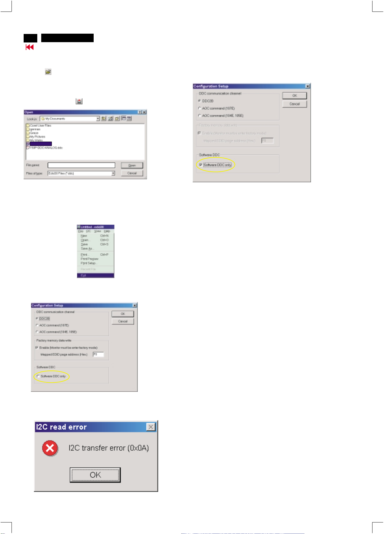
Step 9: Load DDC data
1. Click from the tool bar.
2. Select the file you want to open as shown in Fig. 20.
3. Click .
4. Access "Factory Mode" and enable "Software DDC only" as shown
5. Write EDID (click ).
Step 10: Exit DDC program
Pull down the File menu and select Exit as shown in Fig. 21.
(EDID Tool 3.01)
Open
in Fig. 17 & Fig. 16.
107E5 V20.DDC
107E5 V20.DDC
Fig. 20
Note2:InFactory Mode: Read/Write DDC data
Before Read/Write EDID code, please confirm that the
Software DDC only was enabled
as shown in Fig. 23.
Fig. 23
Fig. 21
Note1 : In User Mode: Read DDC data only
If you do not disable "Software DDC only", when you execute
"read EDID", it will bring up an error message as below.
Before read EDID code, please confirm that the
DDC only was disabled
as shown in Fig. 22.
Software
Fig. 22
Page 27
Electrical Adjustments
http://jdwxzlw.5d6d.com/?fromuser=华盛维修
家电维修资料网,免费下载各种维修资料
V20 107E5
Go to cover page
27
0. General
8 factory-preset modes1. This monitor has as below.
720 x 400 31.5 kHz/70 Hz
640 x 480 31.5 kHz/60 Hz
640 x 480 43.3 kHz/85 Hz
800 x 600 46.9 kHz/75 Hz
800 x 600 53.6 kHz/85 Hz
1280 x 960 60.0 kHz/60 Hz
1024 x 768 68.7 kHz/85 Hz
1280 x 1024 64.0kHz/60Hz
1.1 14
factory-preload modes as below
640 x 350 31.5 kHz/70 Hz
640 x 350 37.9 kHz/85 Hz
640 x 480 37.5 kHz/75 Hz
640 x 480 37.9 kHz/72.8 Hz
640 x 480 50.6 kHz/100 Hz
720 x 400 37.9 kHz/85 Hz
800 x 600 37.90kHz/60Hz
800 x 600 48.1 kHz/72 Hz
800 x 600 63.9 kHz/100 Hz
832 x 624 49.7 kHz/75 Hz
1024 x 768 48.4 kHz/60 Hz
1024 x 768 56.5 kHz/70 Hz
1152 x 864 67.5 kHz/75 Hz
1024x768 60.0 kHz/75 Hz
2. AC/DC Measurement:
The measurements for AC waveform and DC figure is based on 640 x
480 31.5 kHz/60 Hz resolution mode with test pattern "gray scale".
Power input: 110V AC
5. To access factory mode
5.1 Turn off monitor (don't turn off PC)
5.2 Press '" " and " " simultaneously on the front control
panel,then press " ",wait till the OSD menu with characters
M32 107E/T4P V1.23 20020426 (below OSD menu)" come on the
screen of monitor.
Factory
Mode
Indicator
5.3 If OSD menu disappears on the screen of monitor, press " "
again (anytime), then the OSD menu comes on the screen again.
5.4 Using " " : to select OSD menu.
5.5 Using " " : to increase or decrease the setting.
5.6 Using " " to access/confirm the selection.
To leave factory mode
5.7 After alignment of factory mode, turn off monitor (if you do not
turn off monitor, the OSD menu is always at the factory mode),
then turn on monitor again (at this moment, the OSD menu goes
back to user mode).
MODEL SELECT
V20 107E5 V0.20 20021217
3.Monitor the following auxiliary voltages.
+5V source across 7153 Pin out and GND +5V +/- 0.25 VDC
+6.1V source across C2154 +6.1V +/- 0.3 VDC
+12V source across C2155 +12.9V +/- 1.0 VDC
-12V source across C2156 -12.7V +/- 1.0 VDC
+50V source across C2152 +50V +/- 1.0 VDC
-190V source across C2630 -173V +/- 10.0 VDC
+83V source across C2153(+toGnd) +76V +/- 2.0 VDC
4. General conditions for alignment
4.1 During all alignments, supply a distortion free AC mains voltage
to set via an isolating transformer with low internal impedance.
4.2 Align in pre-warmed condition, at least 30 minutes warm-up with
nominal picture brightness.
4.3 Purity, geometry and subsequent alignments should be carried
out in magnetic cage with correct magnetic field.
Northern hemisphere : H=0, V=450 mG, Z=0
Southern hemisphere : H=0, V=-500 mG, Z=0
Equatorial Support : H=0, V=0 mG, Z=0
4.4 All voltages are to be measured or applied with respect to ground.
Note: Do not use heatsink as ground.
4.5 Adjust brightness controls to center position except for contrast
control which should be set to MAX.
6. Picture geometry setting
- Apply a video signal with cross-hatch pattern.
- Apply a video signal in the 1024 x 768 with 68.7 kHz/85 Hz mode.
- Set contrast control at Max. position, and brightness control in the
mid-point.
6.4 Alignment of horizontal geometry and vertical geometry
6.4.1 Adjust the H-width to 306 mm
6.4.2 Adjust the H-phase to center position.
6.4.3 Adjust V-size to 230mm.
6.4.4 Adjust V-Position to center.
Adjust/Trapezoid/pincushion/balance pincushion/paralleogram
6.4.5 Adjust picture tilt via I C BUS for correct top/bottom lines.
6.4.6 Adjust the top and bottom corner by I C to get optimum
corner geometry.
6.4.7 Adjust the parallelogram by I CBUS to get optimum vertical line.
6.4.8 Adjust the balance pincushion by I C BUS to get optimum
vertical line.
6.4.9 Adjust the trapezoid to get optimum vertical line.
6.5 Adjust size/centering/trapezium/pincushion/parallelogram
of all other preset modes via I C bus.
(to repeat from step 6.4.1 to step 6.4.9)
2
2
2
2
2
Page 28
28
http://jdwxzlw.5d6d.com/?fromuser=华盛维修
家电维修资料网,免费下载各种维修资料
9
V20 107E5
Go to cover page
Electrical Adjustments (Continued)
7. Alignment of Vg2 cut-off point, white tracking
Equipment : 1. Video Test Generator-801GC (Quantum Data)
VG2 [(screen), at the bottom of the L.O.T.].
7.1 Apply a video signal in the 1024 x 768 with 68.7 kHz/85 Hz mode,
select the "full white pattern" (sizes 306 x 230 mm).
* Use color-analyzer (Minolta CA-100) to adjust R/G/B cutoff and
gain.
OSD R/G/B cut-off and R/G/B gain can be accessed (for Philips
CRT), with initial data:
9300 K
R cutoff = 50%, R gain = 73% (I C)
G cutoff = 50%, G gain = 73% (I C)
B cutoff = 50%, B gain = 73% (I C)
6500 K
R cutoff = 50%, R gain = 71% (I C)
G cutoff = 50%, G gain = 71% (I C)
B cutoff = 50%, B gain = 71% (I C)
Brightness = 50%, Sub-Contrast = 86%, ABL = 63% (I C)
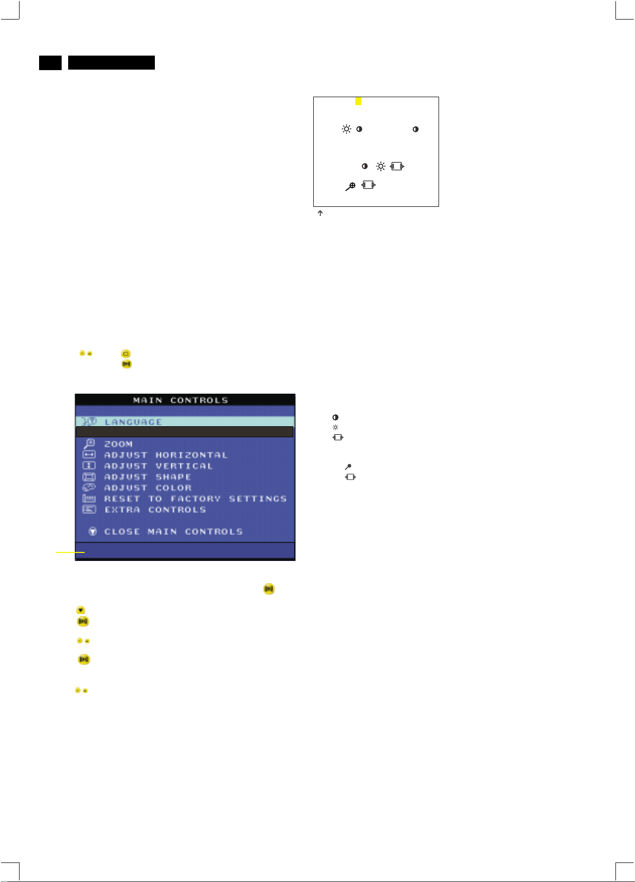
Step 1: To access factory mode
- Turn off monitor (don't turn off PC)
- Press " " and " " simultaneously on the front control
panel,then press " ",wait till the OSD menu with characters
V20 107E5 V0.20 20021217 (below OSD menu)" comes on the
screen of monitor as shown in Fig. 2.1.
2. Color-analyzer (Minolta CA-100)
o
2
2
2
o
2
2
2
2
9300 BIAS R G B GAINRGB
6500 BIAS R G B GAINRGB
SRGB BIAS R G B GAINRGB
SRGB ( ) OSD
V (OFF GAIN LINBAL FOCUS)
CORNER(T B) EHT ( H V )
PINCOR(T B S W) B+
ABL SUB ( )
LIN ( H V)
RANGE ( )
EXIT
152
(for example: 152 is value of "BIAS R")
BIASRGB:R(red) G(green) B(blue) cutoff
GAINRGB:R(red) G(green) B(blue) gain
OSD contrast : OSD window contrast
V OFFSET : Vertical raster center
V GAIN : Vertical size center
VLIN BAL : Vertical Linearity Balance
V FOCUS : Vertical Focus adiustment
T CORNER: Corner Correctionof TOP
B CORNER: Corner Correctionof BOTTOM
EHT H : Horizontal Size compensation
EHT V : Vertical Size compensation
Pincor T : Top corner asymmetry correction
Pincor B :Bottom corner asymmetry correction
Pincor S : Pincushion S-correction
Pincor W : Pincushion W-correction
B+ : High voltage adjustment
ABL : Auto brightness Limitation
SUB : Sub Contrast allowance range
SUB : Sub Brigntness allowance range
SUB : Horizontal size range adjustment range
HLIN : Horizontal Linearity
V LIN : Vertical Linearity
RANGE : Zoom range
RANGE : User Horizontal size adjustment range
(for ref. 164,173,133,216,188,194)
(for ref. 158,177,136,208,148,132)
(for ref. 161,178,137,182,132,118)
(for ref. 127,255,190)
(for ref. 127,255,140,140)
(for ref. 188,190,83,105)
(for ref. 112,124,125,236,124)
(for ref. 129,220,100,194)
(for ref. 88,34)
(for ref. 127,255)
Fig. 2.2
Factory
Mode
Indicator
- If OSD menu disappears on the screen of monitor, press " "
again (anytime), then the OSD menu comes on the screen again.
- Using " " to select .
- Press " " button to access/confirm the selection.
Bring up the "function adjustment" as shown in Fig. 2.2.
- Press '" " button for function selection as shown in
Fig. 2.2.
- Press " " button to access/confirm each item selection
(The cursor indicator will be changed from yellow colour to
red colour.)
- Using " " : to increase or decrease the value.
MODEL SELECT
V20 107E5 V0.20 20021217
Fig. 2.1
M 32 107E/T4P V1.23 20020426
7.2 Connect the video input, set brightness control at center, and
contrast control at maximum
7.3
set R,G,B cut-off at 127 9300k and 6500K(EEPROM preload value)
R,G,B gain at 185 9300k and
180 6500K(EEPROM preload value)
ABL at 160 9300k (EEPROM preload value)
SUB-CON at 220 9300k (EEPROM preload value)
7.4 Adjust 9300K color:
With color analyzer CA 100,
set R,G,B cut-off x=0.283, y=0.297, Y=0.10
7.5 Set R,G,B gain Y= 41+/- 1FL, x=0.283, y=0.297
7.6 Repeat 7.4,7.5 until RGB three guns get x=0.283, y=0.297,
readings on low Y=0.10+/-0.05FL and high Y=41+/-1FL
brightness of 9300.
7.7 Adjust 6500K color:
With color analyzer CA 100,
set R,G,B cut-off x=0.313, y=0.329, Y=0.10
7.8 Set R,G,B gain Y= 36+/- 1FL, x=0.313, y=0.329
7.9 Repeat 7.7,7.8 until RGB three guns get x=0.313, y=0.329,
readings on low Y=0.10+/-0.05FL and high Y=36+/-1FL
brightness of 6500.
7.10 Adjust SUB-CON to get Y=41+/-1FL.
7.11 Apply full white pattern of 9300 mode, adjust ABL to reach
30 +/- 1FL(at 9300 high brightness of R/G/B gain,
contrast at 100%)
Page 29
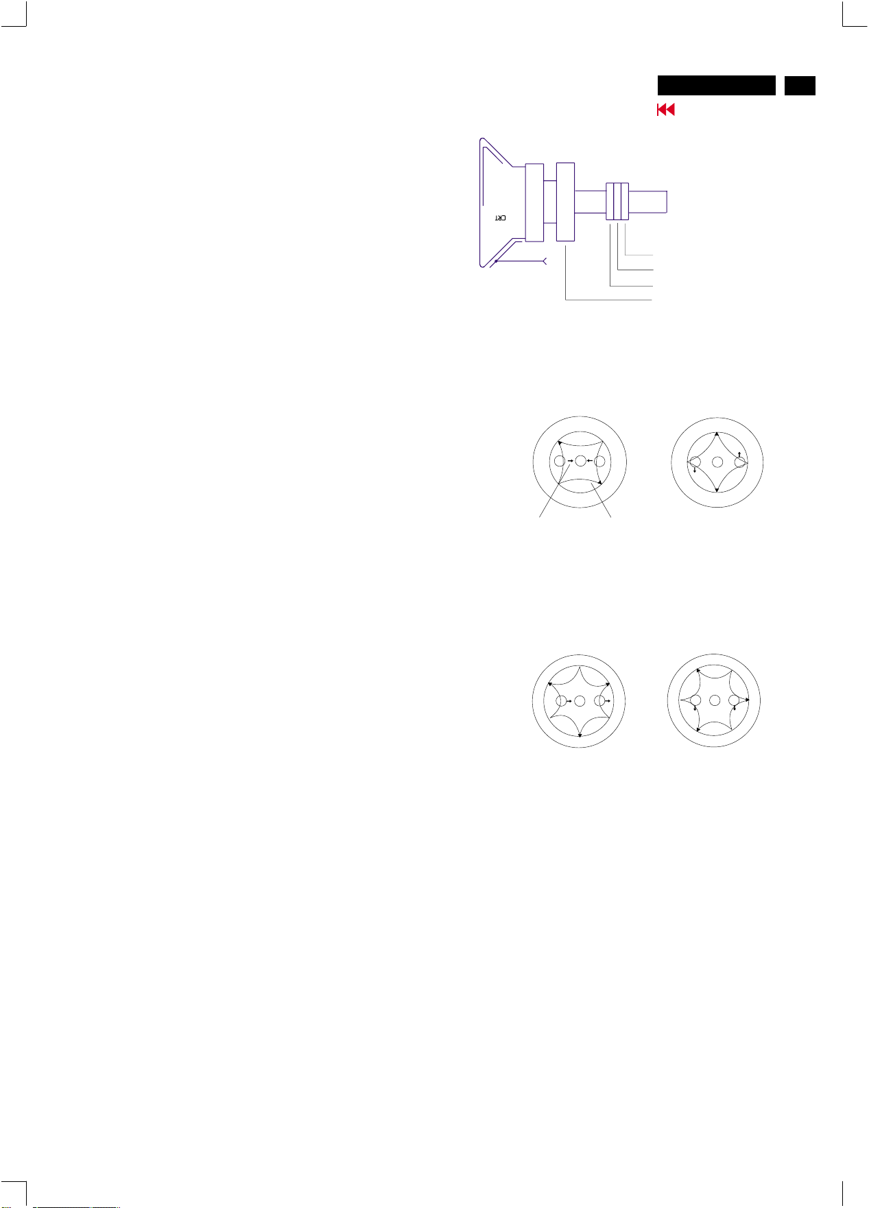
Electrical Adjustments (Continued)
http://jdwxzlw.5d6d.com/?fromuser=华盛维修
家电维修资料网,免费下载各种维修资料
8. Focus adjustment
Apply a signal of " ME " pattern. at 68.7 kHz/85 Hz mode set the
brightness to mid-position , contrast to max - position and adjust
the focus for optimal sharpness in the area within 2/3 from the
screen center.
9. Loading DDC code
The DDC HEX data should be written into the EEPROM
(7802) by EDID301.EXE Program(3138 106 10103)
and software DDC Alignment kits (4822 310 11184).
10. Purity adjustment
- Make sure the monitor is not exposed to any
external magnetic field.
- Produce a full red pattern on the screen, adjust the
purity magnet rings on the PCM assy (on CRT) to
obtain a complete field of the color red. This is done
by moving the two tabs (2-pole) in such a manner
that they advance in an opposite direction but at
the same time to obtain the same angle between
the two tabs, which should be approximately 180
degree.
- Check by full green pattern and full blue pattern
again to observe their respective color purity.
V20 107E5
Go to cover page
2-pole purity magnet
6-pole convergence magnet
4-pole convergence magnet
Deflection Yoke
4-pole Beam motion producced by the
4-pole convergence magnet
S
B
N
N
G
R
S
S
N
B
G R
N
S
29
11. Static convergence
Introduction
Slight deviation in the static convergence can be
corrected by using two permanent pairs of magnets
which are fitted around the neck of the CRT. These
are the 4-pole magnet and the 6-pole magnet.
The 4-pole magnet move the outermost electron
beams (R and B) parallel in the opposite direction
from the other. The 6-pole magnet moves the
outermost electron beam (R, B and G) parallel in the
opposite direction from the other.
The magnetic field of the above magnets do not affect
the center of the CRT neck.
Setting
- Before the static convergence setting can be made,
the monitor must be switched on for 30 minutes.
- The focus setting must be made correctly.
- Signal: 640 * 480, 31.5 kHz/60 Hz mode.
- Set the tabs of the 4-pole magnet in the neutral
position. This is when the tabs are opposite one
another. In this position the magnets do not affect the
deflection of the R and B electron beams.
- Set the tabs of the 6-pole magnet in the neutral
position. This is when the tabs are opposite one
another. In this position the magnets do not affect the
deflection of the R, B, and G electron beams.
- First set the 4-pole magnet optimally.
- Then set the 6-pole magnet optimally.
- If the convergence is not now optimal, then adjust to
the optimal setting with the 4-pole magnet and then with
the 6- Pole magnet again.
- Set the tabs of the 6-pole magnet in the neutral
position. This is when the tabs are opposite one
another. In this position the magnets do not affect the
deflection of the R, B, and G electron beams.
- First set the 4-pole magnet optimally.
- Then set the 6-pole magnet optimally.
- If the convergence is not now optimal, then adjust to
the optimal setting with the 4-pole magnet and then
with the 6- pole magnet again.
Beam displacement
direction
6-pole
Beam motion producced by the
6- pole convergence magnet
N
S
B
G
N
S
Magnetic flux
lines
S
R
N
N
S
B
N
S
S
R
G
N
Page 30
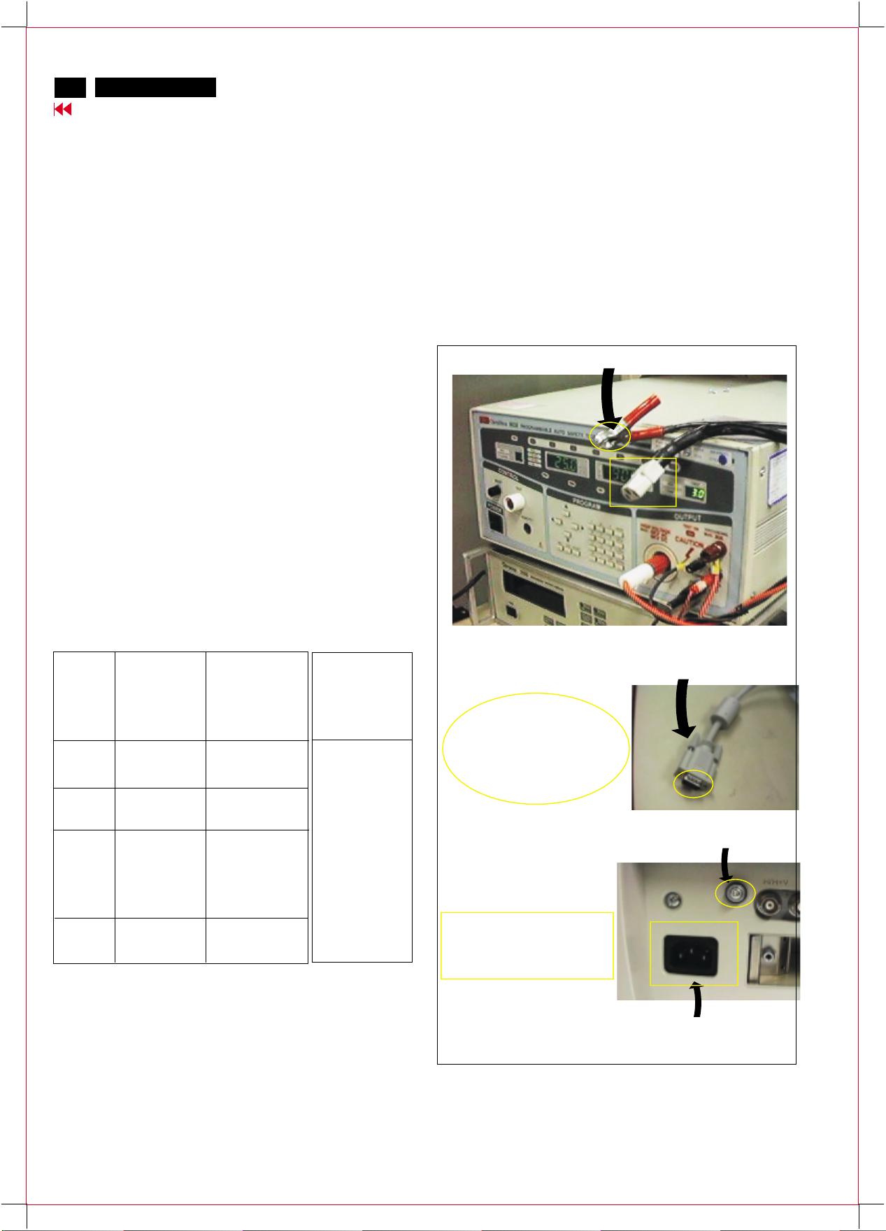
30
http://jdwxzlw.5d6d.com/?fromuser=华盛维修
家电维修资料网,免费下载各种维修资料
V20 107E5
Go to cover page
Safety test requirements
All units that are returned for service or repair must pass the
original manufactures safety tests. Safety testing requires both
and testing.Hipot Ground Continuity
HI-POT TEST INSTRUCTION
1. Application requirements
1.1 All mains operated products must pass the Hi-Pot test as
described in this instruction.
1.2 This test must be performed again after the covers have
been refitted following the repair, inspection or modification
of the product.
2. Test method
2.1 Connecting conditions
2.1.1 The test specified must be applied between the parallel-
blade plug of the mainscord and all accessible metal
parts of the product.
2.1.2 Before carrying out the test, reliable conductive
connections must be ensured and thereafter be
maintained throughout the test period.
3. Equipments and Connection
3.1. Equipments
For example :
- ChenHwa 9032 PROGRAMMABLE AUTO SAFETY
TESTER
- ChenHwa 510B Digital Grounding Continuity Tester
- ChenHwa 901 (AC Hi-pot test), 902 (AC, DC Hi-pot test)
Withstanding Tester
3.2. Connection
* Turn on the power switch of monitor before Hipot and
Ground Continuity testing.
Clip
Clip
2.1.3 The mains switch(es) must be in the "ON" position.
2.2 Test Requirements
All products should be HiPot and Ground Continuity tested as
follows:
Condition HiPot Test for HiPot Test for Ground Continuity
products where products where Test requirement
the mains input the mains input is
range is Full 110V AC(USA
range(or 220V type)
AC)
Test 2820VDC 1700VDC Test current:
voltage (2000VAC) (1200VAC) 25A,AC
Test time:
Test time 3 seconds 1 second 3 seconds(min.)
(min.) Resistance
required:
Trip set at 100 uA 5 mA <=0.09+R ohm,
current for Max. R is the
(Tester) limitation; set resistance of
at 0.1 uA for the mains cord.
Min. limitation
Ramp set at 2
time seconds
(ChenHwa 9032 tester)
Video cable
Connect the "video cable"
or "grounding screw"
to the CLIP on your tester.
Grounding screw
Connect the power cord
to the monitor.
2.2.1 The test with AC voltage is only for production purpose,
Service center shall use DC voltage.
2.2.2
The minimum test duration for Quality Control Inspector
must be 1 minute.No breakdown during the test.
2.2.3
The test voltage must be maintained within the specified
voltage + 5%.
2.2.4 The grounding blade or pin of mains plug must be
conducted with accessible metal parts.
4. Recording
Hipot and Ground Continuity testing records have to be kept for
a period of 10 years.
Power outlet
(Rear view of monitor)
Page 31
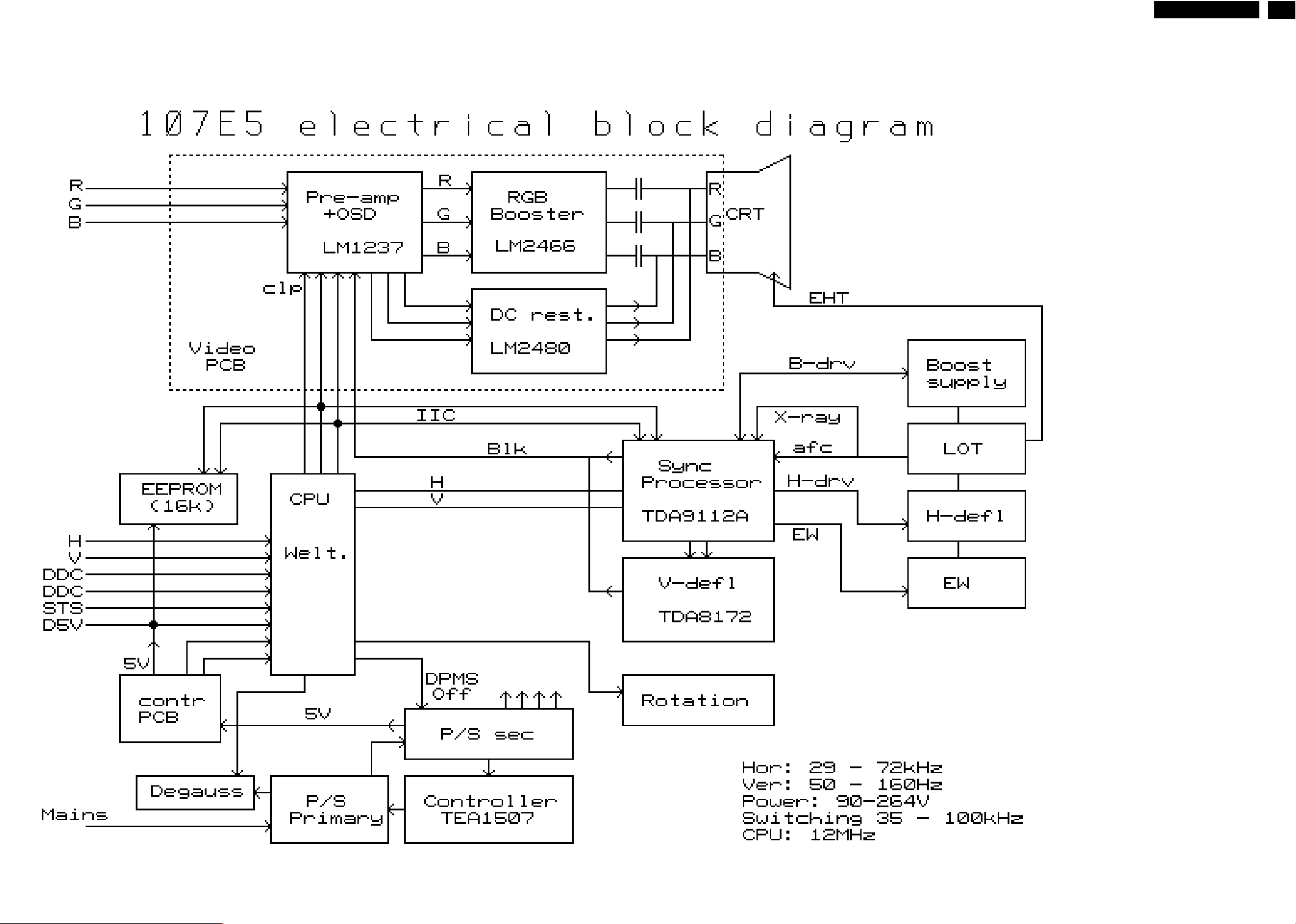
Block Diagram
http://jdwxzlw.5d6d.com/?fromuser=华盛维修
家电维修资料网,免费下载各种维修资料
V20 107E5
Go to cover page
9
31
Page 32
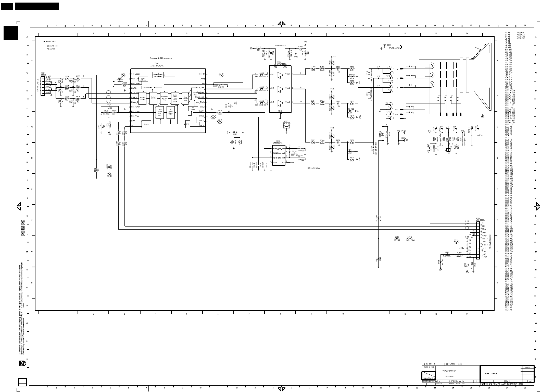
32
http://jdwxzlw.5d6d.com/?fromuser=华盛维修
家电维修资料网,免费下载各种维修资料
9
V20 107E5
Go to cover page
A
Video Panel Schematic diagram
0.9
1.4
1.2
1.7
A1
1.7
A2
A3
1.7
3.8
5
5
1.3
4.2
1.5
1.5
1.5
1.7
2
1.9
A4
A5
A6
47.8
53.7
49.3
54.8
54.3
55.1
5.9
-65.9
176.9
Page 33
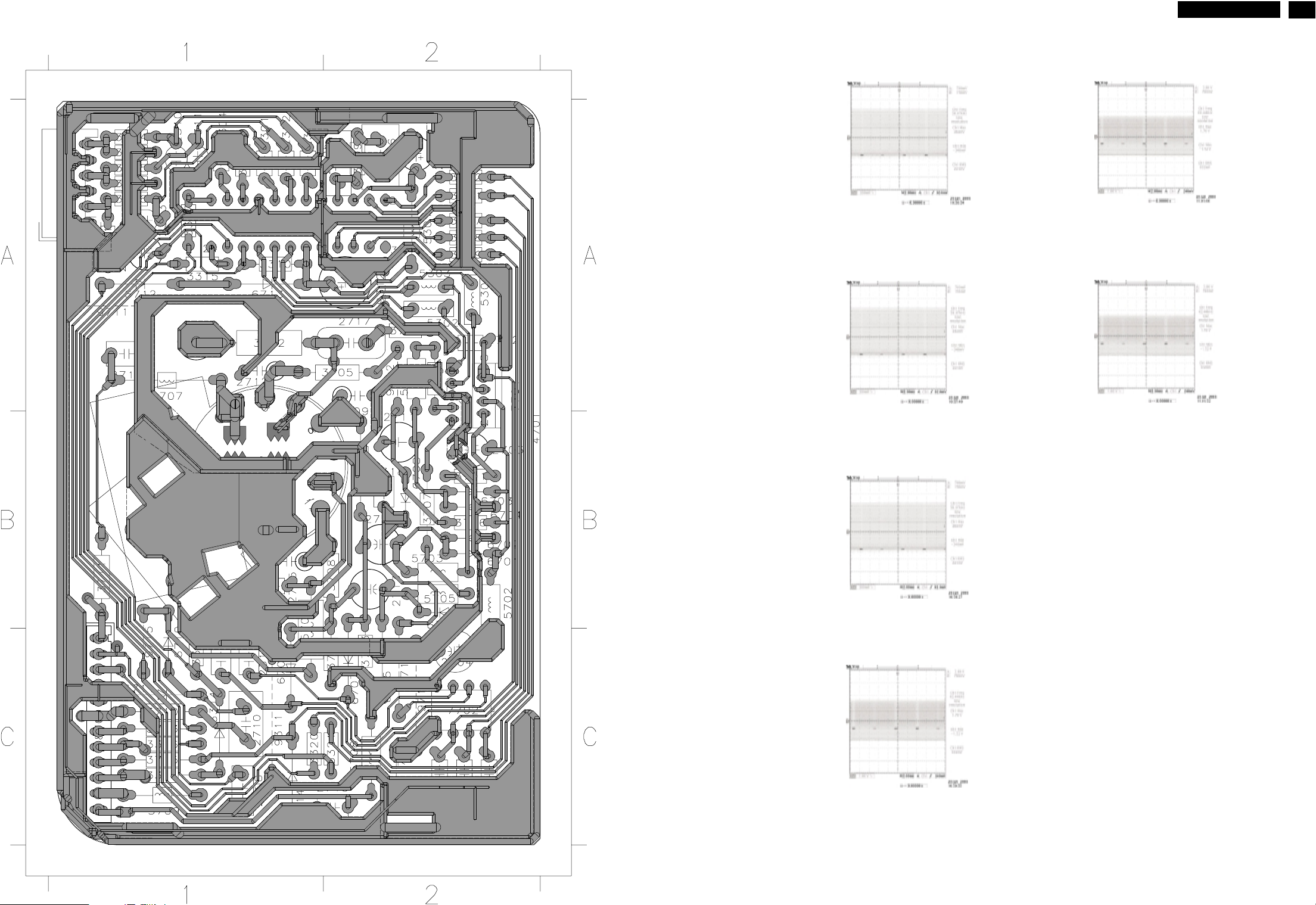
Video Panel C.B.A.(A)
http://jdwxzlw.5d6d.com/?fromuser=华盛维修
家电维修资料网,免费下载各种维修资料
V20 107E5
Go to cover page
9
33
GRID BOARD
REF LABEL SIDE
____ ___ ______
1301 A1 B
1703 B1 B
1711 B1 B
1712 A1 B
1715 B1 B
2301 A1 B
2302 A1 B
2303 A1 B
2304 A1 B
2305 A2 B
2306 A2 B
2307 A2 B
2308 C1 B
2309 A1 B
2310 A1 B
2311 A1 B
2312 A2 B
2313 A1 B
2314 C2 B
2315 C2 B
2316 C2 B
2317 B1 B
2318 B2 B
2319 C1 B
2702 A2 B
2703 B2 B
2704 C2 B
2708 B2 B
2709 A2 B
2710 C1 B
2711 B2 B
2712 A1 B
2713 B2 B
2714 B1 B
2715 B1 B
2716 A1 B
2717 A2 B
2718 C2 B
3301 A1 B
3302 A1 B
3303 A1 B
3304 A1 B
3305 A1 B
3306 A1 B
3307 A1 B
3308 A1 B
3309 A2 B
3310 A1 B
3311 A2 B
3312 A2 B
3313 C1 B
3314 C1 B
3315 A1 B
3316 C1 B
3317 A2 B
3318 A2 B
3319 A2 B
3320 C1 B
3321 C2 B
3701 B2 B
3702 B2 B
3703 C2 B
3704 A2 B
3705 A2 B
3706 B2 B
3707 B2 B
3708 B2 B
3709 C2 B
3710 C1 B
3711 B1 B
3712 A1 B
3713 C1 B
3714 A2 B
3715 C1 B
4701 B2 B
5301 A2 B
5302 A2 B
5303 A2 B
5304 A2 B
5702 B2 B
5703 B2 B
5704 A2 B
5705 B2 B
5706 B1 B
5707 A1 B
5708 C2 B
5709 C1 B
6314 C1 B
6701 B2 B
6702 B2 B
6703 B2 B
6704 B2 B
6705 C2 B
6706 B2 B
6707 C2 B
6708 B2 B
6709 C1 B
6710 C1 B
6711 C1 B
6712 A1 B
6713 A1 B
6714 C1 B
7301 A1 B
7701 A2 B
7702 C2 B
8701 C1 B
9311 C1 B
9312 A2 B
9711 A1 B
9712 A2 B
9714 C2 B
9715 C1 B
9716 C2 B
9717 C2 B
7301-5
7301-6
7301-7
7701-9
7701-7
7701-6
Page 34
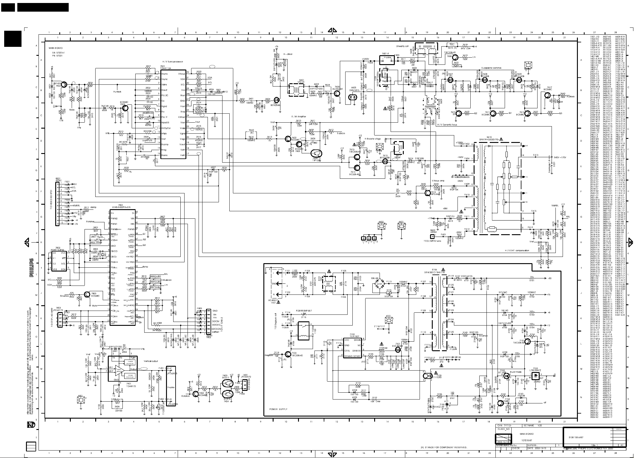
34
http://jdwxzlw.5d6d.com/?fromuser=华盛维修
家电维修资料网,免费下载各种维修资料
9
V20 107E5
Go to cover page
B
-2.7
Deflection- Main Panel Schematic diagram
3.8
B2
B3
B1
6.2
2.7
3.8
B10
5
5
5.1
B11
72.2
B9
4.2
26.9
B13
132.6
26.9
60.7
28
28
B16
28
28
3.4
B4
B5
7.8
2.8
4.7
4.9
4.6
38
2.1
2
5
25
2.8
B8
2.8
3.4
B7
5
1.8
3.7
3.7
B6
7.8
B12
2.3
27
5.3
5.3
B14
B15
50.4
131.6
1
B17
12.5
1.2
1.2
-12
B18
4.3
12.6
138.8
138.7
2.4
8.2
1.2
3.8
82.2
5.8
2.4
7.5
Page 35
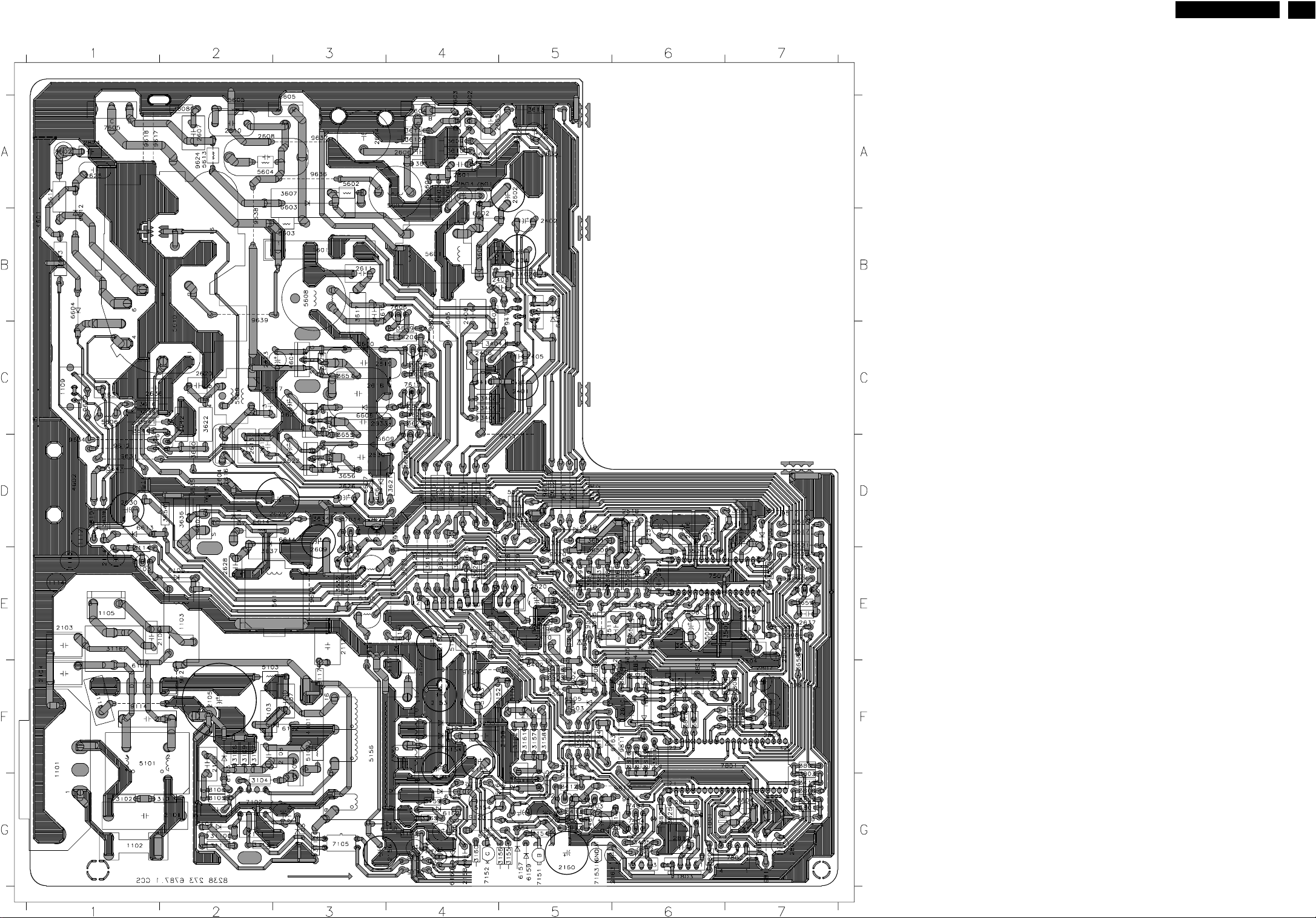
Main Panel C.B.A.(B)
http://jdwxzlw.5d6d.com/?fromuser=华盛维修
家电维修资料网,免费下载各种维修资料
V20 107E5
Go to cover page
9
35
Page 36
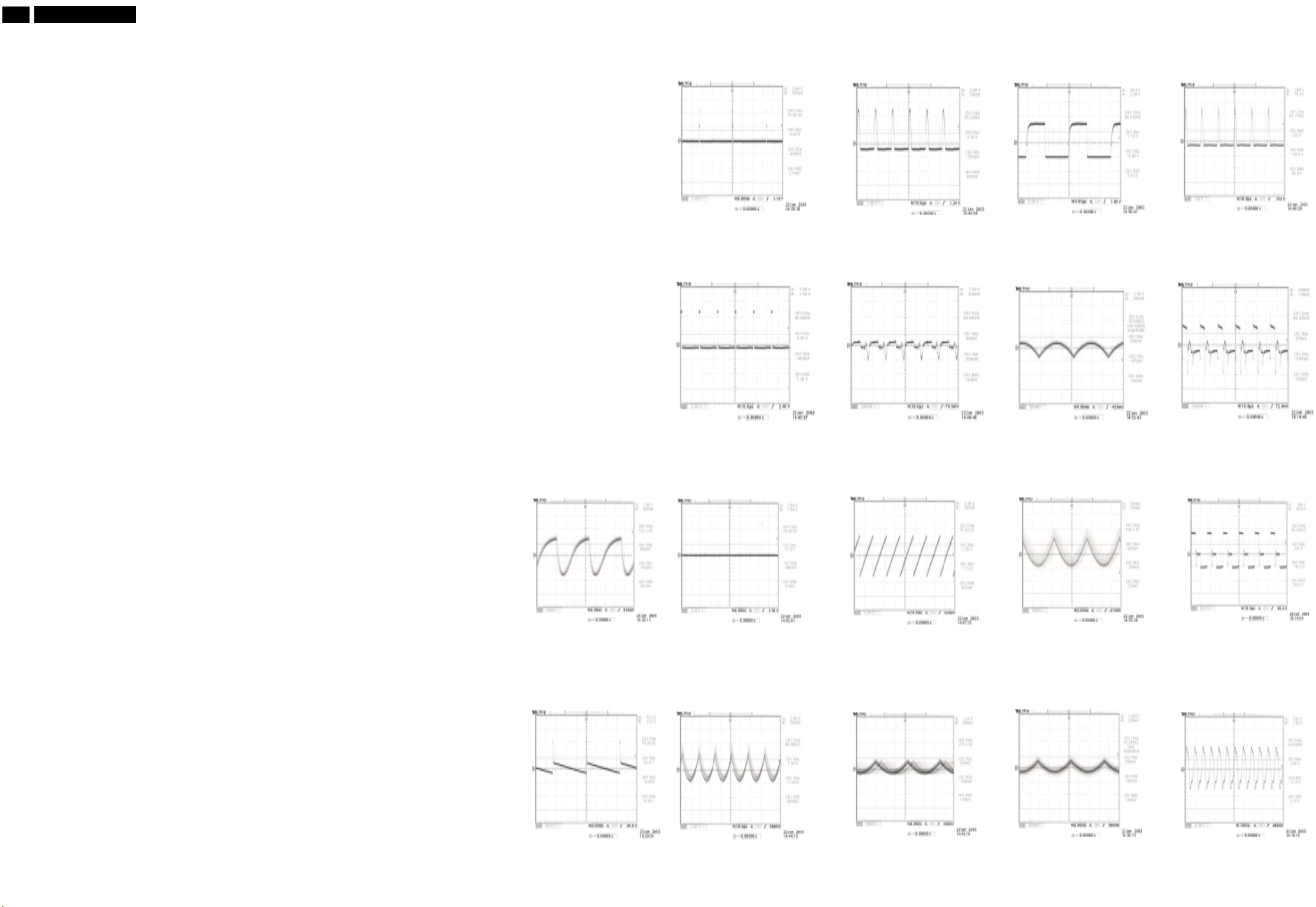
36
http://jdwxzlw.5d6d.com/?fromuser=华盛维修
家电维修资料网,免费下载各种维修资料
9
GRID BOARD
REF LABEL SIDE
B
V20 107E5
Go to cover page
____ ___ ____
1101 F1 B
1102 G1 B
1103 E2 B
1105 E1 B
1109 C1 B
1112 D 1 B
1113 E 1 B
1114 E 1 B
1401 G6 B
1601 B3 B
1801 G6 B
1802 F6 B
1803 G6 B
2101 G2 B
2103 E1 B
2104 F1 B
2105 F2 B
2106 E2 B
2107 F3 B
2108 F3 B
2109 F2 B
2110 G3 B
2111 G 2 B
2112 E3 B
2113 G2 B
2114 E1 B
2115 F2 B
2152 E4 B
2153 F4 B
2154 G4 B
2155 F4 B
2156 G4 B
2157 F5 B
2158 G4 B
2159 F5 B
2160 G5 B
2161 G5 B
2162 G4 B
2163 G6 B
2164 G5 B
2165 G5 B
2166 G4 B
2401 C5 B
2402 B5 B
2403 B5 B
2404 B5 B
2405 C5 B
2406 C4 B
2408 B4 B
2409 G5 B
2410 E5 B
2501 E7 B
2502 E7 B
2503 E7 B
2504 F7 B
2505 E6 B
2506 E6 B
2507 E6 B
2509 E6 B
2510 E6 B
2511 E5 B
2512 E6 B
2513 D7 B
2514 D7 B
2515 D6 B
2516 D6 B
2517 D6 B
2518 D6 B
2519 E5 B
2520 E5 B
2521 E6 B
2601 A4 B
2602 A5 B
2603 A4 B
2604 D2 B
2605 A4 B
2606 A4 B
2607 A2 B
2608 A2 B
2609 E3 B
2610 A2 B
2611 B3 B
2612 D2 B
2613 D2 B
2614 A3 B
2615 B3 B
2616 D2 B
2617 C3 B
2618 C3 B
2619 C3 B
2620 C2 B
2621 C3 B
2622 D3 B
2623 C2 B
2624 A1 B
2625 A1 B
2626 D3 B
2627 D3 B
2628 E2 B
2629 D3 B
2630 D1 B
2631 C1 B
2632 D3 B
2633 C3 B
2634 A5 B
2635 A4 B
2636 C1 B
2637 E7 B
2801 G7 B
2802 G7 B
2803 G7 B
2804 G7 B
2805 F6 B
2806 F6 B
2807 F7 B
2808 F7 B
2809 F7 B
2810 F6 B
2811 G6 B
2812 G6 B
3101 G2 B
3102 G1 B
3103 F2 B
3104 G2 B
3105 G2 B
3106 G2 B
3107 F2 B
3108 F2 B
3109 F2 B
3110 G2 B
3111 G 2 B
3112 G3 B
3113 G2 B
3114 E1 B
3115 F1 B
3116 E1 B
3117 F3 B
3152 F4 B
3153 F4 B
3154 G5 B
3155 G5 B
3156 G5 B
3157 F5 B
3158 F5 B
3159 G4 B
3160 G4 B
3161 F5 B
3162 F5 B
3163 G4 B
3164 F5 B
3165 G4 B
3401 D4 B
3402 B5 B
3403 B4 B
3404 C4 B
3405 G6 B
3406 C4 B
3407 B4 B
3408 C4 B
3409 C4 B
3410 C4 B
3411 G7 B
3412 G5 B
3413 G5 B
3414 G6 B
3415 D4 B
3416 F5 B
3501 F5 B
3502 E5 B
3503 E4 B
3504 F5 B
3505 F5 B
3506 F5 B
3507 E7 B
3508 E7 B
3509 E7 B
3510 E6 B
3511 E4 B
3512 E6 B
3513 E6 B
3514 E6 B
3515 E5 B
3516 E6 B
3517 E6 B
3518 E5 B
3519 E5 B
3520 E7 B
3521 D7 B
3522 E7 B
3523 D7 B
3524 E6 B
3525 E6 B
3526 E4 B
3601 D5 B
3602 D5 B
3603 A4 B
3604 A4 B
3605 B4 B
3606 B4 B
3607 A3 B
3608 A2 B
3609 A4 B
3610 A4 B
3611 A4 B
3612 E5 B
3613 A5 B
3614 A4 B
3615 A4 B
3616 C1 B
3617 B3 B
3618 E4 B
3619 C4 B
3620 C4 B
3621 D4 B
3622 C2 B
3623 C3 B
3624 C4 B
3625 C4 B
3626 D3 B
3627 C4 B
3628 D4 B
3629 C3 B
3630 C4 B
3631 C4 B
3632 E3 B
3633 E3 B
3634 D3 B
3635 D2 B
3636 D2 B
3637 E2 B
3638 C1 B
3639 D1 B
3640 D2 B
3641 C1 B
3642 C2 B
3643 B1 B
3644 C1 B
3645 E5 B
3646 E4 B
3647 D1 B
3648 E5 B
3649 E5 B
3650 E5 B
3651 D5 B
3652 E5 B
3653 E5 B
3654 D2 B
3655 D3 B
3656 D3 B
3657 C3 B
3658 F7 B
3659 E7 B
3660 E7 B
3801 G7 B
3802 G7 B
3803 G7 B
3804 G6 B
3805 F7 B
3806 G7 B
3807 F7 B
3808 F7 B
3809 F7 B
3810 F7 B
3811 F7 B
3812 F6 B
3813 F6 B
3814 F6 B
3816 F6 B
3817 F6 B
3818 F6 B
3819 G6 B
3820 G6 B
3821 G5 B
3822 G5 B
3823 F6 B
3824 F6 B
3825 G6 B
4101 F3 B
4401 B5 B
4601 B1 B
4602 D1 B
4603 D2 B
4604 C3 B
5101 F1 B
5102 F3 B
5103 F2 B
5151 E3 B
5152 E4 B
5153 F4 B
5154 G4 B
5155 E3 B
5156 F3 B
5157 F4 B
5501 D5 B
5601 B4 B
5602 A3 B
5603 B3 B
5604 A2 B
5605 A2 B
5606 C1 B
5607 A4 B
5608 B3 B
5609 C2 B
5610 C2 B
5611 E3 B
5612 A1 B
5613 A2 B
5614 D2 B
5615 D4 B
5616 D5 B
6101 F1 B
6102 F3 B
6103 G2 B
6104 G2 B
6105 G3 B
6106 E2 B
6151 E4 B
6152 F4 B
6153 F4 B
6154 F4 B
6155 G4 B
6156 G4 B
6157 G5 B
6158 G4 B
6159 G5 B
6160 G4 B
6161 G4 B
6162 G4 B
6163 F6 B
6401 B5 B
6402 F5 B
6501 E5 B
6502 F6 B
6503 F5 B
6504 F5 B
6505 F5 B
6506 D7 B
6507 E6 B
6508 E5 B
6509 E6 B
6510 D5 B
6601 A4 B
6602 B4 B
6603 A3 B
6604 B1 B
6605 A3 B
6606 D3 B
6607 D3 B
6608 C3 B
6609 D3 B
6610 C3 B
6611 D2 B
6612 B1 B
6613 D1 B
6614 D3 B
6615 E4 B
6801 F6 B
6802 F6 B
6803 F6 B
6804 F6 B
6805 E6 B
7101 F3 B
7102 G2 B
7103 E1 B
7105 G3 B
7151 G5 B
7152 G4 B
7153 G5 B
7154 G4 B
7155 G5 B
7401 B5 B
7402 G5 B
7403 G6 B
7404 G6 B
7501 E6 B
7502 F5 B
7503 E5 B
7601 A4 B
7602 A4 B
7603 A4 B
7604 A4 B
7605 A1 B
7606 B4 B
7607 C3 B
7608 D3 B
7609 C3 B
7610 C4 B
7611 D4 B
7612 C4 B
7613 E3 B
7614 D3 B
7615 D2 B
7616 D1 B
7617 E7 B
7801 F7 B
7802 G7 B
7803 G5 B
8501 E4 B
8602 A1 B
9102 F5 B
9111 E 3 B
9112 G4 B
9113 G4 B
9114 F1 B
9115 G5 B
9116 F5 B
9117 F4 B
9118 F5 B
9119 E5 B
9120 G4 B
9121 F2 B
9122 E4 B
9123 E4 B
9124 F4 B
9125 D4 B
9128 E5 B
9129 E5 B
9130 G4 B
9131 E4 B
9132 D5 B
9133 D4 B
9134 F5 B
9411 D5 B
9414 G6 B
9415 B5 B
9501 E5 B
9511 D5 B
9512 D7 B
9514 E5 B
9516 D7 B
9517 D7 B
9518 E5 B
9520 E5 B
9611 D1 B
9612 D1 B
9613 D5 B
9615 D4 B
9616 E7 B
9617 A1 B
9618 A1 B
9619 D1 B
9620 C1 B
9621 E3 B
9622 D4 B
9623 D5 B
9624 A2 B
9625 A5 B
9626 C4 B
9627 E4 B
9628 D4 B
9630 E4 B
9631 D1 B
9634 D1 B
Deflection- Main Panel ( Map & Waveform)
9635 A5 B
9636 A3 B
9637 A3 B
9638 B2 B
9639 B2 B
9640 D5 B
9641 D4 B
9642 D5 B
9811 F6 B
9812 G6 B
9813 F7 B
9814 G7 B
9815 G7 B
9816 G7 B
9817 G6 B
7401-2
7401-5
7502-B
7501-1
7501-3
7501-11
7501-12
7501-17
7501-22
7501-24
7501-26
7501-28
7501-32
7603-E
5604
7615-G
7615-D
7801-8
Page 37
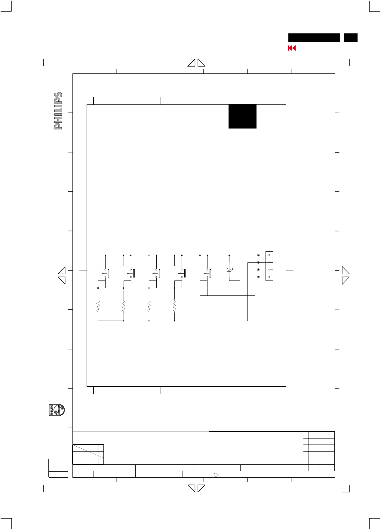
Key Control Schematic diagram
http://jdwxzlw.5d6d.com/?fromuser=华盛维修
家电维修资料网,免费下载各种维修资料
V20 107E5
Go to cover page
37
is prohibited without the written consent of the copyright
owner.
All rights reserved. Reproduction in whole or in parts
21
A
CONTROL PCB
B
A
C
B
D
C
E
SB: 57231 x28
PB: 57241
OK RightLeft
1
3
2
4
123
1891
1
3
1892
2
4
1
3
1893
2
4
3456
F1 C3
F2 C3
F3 C3
F4 D3
A
B
C
1891 D1
1892 D1
1893 D2
1894 D2
1895 D3
3891 D1
3892 D1
3893 D1
3894 D2
6891 C3
8899 C3
C
8899
JFE3309V
F1
F2
F3
F4
4
3
2
1
TO MAIN BD 1803
1
1894
2
[R]
POWER
3
4
1
1895
2
L-34GD
6891
LF
3
4
A
B
C
D
E
F
D
1/2W
12K
3891
G
E
toestemming van de auteursrechthebbende.
Alle rechten voorbehouden. Verveelvuldiging, geheel of
gedeeltelijk, is niet toegestaan dan met schriftelijke
H
[R] STANDS FOR COMPONENT RESERVED.
I
TYT12-
CLASS_NO
J
32002-12-13
NAME
Roland/Ivy Su
1
1/2W
18K
3892
123
CONTROL BOARD
47K
107E51/87
SUPERS.
DATECHECK
2
[R]
1/2W
3893
V20 107E5SETNAMECHN
2002-11-29
3894
3
3138 178 6456
1
C
KONINKLIJKE PHILIPS ELECTRONICS N.V. 2000
4
130
D
E
1
--------
1
65
F
G
H
I
J
A4
Page 38
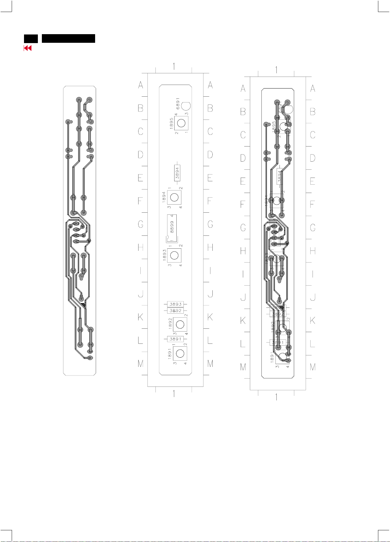
38
http://jdwxzlw.5d6d.com/?fromuser=华盛维修
家电维修资料网,免费下载各种维修资料
V20 107E5
Go to cover page
Key Control Panel C.B.A.(C)
GRID BOARD
REF LABEL SIDE
____ ____ _____
1891 M1 B
1892 K1 B
1893 H1 B
1894 F1 B
1895 C1 B
3891 L1 B
3892 K1 B
3893 J1 B
3894 E1 B
6891 B1 B
8899 G1 B
Page 39
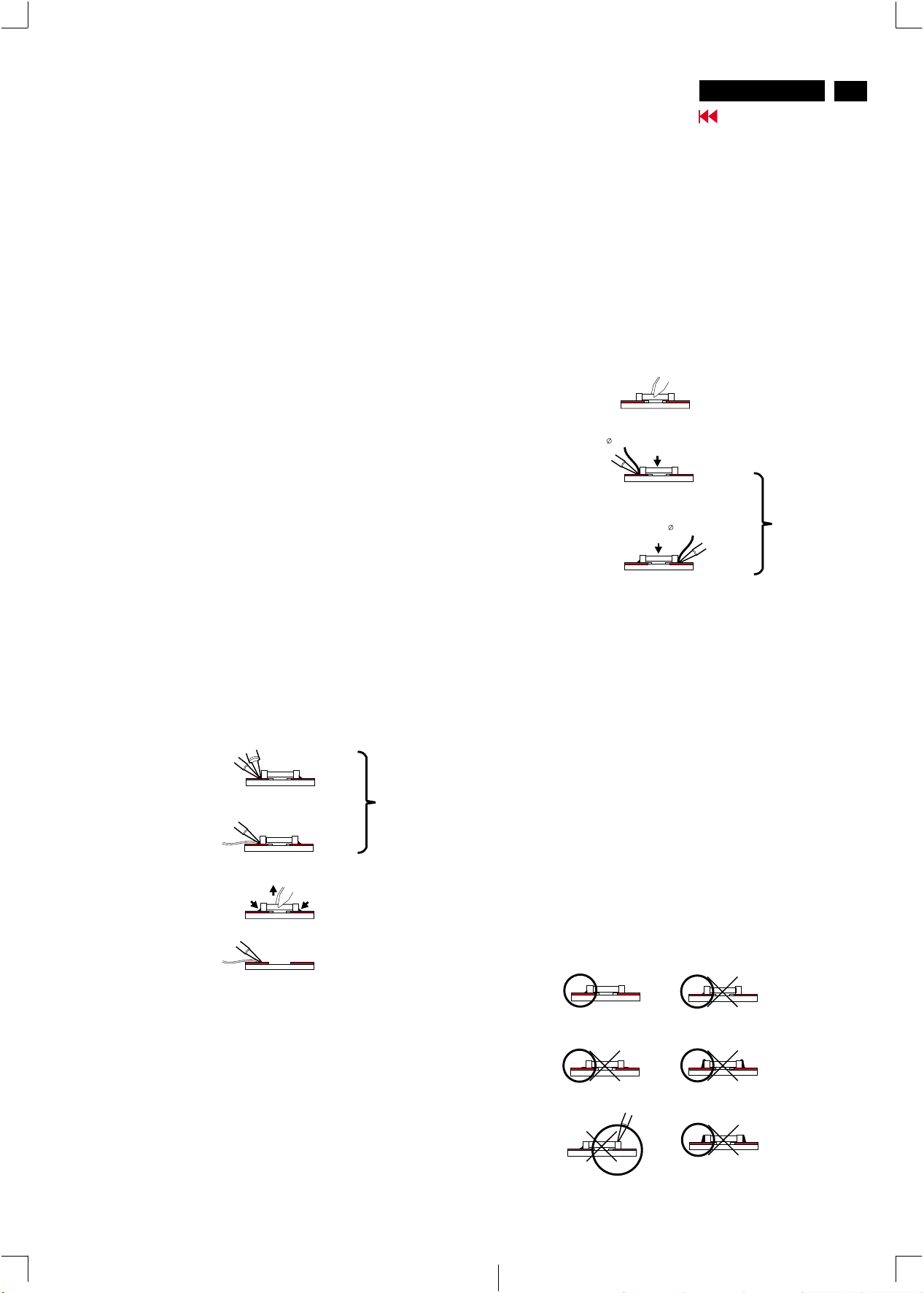
Repair Tips
http://jdwxzlw.5d6d.com/?fromuser=华盛维修
家电维修资料网,免费下载各种维修资料
V20 107E5
Go to cover page
39
0. Warning
All ICs and many other semi-conductors are susceptible to
electrostatic discharges (ESD). Careless handling during
repair can reduce life drastically. When repairing, make sure
that you are connected with the same potential as the mass
of the unit via a wrist wrap with resistance. Keep components
and tools also at the same potential !
1. Servicing of SMDs (Surface Mounted Devices)
1.1 General cautions on handling and storage
- Oxidation on the terminals of SMDs results in poor soldering.
Do not handle SMDs with bare hands.
- Avoid using storage places that are sensitive to oxidation
such as places with sulphur or chlorine gas, direct sunlight,
high temperatures or a high degree of humidity. The
capacitance or resistance value of the SMDs may be
affected by this.
- Rough handling of circuit boards containing SMDs may
cause damage to the components as well as the circuit
boards. Circuit boards containing SMDs should never be
bent or flexed. Different circuit board materials expand and
contract at different rates when heated or cooled and the
components and/or solder connections may be damaged
due to the stress. Never rub or scrape chip components as
this may cause the value of the component to change.
Similarly, do not slide the circuit board across any surface.
preferably be equipped with a thermal control (soldering
temperature: 225 to 250 C).
o
- The chip, once removed, must never be reused.
1.4 Attachment of SMDs
- Locate the SMD on the solder lands by means of tweezers
and solder the component on one side. Ensure that the
component is positioned correctly on the solder lands (see
Fig.2A).
- Next complete the soldering of the terminals of the
component (see Fiq. 2B).
Fig. 2
SOLDERING
IRON
SOLDERING TIME
< 3 sec/side
MOUNTING
e.g. A PAIR OF TWEEZERS
SOLDER
0.5 - 0.8 mm
PRESURE
PRESURE
SOLDER
0.5 - 0.8 mm
SOLDERING
IRON
A
B
2. Caution when attaching SMDs
1.2 Removal of SMDs
- Heat the solder (for 2-3 seconds) at each terminal of the
chip. By means of litz wire and a slight horizontal force,
small components can be removed with the soldering iron.
They can also be removed with a solder sucker (see Fig.
1A)
Fig. 1
DISMOUNTING
VACUUM PISTON
SOLDERING
IRON
e.g. WELLER
SOLDER TIP PT -H7
SOLDERING
IRON
SOLDER WICK
4822 321 40042
HEATING
SOLDERING
IRON
SOLDER WICK
4822 395 10159
A
e.g. A PAIR OF TWEEZERS
HEATING
B
C
- While holding the SMD with a pair of tweezers, take it off
gently using the soldering iron's heat applied to each
terminal (see Fig. 1 B).
- Remove the excess solder on the solder lands by means of
litz wire or a solder sucker (see Fig. 1C).
- When soldering the SMD terminals, do not touch them
directly with the soldering iron. The soldering should be
done as quickly as possible, care must be taken to avoid
damage to the terminals of the SMDs themselves.
- Keep the SMD's body in contact with the printed board when
soldering.
- The soldering iron to be used (approx. 30W)should
preferably be equipped with a thermal control (soldering
temperature: 225 to 250 C).
o
- Soldering should not be done outside the solder land.
- Soldering flux (of rosin) may be used, but should not be
acidic.
- After soldering, let the SMD cool down gradually at room
temperature.
- The quantity of solder must be proportional to the size of the
solder land. If the quantity is too great, the SMD might
crack or the solder lands might be torn loose from the
printed board (see Fig. 3).
Examples
Fig. 3
RIGHT
1.3 Caution on removal
- When handling the soldering.iron. use suitable pressure and
SOLDERING
IRON
be careful.
- When removing the chip, do not use undue force with the
pair of tweezers.
- The soldering iron to be used (approx. 30 W) should
Page 40
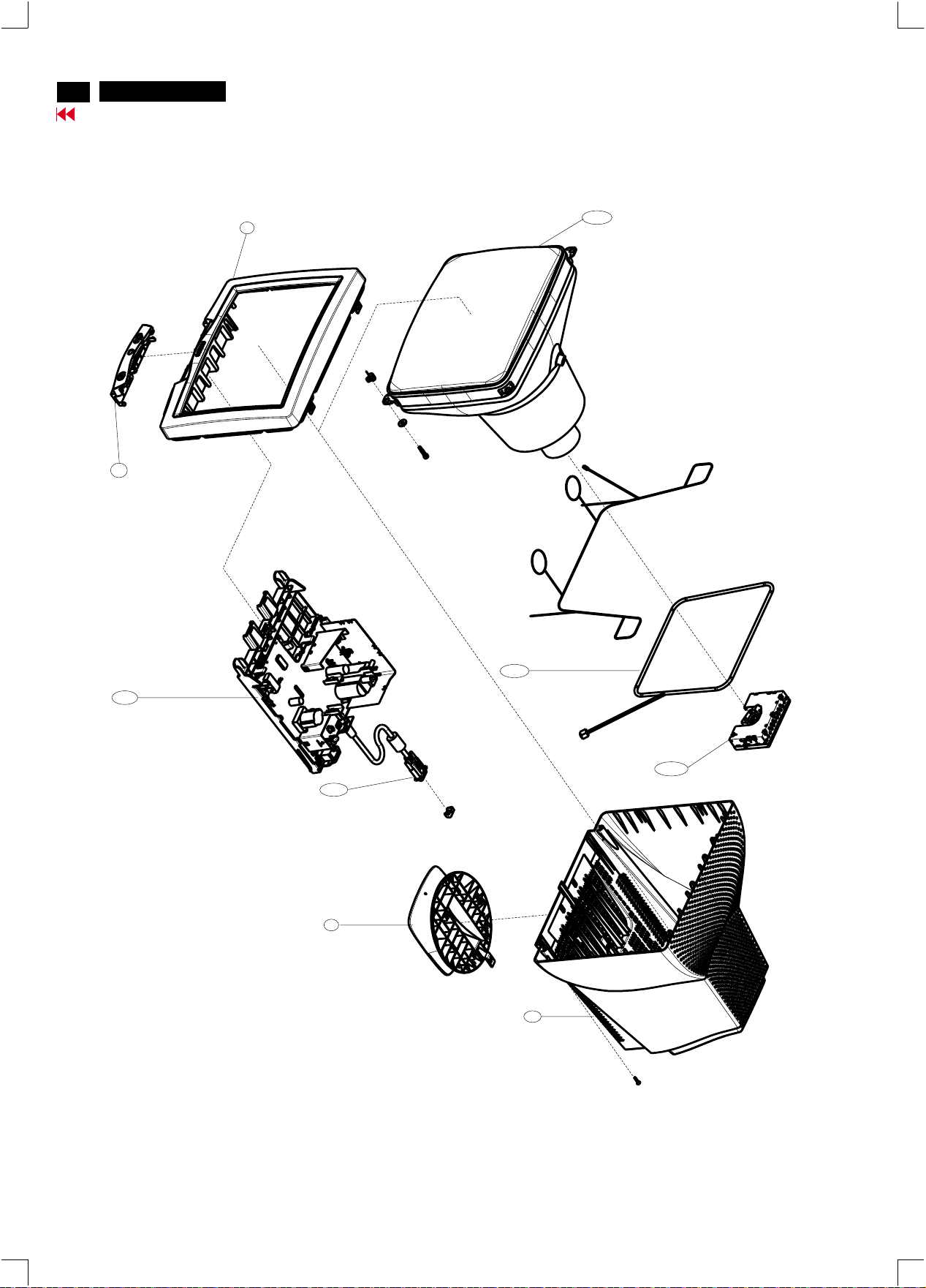
40
http://jdwxzlw.5d6d.com/?fromuser=华盛维修
家电维修资料网,免费下载各种维修资料
V20 107E5
Go to cover page
4
3138 127 53211
CHIN ASSY
1
3138 127 53221
FRONT CABINET ASSY
Exploded view
9301 879 80323
1050
17"CRT M41EHN323X160/G372B
1051
3138 178 64871
MB-1 ASSY(PHL)
1162
3138 188 76531
I/F CABLE
3
3138 127 53211
PEDESTAL ASSY
5007
3138 188 76421
COIL CORNER TDC304A
42
3138 104 59461
BACK COVER
1052
3138 178 64781
VIDEO PCB ASSY(PHL)
Page 41

Recommended Parts List
http://jdwxzlw.5d6d.com/?fromuser=华盛维修
家电维修资料网,免费下载各种维修资料
Recommended parts list of 107E51/87
0001 313812753221 FRONT CABINET ASSY
0003 313812753211 PEDESTAL ASSY
0004
313812753231 CHIN ASSY
0042 313810459461 BACK COVER
0450 313810661791 CARTON
0451 313810661801 CUSHION - TOP
0452 313810661811 CUSHION - BTM
0454 313810656581 PE BAG
0601 313811704781 E-D.F.U. ASSY
1102 242208600208 FUSE 5X20 HT 4A/250V IEC
1103 242213207402 RELAY 1P 12V 10/80A SDT -SS L
1161 243807098118 MAINSCORD(220V)-1.5M-CM30
1162 313818876531 CORD SUB-D 15/1M45/6+7 PIN G
1801 243854300061 RES XTL 12MHZ 30P HC49U B
5007 313818876421 COILCORNER TDC304A
5156 313818874321 TFM SMT LAYER SRW35EC-T84V11
5608 313817877941 LINEARITY COIL
5609 313816877381 DAF XFMR(SRW16EC-T119V3)
5610 313818876431 TFM LOT LAYER 11MM WIRE
5706 243853598058 IND FXD BEAD EMI 1MHZ 80R R
6101 932215736682 BRIGE GBU4K
6605 932214457687 DIO RECDMV32
7101 932217457687 FET POW SSS7N60B
7102 935267356112 IC TEA1507P/N1
7105 932214014667 PHOTOCOUPLER TCET1103G 4P
7155 932208697676 IC TL431ACZ-AP
7153 932208234676 IC L78L05ACZ
7301 932219292682 IC LM1237DQA/NA
7401 933922940682 IC TDA8172
7501 932219219682 IC TDA9112A
7601 934003960126 TRANS BSN254A
7604 931101054687 TRA POW TIP122(ST00)
7605 934040790127 TRA POW BU4522AF
7608 932217995687 FET POW IRF630B (FSC0)
7609 932219384687 FET POW IRFS640B
7621 933984890682 IC LM358N
7702 932216674682 IC LM2480NA
7801 823827444331 CPU,IC6148-K420PH-61A(with code)
V20 107E5
Go to cover page
41
Page 42
42
http://jdwxzlw.5d6d.com/?fromuser=华盛维修
家电维修资料网,免费下载各种维修资料
V20 107E5
Go to cover page
Spare Parts List
Parts List
CTV : 107E51/87
0001 313812753221 FRONT CABINETASSY
0003 313812753211 PEDESTAL ASSY
0004 313812753231 CHIN ASSY
0042 313810459461 BACK COVER
1050 930187980323 CRTM41EHN323X160/G372BV
Various
0450 313810661791 CARTON
0451 313810661801 CUSHION - TOP
0452 313810661811 CUSHION - BTM
0454 313810656581 PE BAG
0601 313811704781 E-D.F.U. ASSY
Accessories
1161 243807098118 MAINS CORD(220V)-1.5M
1162 313818876531 Cord SUB-D 15/1M45/6+7pin
1051 MB-1 ASSY(313817864871)
1051 313817864871 MB-1 ASSY(PHL)
1052 313817864781 VIDEO PCB ASSY (PHL)
1053 313817864561 CONTROL PCB ASSY
1102 242208600208 FUSE 5X20 HT 4A/250V IEC
1103 242213207402 RELAY 1P 12V 10/80A SDT -SS L
1106 243812800183 SWITCH
1252 313817864281 power T/R ASSY(7101)
1253 313817864291 HOR. T/R ASSY
1253 313817862891 POWER TRANS ASSY
1254 313817864301 VERT IC ASSY(7401)
1255 313817864471 TRANS IRF630B ASSY(7615)
1256 313817864481 TRANS IRF640B ASSY(7609)
2101 203831000006 CAP MPP 275V S 220N PM10 B
2103 202055490163 CERSAF NSB 250V S 2N2 PM20 B
2104 202055490163 CERSAF NSB 250V S 2N2 PM20 B
2105 203803524003 ELCAP LP 400V S 100U PM20 B
2107 203830250229 CAP MPOL 250V S 10N PM5 A
2108 202055890555 CERHDT RR 1KV S 470P PM10 A
2109 203830250099 CAP MPOL 100V S 470N PM10 A
2110 203803527303 ELCAP KM 25V S 47U PM20 A
2111 203830250151 CAP MPOL 100V S 27N PM5 A
2112 202055490158 CERSAF CD 250V S 2N2 PM20 B
2115 203831000009 CAP MPP 275V S 47N PM10 B
2152 203803511606 ELCAP REA 63V S 220U PM20 B
2153 203803521705 ELCAP GS 100V S 47U PM20 B
2154 203803513205 ELCAP RGA 16V S 1000U PM20 B
2155 203803521217 ELCAP GS 16V S 1000U PM20 B
2156 203803511222 ELCAP REA 16V S 470U PM20 A
2157 203830150151 CAP PP PPN 100V S 10N PM2 A
2158 225260808011 CER2 DC X7R 500V S 100P PM10 A
2159 202055790153 CER2 DC B 500V S 2N2 PM10 A
2160 202202000716 ELCAP GS 10V S 4700U PM20 B
2161 203830250089 CAP MPOL 100V S 10N PM10 A
2162 203803521306 ELCAP GS 25V S 47U PM20 A
2163 203803511503 ELCAP REA 50V S 4U7 PM20 A
2164 203803521207 ELCAP GS 16V S 100U PM20 A
2165 203801750221 ELCAP RE 50V S 1U PM20 R
2166 203803521701 ELCAP GS 100V S 4U7 PM20 A
2401 203803511222 ELCAP REA 16V S 470U PM20 A
2402 203803521504 ELCAP GS 50V S 47U PM20 A
2403 202055290807 CER2 DC B 50V S 1N PM10 A
2404 203803511222 ELCAP REA 16V S 470U PM20 A
2405 202055290807 CER2 DC B 50V S 1N PM10 A
2406 203830250093 CAP MPOL 100V S 22N PM10 A
2408 203830250098 CAP MPOL 100V S 330N PM10 A
2409 203801750222 ELCAP RE 50V S 2U2 PM20 R
2410 203830250221 CAP MPOL 100V S 15N PM5 A
2501 202055290794 CER2 DC B 50V S 100P PM10 A
2502 203830250212 CAP MPOL 100V S 100N PM5 A
2503 203830250089 CAP MPOL 100V S 10N PM10 A
2504 203830150173 CAP PP PPN 100V S 1N PM5 A
2505 203830250089 CAP MPOL 100V S 10N PM10 A
2506 203803513504 ELCAP RGA 50V S 4U7 PM20 A
(LGPD)
2507 203803511503 ELCAP REA 50V S 4U7 PM20 A
2509 203803527201 ELCAP KM 16V S 47U PM20 A
2510 225232512472 CER2 ML X7R 50V S 4N7 PM10 A
2511 203830250095 CAP MPOL 100V S 100N PM10 A
2512 202055290794 CER2 DC B 50V S 100P PM10 A
2513 203803521207 ELCAP GS 16V S 100U PM20 A
2514 225279508453 CER2 DC Y5V 50V 100N P8020 A
2515 203830250121 CAP MPOL 100V S 150N PM10 A
2516 203830250099 CAP MPOL 100V S 470N PM10 A
2517 203803527201 ELCAP KM 16V S 47U PM20 A
2518 203803527701 ELCAP KM 100V S 4U7 PM20 A
2519 202055290607 CER1 DC NP0 50V S 220P PM5 A
2520 203801750221 ELCAP RE 50V S 1U PM20 R
2521 225232626104 CER2 ML X7R 100V S 100N PM10 A
2601 225279508453 CER2 DC Y5V 50V 100N P8020 A
2602 203803513803 ELCAP RGA 160V S 10U PM20 B
2603 203803521701 ELCAP GS 100V S 4U7 PM20 A
2604 203830200153 CAP MPOL 250V S 68N PM10 B
2605 203830250095 CAP MPOL 100V S 100N PM10 A
2606 225232512471 CER2 ML X7R 50V S 470P PM10 A
2607 203830250121 CAP MPOL 100V S 150N PM10 A
2608 222237590634 CAP PP-MPOL 2KV5 S 4N7 PM5 B
2609 203803511606 ELCAP REA 63V S 220U PM20 B
2610 203830100163 CAP PP PPN 630V S 5N6 PM5 B
2611 203830250089 CAP MPOL 100V S 10N PM10 A
2612 203830150111 CAP PP PPN 250V S 4N7 PM5 A
2613 203830150111 CAP PP PPN 250V S 4N7 PM5 A
2614 203803523601 ELCAP BP BP 63V S 3U3 PM10 B
2615 225232626104 CER2 ML X7R 100V S 100N PM10 A
2617 225260808021 CER2 DC X7R 500V S 1N PM10 A
2618 203830100425 CAP MPP MPSA 400V S 270N PM5 B
2619 203830100304 CAP MPP MPS 250V S 560N PM5 B
2620 202055890604 CERHDT RR 2KV S 100P PM10 A
2622 203801750221 ELCAP RE 50V S 1U PM20 R
2623 203801750221 ELCAP RE 50V S 1U PM20 R
2624 202055790142 CER2 DC B 500V S 100P PM10 A
2625 225264133527 CER2 DC Z5U 1KV S 5N6 PM20 B
2626 203803511503 ELCAP REA 50V S 4U7 PM20 A
2627 203803527201 ELCAP KM 16V S 47U PM20 A
2628 225260114416 CER2 DC X7R 1KV S 470P PM10 A
2629 202202000792 ELCAP GS 250V S 33U PM20 B
2630 203803513903 ELCAP RGA 250V S 10U PM20 B
2631 203830250095 CAP MPOL 100V S 100N PM10 A
2632 203830100224 CAP MPP MPS 250V S 220N PM5 B
2634 203803521303 ELCAP GS 25V S 10U PM20 A
2635 203830250095 CAP MPOL 100V S 100N PM10 A
2636 203830150301 CAP PP PPN 250V S 10N PM5 A
2637 225232512104 CER2 ML X7R 50V S 100N PM10 A
2801 203803521201 ELCAP GS 16V S 10U PM20 A
2802 203803521207 ELCAP GS 16V S 100U PM20 A
2803 202055290594 CER1 DC NP0 50V S 22P PM5 A
2804 202055290594 CER1 DC NP0 50V S 22P PM5 A
2805 202055290598 CER1 DC NP0 50V S 47P PM5 A
2806 202055290807 CER2 DC B 50V S 1N PM10 A
2807 203801750222 ELCAP RE 50V S 2U2 PM20 R
2808 203801750222 ELCAP RE 50V S 2U2 PM20 R
2809 203801750222 ELCAP RE 50V S 2U2 PM20 R
2810 225279508453 CER2 DC Y5V 50V 100N P8020 A
2811 225279508453 CER2 DC Y5V 50V 100N P8020 A
2812 225279508453 CER2 DC Y5V 50V 100N P8020 A
3401 212211000304 RST MFLM MF1/2WS A 2R2 PM1 A
3402 212211000385 RST MFLM MF1/2WS A 12K PM1 A
3403 212211000365 RST MFLM MF1/2WS A 2K2 PM1 A
3404 212211000365 RST MFLM MF1/2WS A 2K2 PM1 A
3405 212211000317 RST MFLM MF1/2WS A 15R PM1 A
3406 212211000298 RST MFLM MF1/2WS A 1R PM1 A
3407 212211000341 RST MFLM MF1/2WS A 270R PM1 A
3408 212211000306 RST MFLM MF1/2WS A 2R7 PM1 A
3409 212211000305 RST MFLM MF1/2WS A 2R4 PM1 A
3410 212261200062 NTC DC TTC-501 S 500R PM5 A
3411 213810113822 RST CRB CFR-12 A 8K2 PM5 A
3412 213810113222 RST CRB CFR-12 A 2K2 PM5 A
3413 213810113103 RST CRB CFR-12 A 10K PM5 A
3414 213810113102 RST CRB CFR-12 A 1K PM5 A
3415 212211000372 RST MFLM MF1/2WS A 3K9 PM1 A
3416 213810113103 RST CRB CFR-12 A 10K PM5 A
3501 213810113272 RST CRB CFR-12 A 2K7 PM5 A
3502 212211000397 RST MFLM MF1/2WS A 36K PM1 A
3503 231291516203 RST MFLM MBB0207 A 62K PM1 A
3504 213810113222 RST CRB CFR-12 A 2K2 PM5 A
3505 213810113823 RST CRB CFR-12 A 82K PM5 A
3506 213810113101 RST CRB CFR-12 A 100R PM5 A
3507 213810113479 RST CRB CFR-12 A 47R PM5 A
3508 213810113471 RST CRB CFR-12 A 470R PM5 A
3509 212211000373 RST MFLM MF1/2WS A 4K3 PM1 A
3510 213810113472 RST CRB CFR-12 A 4K7 PM5 A
3511 213810113681 RST CRB CFR-12 A 680R PM5 A
3512 213810113183 RST CRB CFR-12 A 18K PM5 A
3513 213810113152 RST CRB CFR-12 A 1K5 PM5 A
3514 213810113273 RST CRB CFR-12 A 27K PM5 A
3516 212211000374 RST MFLM MF1/2WS A 4K7 PM1 A
3517 213810113102 RST CRB CFR-12 A 1K PM5 A
3518 213810113102 RST CRB CFR-12 A 1K PM5 A
3519 213810113104 RST CRB CFR-12 A 100K PM5 A
3520 213810113272 RST CRB CFR-12 A 2K7 PM5 A
3521 213810113569 RST CRB CFR-12 A 56R PM5 A
3522 213810113569 RST CRB CFR-12 A 56R PM5 A
3523 212211000453 RST MFLM MF1/2WS A 14K PM1 A
3524 231291511004 RST MFLM MBB0207 A 100K PM1 A
3525 231291515103 RST MFLM MBB0207 A 51K PM1 A
3526 213810113108 RST CRB CFR-12 A 1R PM5 A
3601 212211000352 RST MFLM MF1/2WS A 680R PM1 A
3602 213810113101 RST CRB CFR-12 A 100R PM5 A
3603 213810113103 RST CRB CFR-12 A 10K PM5 A
3604 213810113229 RST CRB CFR-12 A 22R PM5 A
3605 212010592158 RST MOX 2W RSS S 180R PM5 B
3606 212010592167 RST MOX 2W RSS S 8K2 PM5 B
3607 213810500226 RST MOX 5W RSS S 1R5 PM5 B
3608 212211000315 RST MFLM MF1/2WS A 10R PM1 A
3609 212211000369 RST MFLM MF1/2WS A 3K3 PM1 A
3610 212211000387 RST MFLM MF1/2WS A 15K PM1 A
3611 212211000393 RST MFLM MF1/2WS A 24K PM1 A
3612 213810113102 RST CRB CFR-12 A 1K PM5 A
3613 213810113102 RST CRB CFR-12 A 1K PM5 A
3614 213810113223 RST CRB CFR-12 A 22K PM5 A
3615 212211000368 RST MFLM MF1/2WS A 3K PM1 A
3616 212020200019 RST FUSE RFU1/3 A 10R PM5 A
3617 213810500402 RST MOX 2W RSS S 390R PM5 B
3618 212211000312 RST MFLM MF1/2WS A 5R6 PM1 A
3619 213810113101 RST CRB CFR-12 A 100R PM5 A
3620 212211000312 RST MFLM MF1/2WS A 5R6 PM1 A
3621 212211000319 RST MFLM MF1/2WS A 20R PM1 A
3622 232224213104 RST MGL VR37 A 100K PM5 A
3626 213810113473 RST CRB CFR-12 A 47K PM5 A
3627 213810113103 RST CRB CFR-12 A 10K PM5 A
3628 213810113223 RST CRB CFR-12 A 22K PM5 A
3629 213810113473 RST CRB CFR-12 A 47K PM5 A
3630 213810113103 RST CRB CFR-12 A 10K PM5 A
3631 213810113103 RST CRB CFR-12 A 10K PM5 A
3632 213811273152 RST CRB CFR-25 A 1K5 PM5 A
3633 212020200002 RST FUSE RFS1/2 A 2R2 PM5 A
3634 213810113101 RST CRB CFR-12 A 100R PM5 A
3635 213810113223 RST CRB CFR-12 A 22K PM5 A
3636 213810500202 RST MOX 2W RSS S R47 PM5 B
3637 212010593619 RST MOX 2W RSS S 1K5 PM5 B
3638 213811273184 RST CRB CFR-25 A 180K PM5 A
3639 212020200015 RST FUSE RFU1/3 A 1R PM5 A
3640 213810113182 RST CRB CFR-12 A 1K8 PM5 A
3641 213810113473 RST CRB CFR-12 A 47K PM5 A
3642 232224213475 RST MGL VR37 A 4M7 PM5 A
3643 232224213434 RST MGL VR37 A 430K PM5 A
3644 213810113102 RST CRB CFR-12 A 1K PM5 A
3645 213810113472 RST CRB CFR-12 A 4K7 PM5 A
3646 213810113472 RST CRB CFR-12 A 4K7 PM5 A
3647 213810113274 RST CRB CFR-12 A 270K PM5 A
3648 231291512204 RST MFLM MBB0207 A 220K PM1 A
3649 231291512204 RST MFLM MBB0207 A 220K PM1 A
3650 231291512204 RST MFLM MBB0207 A 220K PM1 A
3651 231291512204 RST MFLM MBB0207 A 220K PM1 A
3652 212211000392 RST MFLM MF1/2WS A 22K PM1 A
3653 212211000383 RST MFLM MF1/2WS A 10K PM1 A
3654 213811273475 RST CRB CFR-25 A 4M7 PM5 A
3656 213810113154 RST CRB CFR-12 A 150K PM5 A
3657 213810113154 RST CRB CFR-12 A 150K PM5 A
3658 213810113103 RST CRB CFR-12 A 10K PM5 A
3659 213810113683 RST CRB CFR-12 A 68K PM5 A
3660 213810113184 RST CRB CFR-12 A 180K PM5 A
3801 213810113332 RST CRB CFR-12 A 3K3 PM5 A
3802 213810113472 RST CRB CFR-12 A 4K7 PM5 A
3803 213810113472 RST CRB CFR-12 A 4K7 PM5 A
3804 213810113472 RST CRB CFR-12 A 4K7 PM5 A
3805 213810113101 RST CRB CFR-12 A 100R PM5 A
3806 213810113101 RST CRB CFR-12 A 100R PM5 A
3807 213810113101 RST CRB CFR-12 A 100R PM5 A
3808 213810113101 RST CRB CFR-12 A 100R PM5 A
3809 213810113561 RST CRB CFR-12 A 560R PM5 A
3810 213810113122 RST CRB CFR-12 A 1K2 PM5 A
3811 213810113152 RST CRB CFR-12 A 1K5 PM5 A
3812 213810113472 RST CRB CFR-12 A 4K7 PM5 A
3813 213810113472 RST CRB CFR-12 A 4K7 PM5 A
3814 213810113472 RST CRB CFR-12 A 4K7 PM5 A
3816 213810113109 RST CRB CFR-12 A 10R PM5 A
3817 213810113101 RST CRB CFR-12 A 100R PM5 A
3818 213810113101 RST CRB CFR-12 A 100R PM5 A
3819 213810113561 RST CRB CFR-12 A 560R PM5 A
3820 212211000392 RST MFLM MF1/2WS A 22K PM1 A
3821 213810113123 RST CRB CFR-12 A 12K PM5 A
3822 213810113473 RST CRB CFR-12 A 47K PM5 A
3823 213810113472 RST CRB CFR-12 A 4K7 PM5 A
3824 213810113472 RST CRB CFR-12 A 4K7 PM5 A
3825 213810113222 RST CRB CFR-12 A 2K2 PM5 A
Page 43
Spare Parts List (Continued)
http://jdwxzlw.5d6d.com/?fromuser=华盛维修
家电维修资料网,免费下载各种维修资料
5101 313818876471 FIL MAINS 16MH 1A2 163Y1R2
5102 313816872631 BEAD COIL
5103 313816872631 BEAD COIL
5151 242253600038 IND FXD TSL0808 S 22U PM10 A
5152 313816872631 BEAD COIL
5153 242253600036 IND FXD TSL0808 S 100U PM10 A
5154 242253600036 IND FXD TSL0808 S 100U PM10 A
5155 242253600036 IND FXD TSL0808 S 100U PM10 A
5156 313818876561 TFM SMT LAYER SRW35EC-T84V
5157 243853598058 IND FXD BEAD EMI 100MHZ 80R A
5501 313816872631 BEAD COIL
5601 313812875441 DRIVER XFORM
5602 313816872631 BEAD COIL
5603 313816872631 BEAD COIL
5604 313816872631 BEAD COIL
5605 313816872631 BEAD COIL
5606 242253600037 IND FXD TSL0808 S 3700U PM5 A
5607 313818876481 COI CHOKE130UH 173MOHM Dr14
5608 313817877941 LINEARITY COIL
5609 313816877381 DAF XFMR (SRW16EC-T119V003)
5610 313818876431 TFM LOT LAYER 11MM WIRE
5611 823827444561 180 UH CHOKE
5612 243853598058 IND FXD BEAD EMI 100MHZ 80R A
5614 243853598058 IND FXD BEAD EMI 100MHZ 80R A
5616 243853598058 IND FXD BEAD EMI 100MHZ 80R A
6101 932215736682 BRIDGE GBU4K (PAJI) B
6102 933783720673 DIO REC RGP10M A (GI00) A
6103 933751660673 DIO REC RGP10D A (GI00) A
6104 932210411673 DIO SIG 1SS133 A (RHM0) A
6105 932210411673 DIO SIG 1SS133 A (RHM0) A
6106 933083990133 DIO SIG 1N4148 A (PHSE) A
6151 932211574682 DIO REC 31DF4-FC5 (NIEC0 B
6152 933497950673 DIO REC RGP10J A (GI00) A
6153 933730980133 DIO REC BYV36C A (PHSE) A
6154 933957760673 DIO REC SB140 A (GI00) A
6155 932210346673 DIO REC SBYV27-200 A (GI00) A
6156 933751660673 DIO REC RGP10D A (GI00) A
6157 933166850133 DIO REG BZX79-B8V2 A (PHSE) A
6158 933751660673 DIO REC RGP10D A (GI00) A
6159 932210411673 DIO SIG 1SS133 A (RHM0) A
6160 932210411673 DIO SIG 1SS133 A (RHM0) A
6161 933117760133 DIO REG BZX79-C7V5 A (PHSE) A
6162 933751660673 DIO REC RGP10D A (GI00) A
6401 932210346673 DIO REC SBYV27-200 A (GI00) A
6402 933083990133 DIO SIG 1N4148 A (PHSE) A
6501 932210411673 DIO SIG 1SS133 A (RHM0) A
6502 932210411673 DIO SIG 1SS133 A (RHM0) A
6503 933083990133 DIO SIG 1N4148 A (PHSE) A
6504 932210411673 DIO SIG 1SS133 A (RHM0) A
6505 933712640673 DIO REG BZX55-B5V6 A (VISH) A
6506 932210411673 DIO SIG 1SS133 A (RHM0) A
6507 933751660673 DIO REC RGP10D A (GI00) A
6508 933083990133 DIO SIG 1N4148 A (PHSE) A
6509 932210411673 DIO SIG 1SS133 A (RHM0) A
6510 933189210133 DIO SIG BAV21 A (PHSE) A
6601 933083990133 DIO SIG 1N4148 A (PHSE) A
6602 932210346673 DIO REC SBYV27-200 A (GI00) A
6603 932210346673 DIO REC SBYV27-200 A (GI00) A
6606 933189210133 DIO SIG BAV21 A (PHSE) A
6607 933189210133 DIO SIG BAV21 A (PHSE) A
6609 933497950673 DIO REC RGP10J A (GI00) A
6610 933497950673 DIO REC RGP10J A (GI00) A
6611 933929870683 DIO REC EGP30G A (GI00) R
6612 933751650683 DIO REC RGP15K A (GI00) R
6613 933497950673 DIO REC RGP10J A (GI00) A
6614 933751660673 DIO REC RGP10D A (GI00) A
6615 932210411673 DIO SIG 1SS133 A (RHM0) A
6801 933957760673 DIO REC SB140 A (GI00) A
6802 933712640673 DIO REG BZX55-B5V6 A (VISH) A
6803 932203213673 DIO REG MTZJ5.6B A (RHM0) A
6804 932203216673 DIO REG MTZJ12C A (RHM0) A
6805 932203213673 DIO REG MTZJ5.6B A (RHM0) A
7102 935267356112 IC TEA1507P/N1 (PHSE) L
7103 933953420676 TRA SIG TBC338-40 (TOSJ) A
7105 932214014667 OPT CP TCET1103(G) (VISH) L
7151 933953420676 TRA SIG TBC338-40 (TOSJ) A
7152 933826850126 THYRIS BT169B (PHSE) A
7153 932208234676 IC L78L05ACZ (ST00) A
7154 932209011673 TRA SIG BC548C (KEC0) A
7155 932208697676 IC TL431ACZ-AP S (ST00) A
7402 932209011673 TRA SIG BC548C (KEC0) A
7403 933567130126 TRA SIG BC517 (PHSE) A
7404 933567120126 TRA SIG BC516 (PHSE) A
7501 932219219682 IC TDA9112A (ST00) L
7502 932214472676 TRA SIG BF423 (KEC0) A
7503 932210142676 TRA SIG BC558C (KEC0) A
7601 934003960126 FET SIG BSN254A (PHSE) A
7602 932209011673 TRA SIG BC548C (KEC0) A
7603 932210142676 TRA SIG BC558C (KEC0) A
7606 933953420676 TRA SIG TBC338-40 (TOSJ) A
7608 932217995687 FET POW IRF630B (FSC0) L
7611 932209011673 TRA SIG BC548C (KEC0) A
7612 932209011673 TRA SIG BC548C (KEC0) A
7613 933953420676 TRA SIG TBC338-40 (TOSJ) A
7614 933179570126 TRA SIG BC328-40 (PHSE) A
7616 934025870126 TRA SIG MPSA44 (PHSE) A
7617 932209011673 TRA SIG BC548C (KEC0) A
7801 823827444331 CPU IC 6148-K420PH-61A
7802 932212662682 IC M24C16-BN6 (ST00) L
7803 932209011673 TRA SIG BC548C (KEC0) A
8113 313818876211 CBLE FAST/110/RING TERM AWG18
8501 313818875991 CBLE OE 12/250/12 OE AWG24KING
8602 313818876261 CBLE OE/805/OE BENT AWG22
1052 Video PCB ASSY(313817864781)(PHL)
2301 225232512104 CER2 ML X7R 50V S 100N PM10 A
2302 225232512104 CER2 ML X7R 50V S 100N PM10 A
2303 225232512104 CER2 ML X7R 50V S 100N PM10 A
2304 225232512104 CER2 ML X7R 50V S 100N PM10 A
2305 203830150173 CAP PP PPN 100V S 1N PM5 A
2306 203830250111 CAP MPOL 100V S 56N PM10 A
2307 203803527501 ELCAP KM 50V S 10U PM20 A
2308 202055290606 CER1 DC NP0 50V S 180P PM5 A
2309 203801750222 ELCAP RE 50V S 2U2 PM20 R
2310 202055290591 CER1 DC NP0 50V S 12P PM5 A
2311 202055290591 CER1 DC NP0 50V S 12P PM5 A
2312 202203100143 ELCAP KM 10V S 470U PM20 A
2313 202055290591 CER1 DC NP0 50V S 12P PM5 A
2314 225232512104 CER2 ML X7R 50V S 100N PM10 A
2315 225232512104 CER2 ML X7R 50V S 100N PM10 A
2316 225232512104 CER2 ML X7R 50V S 100N PM10 A
2317 225232626104 CER2 ML X7R 100V S 100N PM10 A
2318 225232626104 CER2 ML X7R 100V S 100N PM10 A
2319 225232626104 CER2 ML X7R 100V S 100N PM10 A
2702 225232512104 CER2 ML X7R 50V S 100N PM10 A
2703 203803527701 ELCAP KM 100V S 4U7 PM20 A
2704 203803513702 ELCAP RGA 100V S 10U PM20 A
2708 203803522801 ELCAP BP NK 160V S 1U PM20 A
2709 242254945382 SURGE PROTECT SGP-201M-DRF A
2710 203830250089 CAP MPOL 100V S 10N PM10 A
2711 203803522801 ELCAP BP NK 160V S 1U PM20 A
2712 242254945382 SURGE PROTECT SGP-201M-DRF A
2713 203803522801 ELCAP BP NK 160V S 1U PM20 A
2714 242254945382 SURGE PROTECT SGP-201M-DRF A
2715 225232512104 CER2 ML X7R 50V S 100N PM10 A
2716 202055790686 CER2 DC B 500V S 330P PM10 A
2717 225261216226 CER2 DC Y5P 2KV S 2N2 PM10 B
2718 225232626104 CER2 ML X7R 100V S 100N PM10 A
3301 213810113759 RST CRB CFR-12 A 75R PM5 A
3302 213810113759 RST CRB CFR-12 A 75R PM5 A
3303 213810113759 RST CRB CFR-12 A 75R PM5 A
3304 213810113151 RST CRB CFR-12 A 150R PM5 A
3305 213810113151 RST CRB CFR-12 A 150R PM5 A
3306 213810113151 RST CRB CFR-12 A 150R PM5 A
3307 213810113472 RST CRB CFR-12 A 4K7 PM5 A
3308 213810113103 RST CRB CFR-12 A 10K PM5 A
3309 213810113472 RST CRB CFR-12 A 4K7 PM5 A
3310 213810113472 RST CRB CFR-12 A 4K7 PM5 A
3311 213810113479 RST CRB CFR-12 A 47R PM5 A
3312 213810113479 RST CRB CFR-12 A 47R PM5 A
3313 213810113103 RST CRB CFR-12 A 10K PM5 A
3314 213810113472 RST CRB CFR-12 A 4K7 PM5 A
V20 107E5
43
Go to cover page
3315 213810113182 RST CRB CFR-12 A 1K8 PM5 A
3316 213810113102 RST CRB CFR-12 A 1K PM5 A
3317 213810113101 RST CRB CFR-12 A 100R PM5 A
3318 213810113101 RST CRB CFR-12 A 100R PM5 A
3319 213810113101 RST CRB CFR-12 A 100R PM5 A
3320 213810113479 RST CRB CFR-12 A 47R PM5 A
3321 213810113479 RST CRB CFR-12 A 47R PM5 A
3701 213810113101 RST CRB CFR-12 A 100R PM5 A
3702 212211000328 RST MFLM MF1/2WS A 82R PM1 A
3703 213810113274 RST CRB CFR-12 A 270K PM5 A
3704 213810113121 RST CRB CFR-12 A 120R PM5 A
3705 212211000328 RST MFLM MF1/2WS A 82R PM1 A
3706 213810113274 RST CRB CFR-12 A 270K PM5 A
3707 213810113101 RST CRB CFR-12 A 100R PM5 A
3708 212211000328 RST MFLM MF1/2WS A 82R PM1 A
3709 213810113274 RST CRB CFR-12 A 270K PM5 A
3710 212211000361 RST MFLM MF1/2WS A 1K5 PM1 A
3711 212211000325 RST MFLM MF1/2WS A 47R PM1 A
3712 212010590825 RST MOX 1W RSS A 15K PM5 A
3713 213810113102 RST CRB CFR-12 A 1K PM5 A
3714 213810113101 RST CRB CFR-12 A 100R PM5 A
3715 213810113339 RST CRB CFR-12 A 33R PM5 A
5301 313816872621 BEAD COIL (BF30TA-2.5X3X1B)
5302 242254942026 IND FXD BEAD EMI 100MHZ 50R A
5303 242254942026 IND FXD BEAD EMI 100MHZ 50R A
5304 242254942026 IND FXD BEAD EMI 100MHZ 50R A
5702 242253597608 IND FXD SPT0305 A 1U8 PM10 R
5703 823827444551 0.56 UH HF CHOKE
5704 823827444551 0.56 UH HF CHOKE
5705 313817874201 COIL 0.68UH PM10
5706 243853598058 IND FXD BEAD EMI 100MHZ 80R A
5707 313816872621 BEAD COIL (BF30TA-2.5X3X1B)
5708 242253597608 IND FXD SPT0305 A 1U8 PM10 R
5709 313816872621 BEAD COIL (BF30TA-2.5X3X1B)
6314 932210411673 DIO SIG 1SS133 A (RHM0) A
6701 932210412673 DIO SIG 1SS244 A (RHM0) A
6702 932210412673 DIO SIG 1SS244 A (RHM0) A
6703 932210412673 DIO SIG 1SS244 A (RHM0) A
6704 932210412673 DIO SIG 1SS244 A (RHM0) A
6705 933189210133 DIO SIG BAV21 A (PHSE) A
6706 932210412673 DIO SIG 1SS244 A (RHM0) A
6707 933189210133 DIO SIG BAV21 A (PHSE) A
6708 932210412673 DIO SIG 1SS244 A (RHM0) A
6709 933189210133 DIO SIG BAV21 A (PHSE) A
6710 932210411673 DIO SIG 1SS133 A (RHM0) A
6711 932210411673 DIO SIG 1SS133 A (RHM0) A
6712 933751660673 DIO REC RGP10D A (GI00) A
6713 933957760673 DIO REC SB140 A (GI00) A
6714 933117810133 DIO REG BZX79-C12 A (PHSE) A
7301 932219292682 IC LM1237DQA/NA (NSC0) L
7702 932216674682 IC LM2480NA (NSC0) L
1053 CONTROL PCB ASSY
1053 313817864561 CONTROL PCB ASSY
3891 212211000385 RST MFLM MF1/2WS A 12K PM1 A
3892 212211000389 RST MFLM MF1/2WS A 18K PM1 A
3893 212211000401 RST MFLM MF1/2WS A 47K PM1 A
5007 313818876421 COIL CORNER TDC304 A
6891 932218424682 LED VS L-34GD (KIEL) B
Page 44
44
http://jdwxzlw.5d6d.com/?fromuser=华盛维修
家电维修资料网,免费下载各种维修资料
V20 107E5
Go to cover page
Item 12NC Description 12NC Description
1050 930190740323 CRT M41LFQ903X39(LA) (LGPD) B
1050 930191170323 CRT M41LFQ903X39(LA)M (LGPD) B
1050 823827444381 CRT M41KXU100XX084(SNP)
1050 930190323323 CRT M41EHN323X160/G372BF (LGPD
1050 932217270682 CRT M41AGE83X46C(PLD) (CPT0) B
1051 313817864871 MB-1 ASSY (PHL)
1051 313817864511 MAIN PCB ASSY (LG)
1051 313817864521 MAIN PCB ASSY(ORI)
1051 313817864531 MAIN PCB ASSY(PHL)
1051 313817864541 MAIN PCB ASSY(CPT)
1052 313817864781 V/B ASSY
1052 313817864551 VB ASSY (LG,CPT,OR)
1052 313817864771 VB ASSY(PHL)
1050 930187980323 CRT M41EHN323X160/G372BV (LGPD
1050 930190277323 CRT M41EHN323X160/G372LV (LGPD
Item 12NC Description 12NC Description
0201 313811576451 RATING LABEL 313811577021 RATING LABEL
0450 313810661791 CARTON 313810661981 CARTON
1161 243807098118 MAINSCORD (220V)-1.5M -CM3000 313811875011 MAINSCORD UL 10A 1M5 DET PDS
1161 313817874701 MAIN CORD (1.5M. EUROPEAN) 313812876251 MAINS CORD
Spare parts list(Different List)
863900013531(107E51/87) 863900012714(107E51/00)
863900012714(107E51/00) 863900013525(107E51/74)
863900012713(107E50/00) 863900012714(107E51/00)
Item 12NC Description 12NC Description
1050 930190710323 CRT M41LFQ903X39(LU) (LGPD) B 930190740323 CRT M41LFQ903X39(LA) (LGPD) B
1050 930191180323 CRT M41LFQ903X39(LU)M (LGPD) B 930191170323 CRT M41LFQ903X39(LA)M (LGPD) B
1050 823827444621 CRT M41KXU100XX084(SNTP) 823827444381 CRT M41KXU100XX084(SNP)
1050 930190325323 CRT M41EHN323X160/P372BF (LGPD 930190323323 CRT M41EHN323X160/G372BF (LGPD
1050 932217270682 CRT M41AGE83X46C(PLD) (CPT0) B
1051 313817865411 MB-1 ASSY (LG) 313817864511 MAIN PCB ASSY (LG)
1051 313817865421 MB-2 ASSY (ORI) 313817864521 MAIN PCB ASSY(ORI)
1051 313817865431 MB-3 ASSY (PHL) 313817864531 MAIN PCB ASSY(PHL)
1051 313817864541 MAIN PCB ASSY(CPT)
0001 313812753461 FRONT CABINET ASSY 313812753221 FRONT CABINET ASSY
0004 313812753471 CHIN ASSY 313812753231 CHIN ASSY
0042 313810460121 BACK COVER 313810459461 BACK COVER
0201 313811577301 RATING LABEL 313811576451 RATING LABEL
0450 313810662171 CARTON 313810661791 CARTON
0213 313811576551 LABEL-EEPROM (CPT)
3617 213810500402 RST MOX 2W RSS S 390R PM5 B 213810500402 RST MOX 2W RSS S 390R PM5 B
7610 933737040676 TRA SIG TBC547C (TOSJ) A 933237790126 TRA SIG BC547C (PHSE) A
7610 933237790126 TRA SIG BC547C (PHSE) A 933737040676 TRA SIG TBC547C (TOSJ) A
5007 313818876411 COIL CORNER TDC304 313818876421 COIL CORNER TDC304 A
5007 313818876391 COI DEGAUS 62-0209-02 313818876401 COI DEGAUS 62-0209-03
8055 313818876251 CBLE EARTH 462/272 313818876251 CBLE EARTH 462/272
8055 313818876281 CBLE EARTH 462/272 107E5 313818876281 CBLE EARTH 462/272 107E5
0041 313810460091 FRONT CABINET 313810459421 FRONT CABINET
0045 313810460101 CHIN 313810459431 CHIN
0022 313810460131 TRAY 313810459441 TRAY
Page 45
A. Power Supply Failure
http://jdwxzlw.5d6d.com/?fromuser=华盛维修
家电维修资料网,免费下载各种维修资料
Repair Flow Chart
V20 107E5
Go to cover page
9
45
1. Sympton :
no startup sound
LED light off
2. Sympton :
hicup mode with
startup sound or
blinking LED
7155/7152/7154
check
check 7102 pin8
100V<pin8<380V
NO
check
1101/6101/
7101/2106
Turn power off
check the resistance for
all output voltages+50,
76,12,-12,+6,+5,
check 6151~6158 short?
check 7105
open circuit
Ok
check 7102
pin1 > 2V
NO
check
7105/3125
3112/6105
replace 7102
check 7102
pin 1 < 13.5V
OVP possibly active
No
check 6104
Ok
No
Ok
check 7102
pin 5=2.4V
NO
replace 7102
check
6102
OK
OCP possibly active
check 3105
3106~3109,7101,6103
check 7102
Ok
pin6 output ?
check 7102
pin 5
No
Ok
check
6165/3107/
3105/7101
check
pin6>8V
NO
OK
replace 5156
replace 5156
7102 pin4 DEMAG
possibly active
short 7154 pinC
Ok
check CPU pin 17
and 7803emitter
Page 46
46
http://jdwxzlw.5d6d.com/?fromuser=华盛维修
家电维修资料网,免费下载各种维修资料
Go to cover page
9
B.Video
Repair Flow
1.Sympton :
(with wite pattern)
no picture
green LED on
V20 107E5
Repair Flow Chart (Continued)
rough check for R,G, B
1. video input= 0.7V
2. 7301video output =2.5V
3. 7701 video output > 35Vpp
check heater
= + 6.3V
EHT=25KV
check Xray prot.
7501 pin25
check blanking
7501 pin3
check
No
check blanking
Ok
7501 pin3
Ok
check
VG1 < -150V
No
check
R,G,B output
30<2713<80
30<2711<80
30<2708<80
Ok
check
VG2 > 450V
2.Sympton :
no video (or dim),
only raster with/without retrace line
green LED on
check 7301 pin22
2V< ABL < 5V
check 7301
Pin24 HFLB
check
7501 pin16
check 7301
Pin1 CLBL
Ok
OkNo
Ok
check Vg1
Vg1 = -30V
check 7301
pin 6,7,9
input swing
No
replace IF
cable
replace 7301
No turn down Vg2
check 7701
pin 6, 7,9
input swing
Ok
replace 7701
check cathod
+83V,3759
check 7701
pin 1,2,3
output swing
Page 47
C. Horizontal deflection
http://jdwxzlw.5d6d.com/?fromuser=华盛维修
家电维修资料网,免费下载各种维修资料
output repair flow :
Repair Flow Chart (Continued)
V20 107E5
Go to cover page
9
47
1. Sympton :
without
H-deflection.
2. Sympton :
East /West
corr.
check Hsync
replace 5610
7606 base
check 2639
parabola
exist
check
180V
check Hsync
7503 base
Ok
6602,7601,7602
check
7602 ~ 7604
parabola exist
check Hsync
check Hsync
7603 drain
No
check
check 7501
parabola exist
7501 pin10
Ok
Pin24
check Hsync
7501 pin6
No
refer 7501 check list
or replace 7501
refer 7501
check list
3. Sympton :
H-linearity
(full freq. range)
4. Sympton :
Rotation
5. Sympton :
H_dc shift
enter factory mode
check linearity data
in eeprom
check
7403,7404
check
1603
check 7402
check
3651
check
3619
7606
check cpu
7801
pin 28,29,30
check
3413
check
3620
replace 5608
check cpu
7801 pin4
control range
6. Sympton :
Focus
enter OSD
function
disable morier
check
7616collector
7501 pin 32
check
check
5609
Page 48
48
http://jdwxzlw.5d6d.com/?fromuser=华盛维修
家电维修资料网,免费下载各种维修资料
9
V20 107E5
Go to cover page
Repair Flow Chart (Continued)
D. Vertical Deflection Failure
Sympton :
one horizontal line
V_size is abnormal
too large/small
basic check
+12/-12V
check
3402,3403
3415
good
No
check
7401
Ok
check
3412,3411
check
6401
good?
No
check
7401
Ok
Ok
check 7501
Pin13,pin14 ramp
exist ?
No
check
7501
Page 49
Repair Flow Chart (Continued)
http://jdwxzlw.5d6d.com/?fromuser=华盛维修
家电维修资料网,免费下载各种维修资料
V20 107E5
Go to cover page
9
49
E. CPU
check list
Basic Check
31. H-EHT
36,37,38(Q3,Q2,Q1)
S-cap switch
33,34,40,41
Hsync / Vsync
check cpu pin6= 5V
pin9/pin8=12MhZ
pin7=gnd
H size compensation for
the load variance
check Q1-Q2
Pin36~38
low:0
hi :1
check sync.
Hsync_in=pin40
Vsync_in=pin41
Hsync_out=pin34
Vsync_out=pin33
70K S-CAPACITOR SWITCH TABLE
Hor. Freq.(KHz)
< 27.00 0 0
27.50-33.24 0 0
33.24-36.51 1 1
36.51-42.38 1 1
42.38-45.07 0 0
45.07-53.10 0 1
53.10-58.25 0 1
58.25-61.89 1
61.89-66.00 1 0
> 66.00 1 1
Q1 Q2
1 . Normal
Fhout=Fhin
Fvout=Fvin
2. Self test
Hout=48Khz
Fvout=72Hz
3.sync out of rang
Fhin>72.8kHz,<28kHz
Fvin>168Hz, <45Hz
Q3
0
0
0
0
1
1
1
0
1
1
1
18. Blanking
(mute)
20, 27,22 P.S.
LED
23. Degauss
5, Reset
check pin18
normal : low
change timing : Hi
pin 27 STBY
pin 22 OFF
check
active=hi
no active=low
check
from 5V to 0V
power saving pin27 pin22
normal hi hi
standby low hi
off low low
check
2801 / 3801
Page 50
50
http://jdwxzlw.5d6d.com/?fromuser=华盛维修
家电维修资料网,免费下载各种维修资料
9
V20 107E5
Go to cover page
Repair Flow Chart (Continued)
4. Rotation
30. ABL-CON
21,29 Keypad
24. Selftest
check
output from 0V to 5V
check
output from 0V to 5V
check key
Enter,Up,Down,Left,Right keys
check pin24
1.no H/V sync & IF cable pin5 floating - show msg.
2.H/V sync exist & IF cable pin5 to ground - normal
3.H/V sync non-exist & IF cable pin5 to gnd -power saving
4.After 1802&1803 pressed on, then power on
(1106) with IFcable pin5 -factory mode
5.After 1802&1803 pressed on, then power on
(1106) without IFcable pin5 -burn in mode
check 3811, 2812
3825~3820
25,26. DDC bus
10,11. IIC bus
12, VCLK
EEPROM
28. H-linearity
check idle status
sda=pin25=hi
scl=pin26=hi
check idle status
Sda=pin10=hi
Scl=pin11=hi
check 7802 pin 7
Low : write enable
Hi : write disable
check
output from 0V to 5V
check
6802,6803
check
7802 M24C16
7501 TDA9112a
7301 TDAlm1237
Page 51
Repair Flow Chart (Continued)
http://jdwxzlw.5d6d.com/?fromuser=华盛维修
家电维修资料网,免费下载各种维修资料
V20 107E5
Go to cover page
9
51
F. TDA9112a
Check List
12. HFLB
(from H.defl)
25. Xray
(from LOT)
14.15.16,28
B+ control
Basic check
Vcc>9V
during startup
if no exist
if active
a pin14 amplify pin5 and it compare to pin4
b. Pin15 generate the saw_tooth wave
c. Pin16 input voltage for the square output waveform
d. Pin28 pwm output to 7601 & 7602 base
Vcc=pin29=12V
gnd =pin27=0v
Pin12
CLBL=hi
Pin3= Hunlock = floating
Pin5 = Hpll2 = 0V
pin6 = HDRV = floating
pin8 = BDRV = flaoating
Pin23 = Vout2 = floating
pin16 = CLBL= Hi
inhibit pin28 output
if pin14 is pulled to
ground by 7613,7614
26. HDRV
24.EWDRV
23 Vout
1,2
Vsync,Hsync
to H_deflection.
7601 base
to H_deflection
east/west control
7602 base
differential input
to 7401 pin 1, 7
the input sync from
cpu pin 40,41
Vertical blank will be activated = hi
1.pin5 = softstart pll2 = 0V
3. V-BLK
2.pin3 = pll1 is unlock in searching mode
3.pin12 = HFLB no exist
4.pin25 = Xray once actived
5.pin29 = Vcc < 9V
Page 52
52
http://jdwxzlw.5d6d.com/?fromuser=华盛维修
家电维修资料网,免费下载各种维修资料
9
V20 107E5
Go to cover page
Repair Flow Chart (Continued)
3. Hunlock
30. IIC scl = hi
31 IIC sda = hi
18 EHT_compen.
19,20,22
VAGC,VREF,VCAP
Hunlock pin is floating while pll1(pin9) is
unlock in searching mode
the initial sequence of IIC IC
7501,7301
compensate for the V_size
owing the load variation
Pin19 determin the AGC
Pin20,pin22 determin frequency
50Hz< freq. <160Hz
Pin9 determin the
4,6,8,9
Hpll1,Hbuf,Href, Hcap
5. PLL2
32. Focus to 7616 for the V dynamic focus
1.compare the HFLB and control the phase of HDRV
2.softstart
pll1 loop filter
pin 4,6,8 H-Freq
working range
compensate for the H_size owing the load variation17 EHT_compen.
30K<freq.<71KHz
Page 53
GENERAL PRODUCT SPECIFICATION
http://jdwxzlw.5d6d.com/?fromuser=华盛维修
家电维修资料网,免费下载各种维修资料
17" 107E5 ;70KHz General Specification (Sheet 590)
=====================================================
FEATURES / BENEFITS
- EXTREMELY HIGH MTBF (OVER 75K HRS, EXCLUDING CRT)
- PROFESSIONAL LOOK, WITH NON-FLAMMABLE CABINET (94V-0)
- USER'S CONTROLS
. FRONT MOUNTED CONTROLS FOR EASY ACCESS
- BETTER DISPLAY PERFORMANCE
. FINER CRT DOT PITCH (0.27 MM)
. FULL SCREEN SIZE APPLICATION
. REAL MULTI-FREQ.
- POWER SAVING MANAGEMENT SYSTEM
V20 107E5
Go to cover page
9
53
- MAXIMIZED CONTAINER LOADING
- VESA DDC2B
- LOW EMISSION MPRII / TCO99/TCO95 (Optional)
17" V20 107E5-70K CMTR
TYPE : 107E51/87
2002-12-13
Roland
BRAND : PHILIPS
29
2002-12-13
8639 000 13531
590
1
Page 54
54
http://jdwxzlw.5d6d.com/?fromuser=华盛维修
家电维修资料网,免费下载各种维修资料
9
V20 107E5
Go to cover page
GENERAL PRODUCT SPECIFICATION
INDEX
=========
1.0 Introduction
2.0 General description
2.1 General condition
3.0 Electrical characteristics
3.1 Signal interface
3.1.1 Input requirements
3.1.2 Signals input
3.1.3 Factory preset modes
3.2 Timing requirements
3.2.1 Horizontal scanning
3.2.2 Vertical scanning
3.3 Power supply
3.4 Power saving management system
3.5 CRT description
3.6 RGB amplifier
3.6.1 Video amplifier
3.6.2 Brightness and Contrast
3.7 Variation of image size
3.8 Degaussing
3.9 Phosphor protection
3.10 Low emission requirements (MPRII/TCO99/TCO95)
3.11 Display data channel : DDC2B (VESA STANDARD)
4.0 Display
4.1 Display resolution
4.2 Image size
4.3 Image centering deviation
4.4 Picture shift control range
4.5 Picture tilt
4.6 Geometrical distortion
4.7 Image non-linearity
4.8 Mis-covergence
4.9 Focus check
4.10 Luminance uniformity
4.11 White color adjustment
4.12 Color tracking on full white pattern
4.13 Purity
4.14 Moir
4.15 Blemish
17" V20 107E5-70K CMTR
TYPE : 107E51/87
2002-12-13
Roland
BRAND : PHILIPS
29
2002-12-13
8639 000 13531
590
2
Page 55
GENERAL PRODUCT SPECIFICATION
http://jdwxzlw.5d6d.com/?fromuser=华盛维修
家电维修资料网,免费下载各种维修资料
5.0 Mechanical characteristics
5.1 User controls ( at front)
5.2 Connector and cables
5.2.1 Power Cord
5.2.2 Signal Cable
5.3 Tilt and swivel base
6.0 Environmental characteristics
6.1 Susceptibility of display to external environment
6.1.1 Operation limits
6.1.2 Transportation packages
6.2 Display disturbance from external environment
6.2.1 ESD disturbances
6.3 Display disturbance to external environment
6.3.1 Ionizetic radiation
6.3.2 EMI/EMS
7.0 Safety tests
7.1 Dielectric strength
7.2 Resistance for protective earthing
7.3 Leakage current
7.4 Grounding
V20 107E5
Go to cover page
9
55
8.0 Certifications
8.1 Safety
8.2 EMI
8.3 Fulfil approbation requirements
9.0 Reliability
9.1 Mean time between failures
10.0 Quality assurance requirements
10.1 Acceptance test
11.0 Service ability
17" V20 107E5-70K CMTR
TYPE : 107E51/87
2002-12-13
Roland
BRAND : PHILIPS
29
2002-12-13
8639 000 13531
590
3
Page 56
56
http://jdwxzlw.5d6d.com/?fromuser=华盛维修
家电维修资料网,免费下载各种维修资料
9
V20 107E5
Go to cover page
GENERAL PRODUCT SPECIFICATION
1.0 Introduction
This document is related to the 17" AUTOSCAN (VGA above and Max. resolution
1280X1024 by 60HZ refresh) color monitor for world-wide destination.
2.0 General description
The AUTOSCAN analog color monitor is specified as a display peripheral within an IBM
PC, PS/2 ,VGA and advance VGA compatible system.
The AUTOSCAN analog color monitor is to operate at horizontal line rates between
30 to 70 KHz and refreshment rate between 50 to 160 Hz, can be applied to all
RGB analog computers within this scanning frequencies.
The AUTOSCAN analog color monitor is intended to be a finished product, basically a
display device mounted inside a plastic enclosure which provides the aesthetic
mechanical, ergonomic and safety requirements.
2.1 General condition
The unit will produce a usable image after switching-on, measurements are to be carried
out with a full stabilized set after 30 minutes warm-up at room temperature of 25 C.
Repetitive power on/off cycles are allowed though should be avoided within 4 sec.
3.0 Electrical characteristics
3.1 Signal interface
The AUTOSCAN analog color display has an analog video interface to operates at a
multi-frequencies timing in several display modes.
3.1.1 Input requirements
A. Input signals
Video : Analog level
Sync. : Separated sync. with TTL level
Polarity : Positive or negative
B. Signal input level
Video : 0.7 Vp-p 75 ohms (for individual of R,G and B signals must not
deviate 0.015 Vp-p from each other for balance of white pattern)
Sync : TTL level
high level)
C. Impedance
(between 0 and 0.6 V to be considered as low level ,between 2.3 and 5.0 V as
Video : Terminated with 75 ohms
Sync : Terminated with 4.7K ohms pull down resistors.
17" V20 107E5-70K CMTR
TYPE : 107E51/87
2002-12-13
Roland
BRAND : PHILIPS
29
2002-12-13
8639 000 13531
590
6
Page 57
GENERAL PRODUCT SPECIFICATION
http://jdwxzlw.5d6d.com/?fromuser=华盛维修
家电维修资料网,免费下载各种维修资料
3.1.2 Signals input
V20 107E5
Go to cover page
9
57
The input video signals are applied to the display device through a video cable which is
fixed to the monitor (standard cable length ).
Video input cable :
15 pin D-shell male connector type AMP 211350-1(3 rows) or equivalent, with pin
assignment as follows :
Pin assignment of 15P D-SUB connector
Pin nbr. Assignment
P1 Red video input
P2 Green video input
P3 Blue video input
P4 GND
P5 For selftest (PC Ground)
P6 Red video ground
P7 Green video ground
P8 Blue video ground
DDC 5V
P9
P10 Sync ground
P11 GND
P12 Bi-directional Data (SDA)
P13 H SYNC
P14 V SYNC (VCLK)
P15 Data clock (SCL)
3.1.3 Factory preset modes:
Factory preset modes : 8
1.45M
2002-12-13
Roland
Resolution H. freq. V. freq. H. V.
1. 720 x 400 31.5 KHz 70Hz (VGA) - +
2. 640 x 480 31.47 KHz 60Hz (VGA) - -
3. 640 x 480 43.3 KHz 85Hz (VESA) - -
4. 800 x 600 46.9 KHz 75Hz (VESA) + +
5. 800 x 600 53.674 KHz 85Hz (VESA) + +
6. 1280x 960 60 KHz 60Hz + +
7. 1024 x 768 68.7 KHz 85Hz (VESA) + +
8. 1280 x 1024 64.0 KHz 60Hz (VESA) + +
17" V20 107E5-70K CMTR
TYPE : 107E51/87
BRAND : PHILIPS
2002-12-13
29
8639 000 13531
590
5
Page 58
58
http://jdwxzlw.5d6d.com/?fromuser=华盛维修
家电维修资料网,免费下载各种维修资料
9
V20 107E5
Go to cover page
GENERAL PRODUCT SPECIFICATION
Factory preload modes : 14
Resolution H. freq. V. freq.
9. 640 x 350 31.5 KHz 70Hz
10. 640 x 350 37.9 KHz 85Hz
11. 640 x 480 37.5 KHz 75Hz
12. 640 x 480 37.9 KHz 72.8Hz
13 640 x 480 50.6 KHz 100Hz
14. 720 x 400 37.9 KHz 85Hz
15. 800 x 600 37.9 KHz 60Hz
16. 800 x 600 48.1 KHz 72Hz
17. 800 x 600 63.9 KHz 100Hz
18 .832 x 624 49.7 KHz 75Hz
19.1024x 468 48.4 KHz 60Hz
20.1024x 768 56.5 KHz 70Hz
21.1152x 864 67.5 KHz 75Hz
22.1024x 768 60.0 KHz 75Hz
3.2 Timing requirements
The AUTOSCAN color monitor must be capable of displaying standard resolutions within
the vertical(refresh) frequency range of 50 to 160 Hz and horizontal scan range of
30 - 70 KHz.
17" V20 107E5-70K CMTR
TYPE : 107E51/87
2002-12-13
Roland
BRAND : PHILIPS
29
2002-12-13
8639 000 13531
590
6
Page 59
GENERAL PRODUCT SPECIFICATION
http://jdwxzlw.5d6d.com/?fromuser=华盛维修
家电维修资料网,免费下载各种维修资料
TIMING FOR 107E5 70K COLOR MONITOR
REFERENCE PATTERN GENERATOR : CHROMA 2135
* According VESA version 1.0 release 0.6p
Factory preset modes
TABLE 1: 31.469 KHz/70.087 Hz, 720 X 400, pixel=28.325 MHz
Horizontal Vertical
Frame border = 0 Frame border = 0
Total size = 31.774 us Total size = 14.268 ms
Display size = 25.422 us Display size = 12.711 ms
Rear porch = 1.907 us Rear porch = 1.112 ms
Sync width = 3.813 us Sync width = 0.064 ms
Sync.polarity = - Sync.polarity = +
TABLE 2: 31.469KHz/59.940 Hz, 640 X 480, pixel=25.175 MHz
Horizontal Vertical
V20 107E5
Go to cover page
9
59
Frame border = 0 Frame border = 0
Total size = 31.778 us Total size = 16.683 ms
Display size = 25.422 us Display size = 15.253 ms
Rear porch = 1.907 us Rear porch = 1.049 ms
Sync width = 3.813 us Sync width = 0.064 ms
Sync.polarity = - Sync.polarity = -
TABLE 3: 43.269KHz/85.008 Hz, 640 X 480, pixel=36.000 MHz
Horizontal Vertical
Frame border = 0 Frame border = 0
Total size = 23.111 us Total size = 11.764 ms
Display size = 17.778 us Display size = 11.093 ms
Rear porch = 2.222 us Rear porch = 0.578 ms
Sync width = 1.556 us Sync width = 0.069 ms
Sync.polarity = - Sync.polarity = -
TABLE 4: 46.875 KHz/75 Hz, 800 X 600, pixel=49.500 MHz
Horizontal Vertical
Frame border = 0 Frame border = 0
Total size = 21.333 us Total size = 13.333 ms
Display size = 16.162 us Display size = 12.800 ms
Rear porch = 3.232 us Rear porch = 0.448 ms
Sync width = 1.616 us Sync width = 0.064 ms
Sync.polarity = + Sync.polarity = +
17" V20 107E5-70K CMTR
TYPE : 107E51/87
2002-12-13
Roland
BRAND : PHILIPS
29
2002-12-13
8639 000 13531
590
7
Page 60
60
http://jdwxzlw.5d6d.com/?fromuser=华盛维修
家电维修资料网,免费下载各种维修资料
9
V20 107E5
Go to cover page
GENERAL PRODUCT SPECIFICATION
TABLE 5: 53.674 KHz/85.061 Hz, 800 X 600, pixel=56.250 MHz
Horizontal Vertical
Frame border = 0 Frame border = 0
Total size = 18.631 us Total size = 11.756 ms
Display size = 14.222 us Display size = 11.179 ms
Rear porch = 2.702 us Rear porch = 0.503 ms
Sync width = 1.138 us Sync width = 0.056 ms
Sync.polarity = + Sync.polarity = +
TABLE6:60.0KHz/60 Hz, 1280 X 960, pixel= 108MHz
Horizontal Vertical
Frame border = 0 Frame border = 0
Total size = 16,667 us Total size = 16.667 ms
Display size = 11.852 us Display size = 16.000 ms
Rear porch = 2.889 us Rear porch = 0.600 ms
Sync width = 1.037 us Sync width = 0.050 ms
Sync.polarity = + Sync.polarity = +
TABLE 7: 63.981 KHz/60 Hz, 1280 X 1024, pixel=108 MHz
Horizontal Vertical
Frame border = 0 Frame border = 0
Total size = 15.630 us Total size = 16.661 ms
Display size = 11.852 us Display size = 16.005 ms
Rear porch = 2.296 us Rear porch = 0.594 ms
Sync width = 1.037 us Sync width = 0.047 ms
Sync.polarity = + Sync.polarity = +
TABLE 8: 68.677 KHz/85 Hz, 1024 X 768, pixel=94.500 MHz
Horizontal Vertical
Frame border = 0 Frame border = 0
Total size = 14.561 us Total size = 11.765 ms
Display size = 10.836 us Display size = 11.183 ms
Rear porch = 2.201 us Rear porch = 0.524 ms
Sync width = 1.016 us Sync width = 0.044 ms
Sync.polarity = + Sync.polarity = +
17" V20 107E5-70K CMTR
TYPE : 107E51/87
2002-12-13
Roland
BRAND : PHILIPS
29
2002-12-13
8639 000 13531
590
8
Page 61
GENERAL PRODUCT SPECIFICATION
http://jdwxzlw.5d6d.com/?fromuser=华盛维修
家电维修资料网,免费下载各种维修资料
Factory preload modes
TABLE 9: 31.469KHz/70.087 Hz, 640 X 350, pixel=25.175MHz
Horizontal Vertical
Frame border = 0 Frame border = 0
Total size = 31.778 us Total size = 14.268 ms
Display size = 25.422 us Display size = 11.122 ms
Rear porch = 1.907 us Rear porch = 1.907 ms
Sync width = 3.813 us Sync width = 0.064 ms
Sync.polarity = + Sync.polarity = -
TABLE 10: 37.861KHz/85.08 Hz, 640 X 350, pixel=31.5MHz
Horizontal Vertical
Frame border = 0 Frame border = 0
Total size = 26.413 us Total size = 11.754 ms
Display size = 20.317 us Display size = 9.244 ms
Rear porch = 3.048 us Rear porch = 1.585 ms
Sync width = 2.032 us Sync width = 0.079 ms
Sync.polarity = + Sync.polarity = -
V20 107E5
Go to cover page
9
61
TABLE 11: 37.5KHz/75 Hz, 640 X 480, pixel=31.5MHz
Horizontal Vertical
Frame border = 0 Frame border = 0
Total size = 26.667 us Total size = 13.333 ms
Display size = 20.317 us Display size = 12.8 ms
Rear porch = 3.810 us Rear porch = 0.427 ms
Sync width = 2.032 us Sync width = 0.08 ms
Sync.polarity = - Sync.polarity = -
TABLE 12: 37.861KHz/72.809 Hz, 640 X 480, pixel=31.5MHz
Horizontal Vertical
Frame border = 0 Frame border = 0
Total size = 26.413 us Total size = 13.735 ms
Display size = 20.317 us Display size = 12.678 ms
Rear porch = 4.064 us Rear porch = 0.739 ms
Sync width = 1.270 us Sync width = 0.079 ms
Sync.polarity = - Sync.polarity = -
17" V20 107E5-70K CMTR
TYPE : 107E51/87
2002-12-13
Roland
BRAND : PHILIPS
29
2002-12-13
8639 000 13531
590
9
Page 62
62
http://jdwxzlw.5d6d.com/?fromuser=华盛维修
家电维修资料网,免费下载各种维修资料
9
V20 107E5
Go to cover page
GENERAL PRODUCT SPECIFICATION
TABLE 13: 50.625 KHz/100.049 Hz, 640 X 480, pixel=40.5MHz
Horizontal Vertical
Frame border = 0 Frame border = 0
Total size = 19.752 us Total size = 9.995 ms
Display size = 15.802 us Display size = 9.481 ms
Rear porch = 1.975 us Rear porch = 0.435 ms
Sync width = 1.580 us Sync width = 0.059 ms
Sync.polarity = - Sync.polarity = -
TABLE 14: 37.927 KHz/85.039 Hz, 720 X 400, pixel=35.5 MHz
Horizontal Vertical
Frame border = 0 Frame border = 0
Total size = 26.366 us Total size = 11.759 ms
Display size = 20.282 us Display size = 10.546 ms
Rear porch = 3.042 us Rear porch = 1.107 ms
Sync width = 2.028 us Sync width = 0.079 ms
Sync.polarity = - Sync.polarity = +
TABLE 15: 37.879 KHz/60.317 Hz, 800 X 600, pixel=40MHz
Horizontal Vertical
Frame border = 0 Frame border = 0
Total size = 26.400 us Total size = 16.579 ms
Display size = 20.000 us Display size = 15.840 ms
Rear porch = 2.200 us Rear porch = 0.607 ms
Sync width = 3.200 us Sync width = 0.106 ms
Sync.polarity = + Sync.polarity = +
TABLE 16: 48.077 KHz/72.188 Hz, 800 X 600, pixel=50MHz
Horizontal Vertical
Frame border = 0 Frame border = 0
Total size = 20.800 us Total size = 13.853 ms
Display size = 16.000 us Display size = 12.480 ms
Rear porch = 1.280 us Rear porch = 0.478 ms
Sync width = 2.400 us Sync width = 0.125 ms
Sync.polarity = + Sync.polarity = +
17" V20 107E5-70K CMTR
TYPE : 107E51/87
2002-12-13
Roland
BRAND : PHILIPS
29
2002-12-13
8639 000 13531
590
10
Page 63
GENERAL PRODUCT SPECIFICATION
http://jdwxzlw.5d6d.com/?fromuser=华盛维修
家电维修资料网,免费下载各种维修资料
TABLE 17: 63.92KHz/100 Hz, 800 X 600, pixel=67.5MHz
Horizontal Vertical
Frame border = 0 Frame border = 0
Total size = 15.644 us Total size = 9.997 ms
Display size = 11.852 us Display size = 9.387 ms
Rear porch = 2.370 us Rear porch = 0.548 ms
Sync width = 0.948 us Sync width = 0.047 ms
Sync.polarity = + Sync.polarity = +
TABLE 18: 49.714KHz/74.534 Hz, 832 X 624, pixel=57.27MHz
Horizontal Vertical
Frame border = 0 Frame border = 0
Total size = 20.115 us Total size = 13.417 ms
Display size = 14.528 us Display size = 12.552 ms
Rear porch = 3.911 us Rear porch = 0.784 ms
Sync width = 1.118 us Sync width = 0.060 ms
Sync.polarity = - Sync.polarity = -
V20 107E5
Go to cover page
9
63
TABLE 19: 48.363 KHz/60.004 Hz, 1024 X 768, pixel=65MHz
Horizontal Vertical
Frame border = 0 Frame border = 0
Total size = 20.677 us Total size = 16.666 ms
Display size = 15.754 us Display size = 15.880 ms
Rear porch = 2.462 us Rear porch = 0.600 ms
Sync width = 2.092 us Sync width = 0.124 ms
Sync.polarity = - Sync.polarity = -
TABLE 20: 56.476KHz/70.069 Hz, 1024 X 768, pixel=75MHz
Horizontal Vertical
Frame border = 0 Frame border = 0
Total size = 17.707 us Total size = 14.272 ms
Display size = 13.653 us Display size = 13.599 ms
Rear porch = 1.920 us Rear porch = 0.513 ms
Sync width = 1.813 us Sync width = 0.106 ms
Sync.polarity = - Sync.polarity = -
17" V20 107E5-70K CMTR
TYPE : 107E51/87
2002-12-13
Roland
BRAND : PHILIPS
29
2002-12-13
8639 000 13531
590
11
Page 64
64
http://jdwxzlw.5d6d.com/?fromuser=华盛维修
家电维修资料网,免费下载各种维修资料
9
V20 107E5
Go to cover page
GENERAL PRODUCT SPECIFICATION
TABLE 21: 67.5 KHz/75Hz, 1152 X 864, pixel=108MHz
Horizontal Vertical
Frame border = 0 Frame border = 0
Total size = 14.815 us Total size = 13.333 ms
Display size = 10.667 us Display size = 12.8 ms
Rear porch = 2.370 us Rear porch = 0.474 ms
Sync width = 1.185 us Sync width = 0.044 ms
Sync.polarity = + Sync.polarity = +
TABLE 22: 60.03 KHz/75 Hz, 1024 X 768, pixel=78.750 MHz
Horizontal Vertical
Frame border = 0 Frame border = 0
Total size = 16.660 us Total size = 13.328 ms
Display size = 13.003 us Display size = 12.795 ms
Rear porch = 2.235 us Rear porch = 0.466 ms
Sync width = 1.219 us Sync width = 0.050 ms
Sync.polarity = + Sync.polarity = +
17" V20 107E5-70K CMTR
TYPE : 107E51/87
2002-12-13
Roland
BRAND : PHILIPS
29
2002-12-13
8639 000 13531
590
12
Page 65
GENERAL PRODUCT SPECIFICATION
http://jdwxzlw.5d6d.com/?fromuser=华盛维修
家电维修资料网,免费下载各种维修资料
V20 107E5
Go to cover page
9
65
3.2.1 Horizontal scanning
3.2.2 Vertical scanning
3.3 Power supply
3.4 Power saving management system
Scanning frequency : 30 - 70 KHz
H-shift range : 10 mm Min. (for preset modes only)
Scanning frequency : 50 - 160 Hz
V-shift range : 10 mm min. (for preset modes only)
The display device maintains the specified performance in the range described as bellows :
Type Mains current Mains Voltage Mains freq.
120V version 1.0A Max. 90 - 132 VAC 60 +/1 3 Hz
230V version 0.6A Max. 198 - 264 VAC 50+/- 3 Hz
Full Range 1.5A Max. 90 - 264 VAC 47-63 Hz
Power consumption : 75 Watts Max.
Power cord length : 1.45M
Power cord type : 3 leads plug power cord
With protective earth plug or IBM Hooded
Signal Compliance Power
H-Sync V-Sync Video Requirement
On Active Active Active Mandatory 75w
Off Inactive Active Blanked Mandatory 1 w
Off Active Inactive Blanked Mandatory 1 w
Off Inactive Inactive Blanked Mandatory 1 w
Remark: Transition time from ON to any power saving mode will have 5 seconds delay.
3.5 CRT Description
This display unit employs a high resolution CRT complying with the following
specifications :
Dimensions : 17 inches flat/square screen
Pitch : 0.27mm dotted with black matrix
Deflection angle : 90 degrees
Light transmission : 47%(PH),46%(CPT),52(LG) (dark glass)
Face treatment : Anti-glare, anti-static
Implosion protection : By P-Mini-rim-band.
EHT : 25.0 1 KV (Ib=0)
Visible screen area : 327.2 mm x 245.44mm
CRT Source : PHILIPS tube, CPT tube, LG tube,SDI
17" V20 107E5-70K CMTR
TYPE : 107E51/87
2002-12-13
Roland
BRAND : PHILIPS
29
2002-12-13
8639 000 13531
590
13
Page 66
66
http://jdwxzlw.5d6d.com/?fromuser=华盛维修
家电维修资料网,免费下载各种维修资料
9
V20 107E5
Go to cover page
GENERAL PRODUCT SPECIFICATION
3.6 RGB Amplifier
3.6.1 Video amplifiers
Dot Rate : 108 MHz
Over / undershoot : 15% Max.
Sag : 5% Max.(pulses of 0.70H)
Black level shift : 5% Max.
3.6.2 Brightness and Contrast
Reference mode 68.7 KHZ/85 HZ full white pattern.
DISPLAY LIGHT OUTPUT
Brightness Contrast (full white)
Minimum Minimum not visible
Center Maximum 30+/- 5 FL.
100mmx100mm block
Brightness at center and contrast at maximum light output is 41+/-6 FL.
sRGB : When sRGB is selected, the light output (Full white pattern) will be 23 +/- 3 FL
regardless of main contrast and brightness controls. Adjusting contrast or brightness will
auto exit sRGB setting and go to 6500K.
3.6.3 Raster light output
Apply 68.7KHz/85Hz mode with no video pattern, set brightness at center click(50%)
and contrast control at minimum
The light output on the screen center should < 0.2FL.
(Transient response)
Light output
3.7 Variation of image size ( For preset modes only )
Due to brightness change : 1.0 % max
(Set brightness control at center click(50%), turn contrast control from Min. to Max.)
Due to aging
(25 C, 300 hrs) : 1.0 %
Due to mains voltage
variation ( 10% ) : 1.0 %
3.8 Degaussing
An automatic degaussing circuit is provided which requires no intervention.
The degaussing activated at the time of switch on or switch on again after switching off
degaussing circuits for longer than 30 minutes.
3.9 Phosphor protection
The display device is sufficiently protected against the burning of phosphors in case of
repetitive power cycling or absence of horizontal deflection.
17" V20 107E5-70K CMTR
TYPE : 107E51/87
2002-12-13
Roland
BRAND : PHILIPS
29
2002-12-13
8639 000 13531
590
14
Page 67
GENERAL PRODUCT SPECIFICATION
http://jdwxzlw.5d6d.com/?fromuser=华盛维修
家电维修资料网,免费下载各种维修资料
V20 107E5
Go to cover page
9
67
3.10 Low emission requirements.(MPRII/TCO99/TCO95)
3.11 Display data channel : DDC2B (VESA STANDARD)
--------------------------------------------------------------
Items Band I Band II
ELF (rms) VLF (rms)
Alternating Electric MPRII < 25 V/M MPRII < 2.5 V/M
Field TCO < 10 V/M TCO < 1.0 V/M
Magnetic Field MPRII < 250 nT MPRII < 25 nT
TCO < 200 nT TCO <25 nT
Electrostatic
Potential <+/- 500 V
Band I : 5 to 2K HZ.
Band II : 2K to 400K HZ.
Test procedure according to low emission and E.S.P. test method.
The DDC HEX Data (refer sheet 190) should be written into the
DDC IC (24LC21 or equivalent)
DDC1 DDC2B
Software V
Hardware
4.0 Display image (CRT facing east)
The monitor is aligned in a magnetic cage having the following magnetic field
components :
Northern Hemisphere:H=0,V= 450mG,Z=0
Southern Hemisphere:H=0,V=-500mG,Z=0
Equatorial Support :H=0,V= 0mG,Z=0
Conditions for visual testing, unless otherwise stated:
Input video signal - 700 mVpp cross hatch
Brightness control - center position
Contrast control - maximum position
4.1 Display resolutions
See 3.1.3
4.2 Image size (For preset modes only)
The dimensions of guaranteed display area to be measured along the picture center of
horizontal and vertical axis of the screen as listed below: (preset modes only, refer
to fig. 1)
17" V20 107E5-70K CMTR
TYPE : 107E51/87
2002-12-13
Roland
BRAND : PHILIPS
29
2002-12-13
8639 000 13531
590
15
Page 68
68
http://jdwxzlw.5d6d.com/?fromuser=华盛维修
家电维修资料网,免费下载各种维修资料
9
V20 107E5
Go to cover page
GENERAL PRODUCT SPECIFICATION
Width : 306 +/- 3 mm
Height : 230 +/- 3 mm
4.3 Image centering deviation (For preset modes only)
With respect to fig. 2, the target relationships are the following :
|A- B| <= 5 mm |C- D| ,= 5 mm
Note : This centering is adjustable by the end-user.
4.4 Picture shift control range (For preset modes only)
H-shift range : 10 mm min.
V-shift range : 10 mm min.
4.5 Picture tilt
With respect to Fig. 3, Tilt to be measured on extremes of center line from bezel.
|A- B| : <= 2 mm
4.6 Geometrical distortions (For preset modes only)
It is acceptable that pincushion, trapezoid, rhomboid, rotation and various waves
distortions must remain within the limits of tolerance as in fig. 4,
where A =B=2.0mm.
C=D=2.0mm.
The waviness of any vertical or horizontal shall be less than 1.0 mm over a 50 mm
distance.
4.7 Image non-linearity pattern with
12 equal blocks along horizontal axis,
9 equal blocks along vertical axis. (see Fig. 1) (For preset modes only)
H: 12 % (for VGA mode <45KHz), others modes <10%
V: 10% for all modes
Deviation of Two adjacent block:
H: 8 % (for VGA mode <45KHz), others modes <6%
V: 6% for all modes
X. Max. - X. min.
H. non-linearity = x 100%
X. Max.
Y. Max. - Y. min.
V. non-linearity = x 100%
Y. Max.
17" V20 107E5-70K CMTR
TYPE : 107E51/87
2002-12-13
Roland
BRAND : PHILIPS
29
2002-12-13
8639 000 13531
590
16
Page 69
GENERAL PRODUCT SPECIFICATION
http://jdwxzlw.5d6d.com/?fromuser=华盛维修
家电维修资料网,免费下载各种维修资料
V20 107E5
Go to cover page
9
69
4.8 Mis-convergence
4.9 Focus check ( 68.7 KHZ / 85 HZ )
4.10 Luminance uniformity
The maximum convergence error to be measured on a white spot or white display line to
represents the maximum distance between the energy centers of any two primary colors.
(See Fig. 6)
CONVERGENCE SPEC.
Zones 0.27 mm CRT
Zone C 0.15 mm
Zone A 0.25 mm
Zone B 0.35 mm
Adjust brightness control to center click and contrast control to get 25 FL at full white
pattern , then generate me characters to cover entire of the picture the characters should
be clearly identified in all display area. (See Fig. 7)
condition : With full white pattern, set contrast control at maximum position
For VGA mode <45KHz Zone B: 0.4mm.
and brightness control at center click position.
The center of the display is 30 FL+/-5. , the Max. deviation of the screen
should not exceed 25% .
4.11 White color adjustment
Based on the 1931 CIE chromatic
diagram (x,y)
coordinates of white display on screen center should be:
For 9300 K X = 0.283 0.015 (+/- 0.018 for B grade CRT of PH)
Y = 0.297 0.015
For 6500 K X = 0.313 0.015
Y = 0.329 0.015
For sRGB X = 0.313 0.015
Y = 0.329 0.015
Check conditions :
Set brightness control at center click position and contrast at maximum position.
4.12 Color tracking on full white pattern
To adjust the luminance output from 3 to 30 FL. By turning the contrast control
(brightness control at center click position), the color co-ordinates should not deviate
more than the following tolerance when compare to display center:
X= X (center) 0.015
Y= Y (center) 0.015
17" V20 107E5-70K CMTR
(+/- 0.018 for B grade CRT of PH)
(+/- 0.018 for B grade CRT of PH)
(+/- 0.018 for B grade CRT of PH)
(+/- 0.018 for B grade CRT of PH)
(+/- 0.018 for B grade CRT of PH)
TYPE : 107E51/87
2002-12-13
Roland
BRAND : PHILIPS
29
2002-12-13
8639 000 13531
590
17
Page 70
70
http://jdwxzlw.5d6d.com/?fromuser=华盛维修
家电维修资料网,免费下载各种维修资料
9
V20 107E5
Go to cover page
GENERAL PRODUCT SPECIFICATION
4.13 Purity
Test patterns : Full white / Red / Green / Blue.
Conditions : As stated in item 4.0, the purity must be checked under specific
destinations of earth magnetic environments and the monitor to be well
degaussed.
After warming-up time of 30 min. , no color stains may occur in above four patterns.
4.14 Moir
Condition: Displaying a full white pattern, at any preset mode , the display size to be set
The clouding effect must not rise to disturbing levels in anywhere of the screen with
luminance setting from 15 to 30 FL.
4.15 Blemish
Blemish shall be in accordance with CRT specification.
5.0 Mechanical characteristics
5.1 User controls
- Power ON/OFF switch
- 5 Key digital user control
5.2 Connectors and cables
5.2.1 Power cord type :3 leads plugable power cord
Length : 1.45 m +/- 50 mm (exc. connector)
Safety requirements : See following.
Countries Mains plug Wire Connector
Germany VDE VDE VDE
Switzerland -- SVE SVE
Belgium CEBEC -- -Sweden SEMKO SEMKO SEMKO
Finland EI -- EI
Norway NEMKO NEMKO -Denmark DEMKO DEMKO DEMKO
Italy OVE -- OVE
Netherlands KEMA KEMA KEMA
U.K. ASTA HAR ASTA
U.S.A. UL UL UL
Canada CSA CSA CSA
Australia SAA SAA SAA
as Fig.1
with protective earthed plug or IBM Hooded
Approval
17" V20 107E5-70K CMTR
TYPE : 107E51/87
2002-12-13
Roland
BRAND : PHILIPS
29
2002-12-13
8639 000 13531
590
18
Page 71
GENERAL PRODUCT SPECIFICATION
http://jdwxzlw.5d6d.com/?fromuser=华盛维修
家电维修资料网,免费下载各种维修资料
5.2.2 Signal cable
V20 107E5
Go to cover page
9
71
Length of video : 1.45 m +/- 50 mm flying with 15 pin PS/2
5.3 Tilt and swivel base
Tilt angle : 5 forward and 15 backward
Swivel rotation : 90 leftward or rightward
6.0 Environmental characteristics
The following sections to define the interference and susceptibility condition limits that
might occur between external environment and the display device.
6.1 Susceptibility of display to external environment
6.1.1 (A) Operating limits
Temperature : 0C to 40C
Humidity : 10 to 90% (W/O condensation)
Air pressure : 700 ~ 1100 mbar
( B) Non-operating limits (storage)
Temperature : -25C to 65C
Humidity : 5 to 95 % (W/O condensation)
Altitude : 300 to 1100 mbar
6.1.2 Transportation packages
A) Carton box
A-1 Size (with pedestal)
496(W)495(H)518(D)
A-2 Carton paper : double wall AB flute corrugate
Bursting : 19.3 kg/cm min
Compression : 600 kg min
D-shell socket
board, color brown
2
2002-12-13
Roland
B) Transportation conditions
B-1 Container loading (separated pedestal)
Container size
40' 20'
Q'ty
W/ pallet W/ pallet
Yes No Yes N o
Layers 4 4 4 4
Sets per layer 4 4 4 4
Sets per block 16 16 16 16
Blocks per container 24 24 10 10
Total sets 384 384 160 160
B-2 Transportation standards
17" V20 107E5-70K CMTR
TYPE : 107E51/87
BRAND : PHILIPS
29
2002-12-13
8639 000 13531
590
19
Page 72
72
9
http://jdwxzlw.5d6d.com/?fromuser=华盛维修
家电维修资料网,免费下载各种维修资料
9
V20 107E5
Go to cover page
GENERAL PRODUCT SPECIFICATION
TRANSPORTATION TEST OF BU-MONITORS
TEST ITEM
1. PACKAGED TEST:
1.1 Packaged random vibra. test l 5~200 Hz, 0.73 Grms,
l 30 MIN/ AXIS, 3 AXES.,
1.2Droptest l Gross weight drop height:
9.53~18.59 kg 76 cm
l Sequence: 1C-3E-6F, 10 drops,
1.3Colddroptest
(Only for reference)
2. UN-PACKAGED VIBRATION TEST:
2.1 Operating random vibra. test l 5~500Hz, 0.25 Grms,
2.2 Shock test (half sine) a. 120G, <3 msec, 6 shocks
l -10 C for 16 hours, recovery time after cold
test: (during 5 minutes)
l Gross weight drop height:
9.53~18.59 kg 61cm
l Sequence: 1C-3F, 4drops,
1 set: C345-F4-F5-F3,
1 set: C261-F2-F6-F1
l 30 min/axis 3 axes.
l Frequency: (Hz): 5,350,500
G^2/ Hz: 0.001, 0.0001, 0.00005
l G value measurement filter: 330Hz
l Exclude CRT impurity
TEST CONDITION
STANDARD
REFERENCE
Ref. ASTMD-416
NSTA
NSTA
UN-D1400
NSTA
Ref. OEM spec.
Ref. OEM spec.
are defined as
2002-12-13
Roland
6.2 Display disturbances from external environment
6.2.1 ESD Disturbances
According to EN50082-1 (also refer to IEC801-2 for detail).
6.3 Display disturbances to external environment
The disturbances induced by the display and tolerated by the environment
follows :
6.3.1 Ionizetic radiation
17" V20 107E5-70K CMTR
TYPE : 107E51/87
BRAND : PHILIPS
29
2002-12-13
8639 000 13531
590
20
Page 73
GENERAL PRODUCT SPECIFICATION
http://jdwxzlw.5d6d.com/?fromuser=华盛维修
家电维修资料网,免费下载各种维修资料
V20 107E5
Go to cover page
9
73
6.3.2 EMI/EMS
7.0 Safety tests
7.1 Dielectric strength (Hi-pot test)
7.2 Resistance for protective earthing
7.3 Leakage current
7.4 Grounding
8.0 Certifications
8.1 Safety
8.2 EMI (Electromagnetic Interference)
Can comply with FCC part 15,DOC C108.8 and EN55022.
EMS EN61000-4-3 (80% 1KHz AM modulation) Picture jitter 2mm.
According to IEC950, UL1950 and CSA 22.2 No 950
According to IEC950
According to IEC950, UL1950 and CSA22.2 No. 950
According to IEC950, UL1950 and CSA22.2 No. 950
The monitors comply with the following safety standards:
- IEC950
- UL1950
- DHHS 21 CFR, subchapter J
- CSA-22.2 NO. 950
- GERMANY ZH1/618(GS),ISO9241-3,-8
The monitor comply with the following EMI standards :
2002-12-13
Roland
- EN55022
- FCC Part 15
- DOC C108.8
8.3 Fulfil approbation requirements
Destination basis, set can fulfil following requirements:
Countries Safety EMI
Germany TUV,GS CE
Sweden SEMKO ---Norway NEMKO ---Denmark DEMKO ---Finland FIMKO ---Spain HOMOLOGATION CE
UK BEAB CE
U.S.A. UL , DHHS FCC
Canada CSA DOC
Japan ---- VCCI
17" V20 107E5-70K CMTR
TYPE : 107E51/87
BRAND : PHILIPS
2002-12-13
29
8639 000 13531
590
21
Page 74
74
http://jdwxzlw.5d6d.com/?fromuser=华盛维修
家电维修资料网,免费下载各种维修资料
9
V20 107E5
Go to cover page
GENERAL PRODUCT SPECIFICATION
9.0 Reliability
9.1 Mean time between failures
10.0 Quality assurance requirements
10.1 Acceptance test
11.0 Service ability
MTBF to be calculated according to Military standard
MIL-HDBK-217C.
MTBF 75,000 Hours (Excluding CRT)
TOTAL HRS (POWER ON) X TOTALSETS
PRACTICE of MTBF = -------------------------------------------------------
NBR. OF FAILURE SETS
According to MIL-STD-105D level II,
AQL : 0.4 (Major)
: 1.0 (Minor)
Customer acceptance : UAW 0377/40
criteria
The service ability of this monitor should fulfil the requirements which are prescribed in
UAW-0346 and must be checked with the check list UAT - 0361
17" V20 107E5-70K CMTR
TYPE : 107E51/87
2002-12-13
Roland
BRAND : PHILIPS
29
2002-12-13
8639 000 13531
590
22
Page 75
GENERAL PRODUCT SPECIFICATION
http://jdwxzlw.5d6d.com/?fromuser=华盛维修
家电维修资料网,免费下载各种维修资料
V20 107E5
Go to cover page
9
227 mm
230 mm
75
233 mm
2002-12-13
Roland
FIG-1 IMAGE DIMENSION
17" V20 107E5-70K CMTR
TYPE : 107E51/87
BRAND : PHILIPS
2002-12-13
303 mm
306 mm
309 mm
29
8639 000 13531
590
23
Page 76
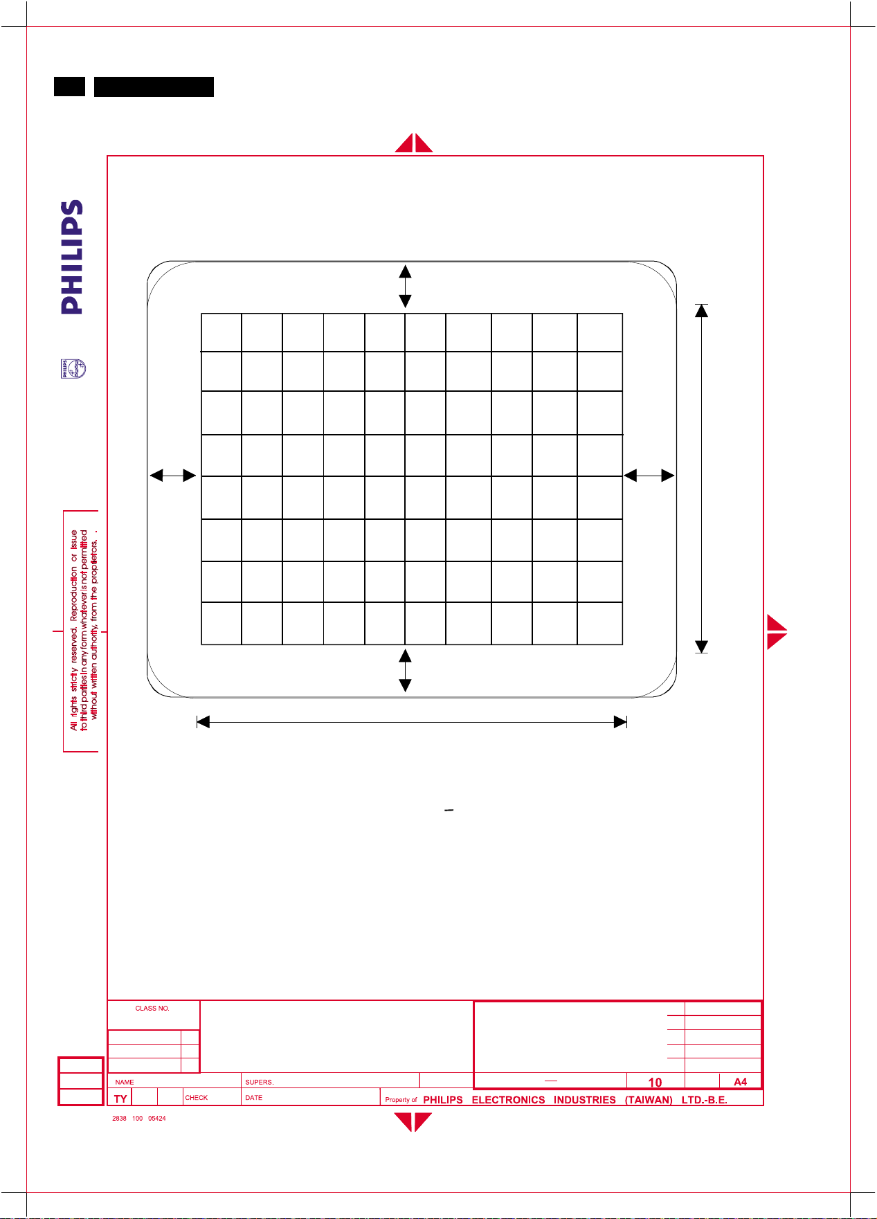
76
http://jdwxzlw.5d6d.com/?fromuser=华盛维修
家电维修资料网,免费下载各种维修资料
9
V20 107E5
Go to cover page
GENERAL PRODUCT SPECIFICATION
C
A
B
230 mm
D
306 mm
|A-B| AND |C-D| < 5 mm
FIG-2 IMAGE CENTERING
17" V20 107E5-70K CMTR
TYPE : 107E51/87
2002-12-13
Roland
BRAND : PHILIPS
29
2002-12-13
8639 000 13531
590
24
Page 77
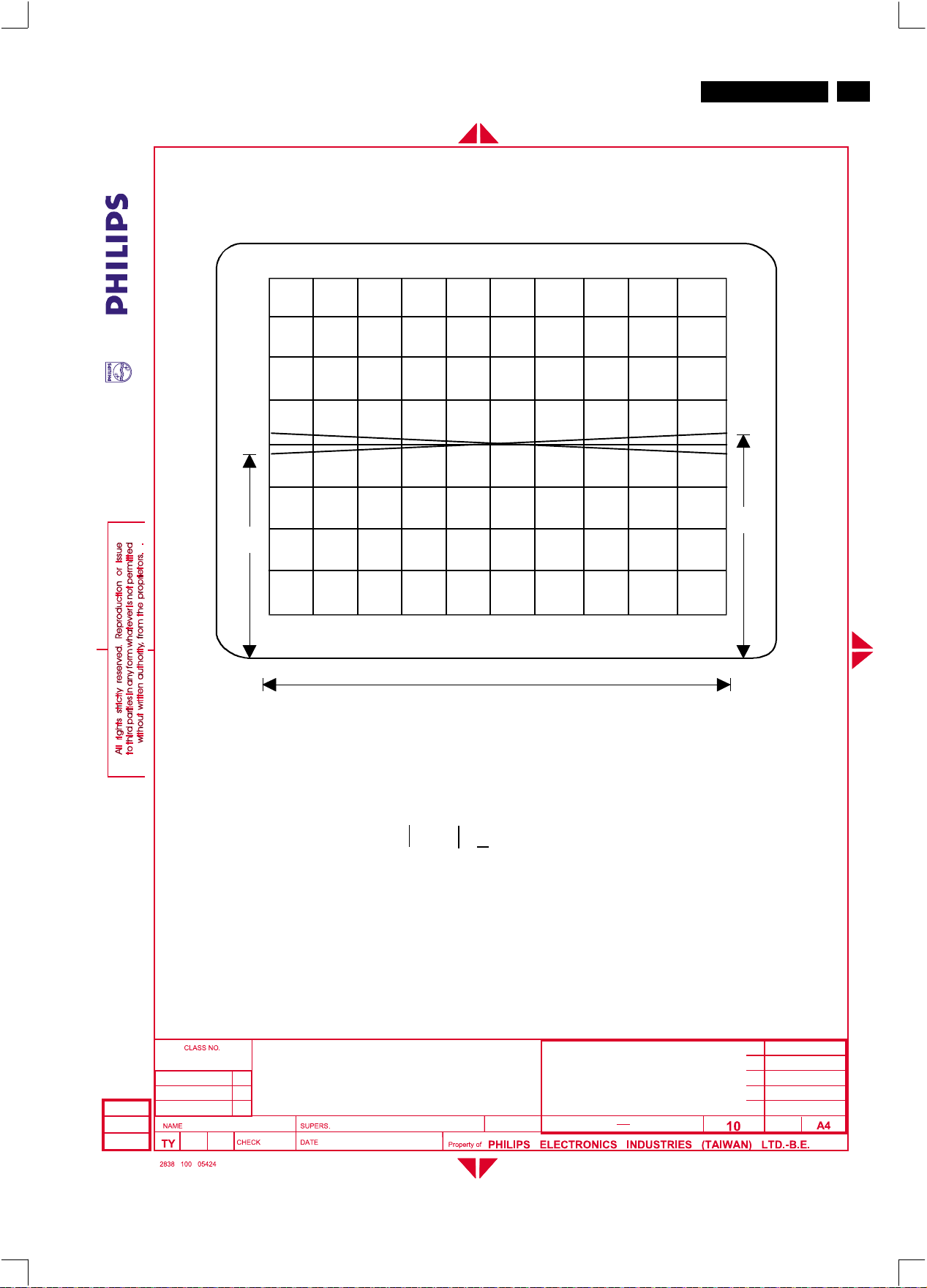
GENERAL PRODUCT SPECIFICATION
http://jdwxzlw.5d6d.com/?fromuser=华盛维修
家电维修资料网,免费下载各种维修资料
V20 107E5
Go to cover page
9
77
B
A
306 mm
A-B < 2 mm
FIG-3 IMAGE ROTATION
17" V20 107E5-70K CMTR
TYPE : 107E51/87
2002-12-13
Roland
BRAND : PHILIPS
29
2002-12-13
8639 000 13531
590
25
Page 78
78
http://jdwxzlw.5d6d.com/?fromuser=华盛维修
家电维修资料网,免费下载各种维修资料
9
V20 107E5
Go to cover page
GENERAL PRODUCT SPECIFICATION
D
A
B
306 mm
A=B=C=D < 2.0 mm
C
230 mm
FIG-4 IMAGE GEOMETRY
17" V20 107E5-70K CMTR
TYPE : 107E51/87
2002-12-13
Roland
BRAND : PHILIPS
29
2002-12-13
8639 000 13531
590
26
Page 79
GENERAL PRODUCT SPECIFICATION
http://jdwxzlw.5d6d.com/?fromuser=华盛维修
家电维修资料网,免费下载各种维修资料
100 mm
V20 107E5
Go to cover page
9
79
ZONE A
ZONE B
306 mm
230 mm
100 mm
FIG-5 CONTRAST AND BRIGHTNESS
MEASUREMENT AREA
17" V20 107E5-70K CMTR
TYPE : 107E51/87
2002-12-13
Roland
BRAND : PHILIPS
29
2002-12-13
8639 000 13531
590
27
Page 80
80
http://jdwxzlw.5d6d.com/?fromuser=华盛维修
家电维修资料网,免费下载各种维修资料
9
V20 107E5
Go to cover page
GENERAL PRODUCT SPECIFICATION
ZONE B
ZONE A
ZONE C
306 mm
230 mm
FIG-6 MISCONVERGENCE
17" V20 107E5-70K CMTR
TYPE : 107E51/87
2002-12-13
Roland
BRAND : PHILIPS
29
2002-12-13
8639 000 13531
590
28
Page 81
GENERAL PRODUCT SPECIFICATION
http://jdwxzlw.5d6d.com/?fromuser=华盛维修
家电维修资料网,免费下载各种维修资料
V20 107E5
Go to cover page
9
81
2002-12-13
Roland
17" V20 107E5-70K CMTR
TYPE : 107E51/87
BRAND : PHILIPS
2002-12-13
Figure 7
Focus check character
8639 000 13531
29
590
29
 Loading...