

Page 1

UM10011_4
Semiconductors
ISP1521 Hi-Speed USB Hub Demo Board
Rev. 04.00 — 17 June 2004 User manual
Document information
Info Content
Keywords
Abstract
ISP1521, hub controller, USB, universal serial bus
This document describes the ISP1521 hub demo board. It also contains
the related schematics, the PCB layout, and the Bill of Material
.
Page 2

Philips Semiconductors
ISP1521 Hi-Speed USB Hub Demo Board
UM10011_4
Revision history
Rev Date Description
4.0 June 2004 Updated the schematics.
3.0 Apr 2004 Updated the following:
• Section 2
• Section 5.7
• Removed Section 5.8 on hybrid power
• Section 6.
1.1 Mar 2003 Updated Section 5.7 and Section 6.
Corrected I
1.0 Nov. 2002 First release.
2
C to I2C-Bus
Contact information
For additional information, please visit: http://www.semiconductors.philips.com/
For sales office addresses, please send an email to: sales.addresses@www.semiconductors.philips.com
User manual Rev. 04.00 — 17 June 2004 2 of 20
© Koninklijke Philips Electronics N.V. 2004. All rights reserved.
Page 3

Philips Semiconductors
This is a legal agreement between you (either an individual or an entity) and Philips Semiconductors. By accepting
this product, you indicate your agreement to the disclaimer specified as follows:
ISP1521 Hi-Speed USB Hub Demo Board
UM10011_4
DISCLAIMER
PRODUCT IS DEEMED ACCEPTED BY RECIPIENT. THE PRODUCT IS PROVIDED “AS IS” WITHOUT
WARRANTY OF ANY KIND. TO THE MAXIMUM EXTENT PERMITTED BY APPLICABLE LAW, PHILIPS
SEMICONDUCTORS FURTHER DISCLAIMS ALL WARRANTIES, INCLUDING WITHOUT LIMITATION ANY
IMPLIED WARRANTIES OF MERCHANT ABILITY, FITNESS FOR A PARTICULAR PURPOSE, AND
NONINFRINGEMENT. THE ENTIRE RISK ARISING OUT OF THE USE OR PERFORMANCE OF THE
PRODUCT AND DOCUMENTATION REMAINS WITH THE RECIPIENT. TO THE MAXIMUM EXTENT
PERMITTED BY APPLICABLE LAW, IN NO EVENT SHALL PHILIPS SEMICONDUCTORS OR ITS SUPPLIERS BE
LIABLE FOR ANY CONSEQUENTIAL, INCIDENTAL, DIRECT, INDIRECT, SPECIAL, PUNITIVE, OR OTHER
DAMAGES WHATSOEVER (INCLUDING, WITHOUT LIMITATION, DAMAGES FOR LOSS OF BUSINESS
PROFITS, BUSINESS INTERRUPTION, LOSS OF BUSINESS INFORMATION, OR OTHER PECUNIARY LOSS)
ARISING OUT OF THIS AGREEMENT OR THE USE OF OR INABILITY TO USE THE PRODUCT, EVEN IF
PHILIPS SEMICONDUCTORS HAS BEEN ADVISED OF THE POSSIBILITY OF SUCH DAMAGES.
User manual Rev. 04.00 — 17 June 2004 3 of 20
© Koninklijke Philips Electronics N.V. 2004. All rights reserved.
Page 4

Philips Semiconductors
ISP1521 Hi-Speed USB Hub Demo Board
UM10011_4
Contents
1. INTRODUCTION...................................................................................................................................................................5
2. ISP1521 HUB DEMO BOARD FEATURES.........................................................................................................................5
3. SYSTEM REQUIREMENTS.....................................................................................................................................................6
4. POWER SUPPLY ADAPTER REQUIREMENTS................................................................................................................6
5. HUB DEMO BOARD DESCRIPTION.................................................................................................................................6
5.1. ISP1521 80-Pin LQFP Package.......................................................................................................................................6
5.2. Port Indicators..................................................................................................................................................................7
5.3. Power LED Indicator ......................................................................................................................................................7
5.4. GoodLink Indicator.........................................................................................................................................................7
5.5. Port Power Switch Transistors.....................................................................................................................................8
5.6. Overcurrent Circuit Detection....................................................................................................................................8
5.7. Power Supply....................................................................................................................................................................8
5.8. I2C-Bus Interface............................................................................................................................................................10
5.9. Other Jumpers................................................................................................................................................................11
5.9.1. J13 (NOOC)..........................................................................................................................................................11
5.9.2. J14 (SUSPEND)......................................................................................................................................................11
6. SCHEMATICS..........................................................................................................................................................................11
7. INSTALLING THE BOARD.................................................................................................................................................19
8. BILL OF MATERIALS FOR THE ISP1521 HU B DEMO BOARD.................................................................................20
9. REFERENCES...........................................................................................................................................................................20
GoodLink and I
2
C-Bus are trademarks of Koninklijke Philips Electronics N.V. Microsoft is a registered trademark of
Microsoft Corp. The names of actual companies and products mentioned herein may b e the trademarks of their
respective owners. All other names, products, and trademarks are the property of their respectiv e owners.
User manual Rev. 04.00 — 17 June 2004 4 of 20
© Koninklijke Philips Electronics N.V. 2004. All rights reserved.
Page 5
Philips Semiconductors
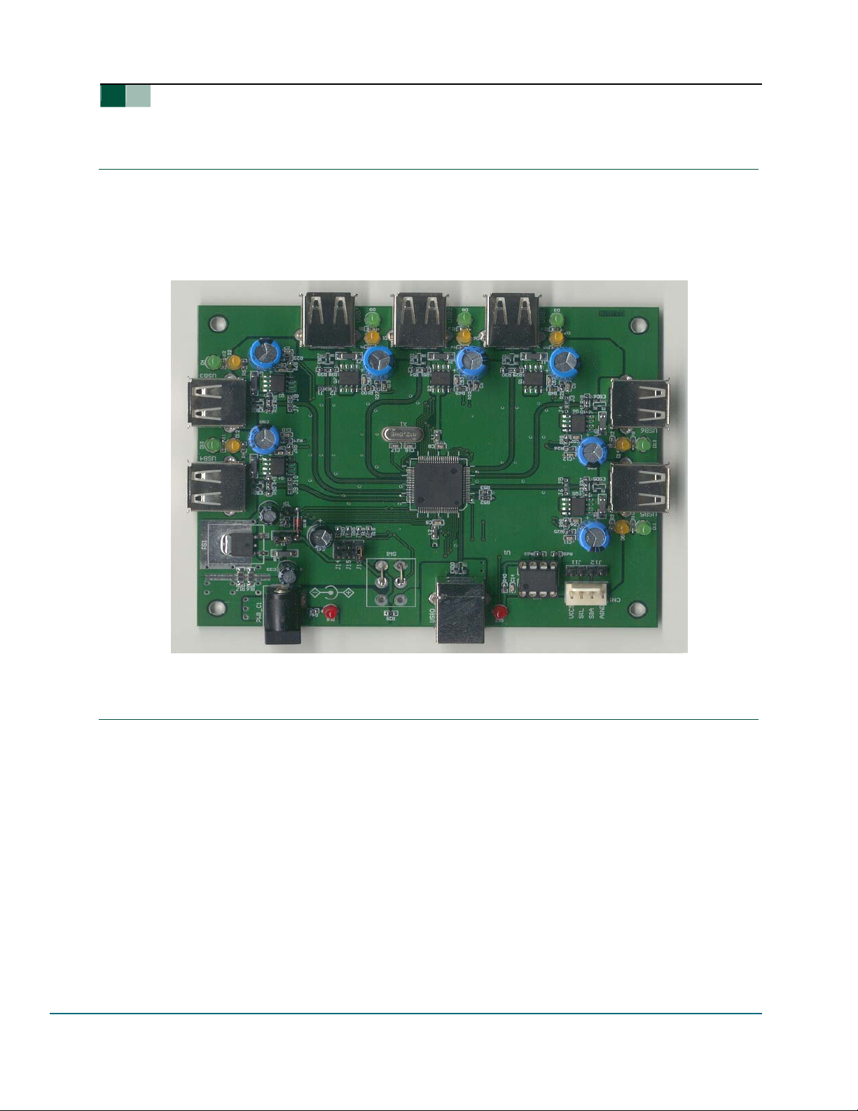
1. Introduction
The ISP1521 is a Hi-Speed Universal Serial Bus (USB) hub IC, with seven downstream facing
ports. The ISP1521 Hub Demo Board is designed to demonstrate the features and functionality
of the ISP1521.
This document describes the ISP1521 Hub Demo Board. It also contains the related schematics,
the PCB layout, and the Bill of Material (BoM).
UM10011_4
ISP1521 Hi-Speed USB Hub Demo Board
Figure 1-1: ISP1521 Hub Demo Board
2. ISP1521 Hub Demo Board Features
• Complies with Universal Serial Bus Specification Rev. 2.0
• Supports self-powered operation
• Configurable number of downstream facing ports (from two to seven)
• Customizable Vendor ID, Product ID and Serial Number (by using an external EEPROM or
an external microcontroller)
• Individual power switching and individual overcurrent protection
TM
• USB traffic indication (GoodLink
• Port status indicators.
User manual Rev. 04.00 — 17 June 2004 5 of 20
LED) on the upstream facing port
© Koninklijke Philips Electronics N.V. 2004. All rights reserved.
Page 6

Philips Semiconductors
3. System Requirements
This hub can be attached to a computer that has a USB or Hi-Speed USB host installed, and
running any of these operating systems:
®
• Windows
98
• Windows Me
• Windows 2000
• Windows XP
®
• MacOS
.
If the hub is plugged into a USB host controller, it will work only as a full-speed hu b.
4. Power Supply Adapter Requirements
Regulated Output: 5.1 VCC ± 5%, 4 A.
Warning: The power plug polarity is (-) at the core and (+) at the outer shield.
UM10011_4
ISP1521 Hi-Speed USB Hub Demo Board
5. Hub Demo Board Description
5.1. ISP1521 80-Pin LQFP Package
The ISP1521 has these port configurations:
• One Hi-Speed USB and USB capable upstream facing port (USB0), and
• Seven Hi-Speed USB and USB capable downstream facing ports (USB1, USB2, USB3, USB4,
USB5, USB6, USB7).
The port numbers are marked near the USB connectors on the silkscreen. The downstream
facing ports USB3, USB4, USB5, USB6 and USB7 can be disabled. Disabling a port will also disable
all higher-number ports. For example, disabling port USB4 will disable ports USB5, USB6 and
USB7 as well. Therefore, apart from port USB7, it is not possib le to selectively disable a port
(For example, only USB5.). By design, ports USB1 and USB2 cannot be disabled.
Table 5-1: Jumper Settings vs. Port Activation
J2, J1 J4, J3 J6, J5 J10, J9 J8, J7 Active Ports
OFF, OFF OFF, OFF OFF, OFF OFF, OFF OFF, OFF USB1 to USB7*
ON, ON OFF, OFF OFF, OFF OFF, OFF OFF, OFF USB1 to USB6
OFF, OFF ON, ON OFF, OFF OFF, OFF OFF, OFF USB1 to USB5
OFF, OFF OFF, OFF ON, ON OFF, OFF OFF, OFF USB1 to USB4
OFF, OFF OFF, OFF OFF, OFF ON, ON OFF, OFF USB1 to USB3
OFF, OFF OFF, OFF OFF, OFF OFF, OFF ON, ON USB1 to USB2
*—Default settings.
These jumpers are set to “ON” by placing a solder joint on the provided footprints.
User manual Rev. 04.00 — 17 June 2004 6 of 20
© Koninklijke Philips Electronics N.V. 2004. All rights reserved.
Page 7

Philips Semiconductors
J
joints to disable a
5.2. Port Indicators
The D1, D2, D3, D4, D5, D6, D7, D8, D9, D10, D11, D12, D13 and D14 are port indicators.
Conforming to the Universal Serial Bus Specification Rev. 2.0, each downstream facing port has two
port indicators—green and amber—placed to its right.
UM10011_4
ISP1521 Hi-Speed USB Hub Demo Board
1 and J2 solder
port
If the green LED is ON, it means the device connected to the port was successfully enumerated
and is functional.
If the amber LED is ON, it means there is an overcurrent condition.
Custom software applications or drivers may flash these LEDs to attract user attention.
5.3. Power LED Indicator
When power is supplied to the board, LED D16 lights up (red).
5.4. GoodLink Indicator
A Philips GoodLinkTM LED D15 (red) is located near the upstream facing port. This LED blinks on
every successful USB transactions.
User manual Rev. 04.00 — 17 June 2004 7 of 20
© Koninklijke Philips Electronics N.V. 2004. All rights reserved.
Page 8

Philips Semiconductors
5.5. Port Power Switch Transistors
The hub switches on or off the bus power to each downstream facing port through a low ohm ic
PMOS transistor.
5.6. Overcurrent Circuit Detection
The integrated analog overcurrent detection circuit of the ISP1521 senses the voltage drop
across the power switch. When the port draws too much current, the voltage drop across the
power switch exceeds the trip voltage threshold. The overcurrent circuit detects this and
automatically switches off the power switch. More information on choosing the switch and
trimming the overcurrent detection voltage can be found in the ISP1521 Hi-Speed Universal Serial
Bus hub controller data sheet.
UM10011_4
ISP1521 Hi-Speed USB Hub Demo Board
5.7. Power Supply
To power up the hub, plug the power supply into the power supply socket (PWR _C1).
Jumper J15 will set the powering mode in the hub’s descr iptors as self-po wered hub; see
Table 5-2.
Table 5-2: Setting the Power Mode Using J15
J15 Power Mode Logic State
OFF Self* 1 (HIGH)
*—Default settings.
J15
User manual Rev. 04.00 — 17 June 2004 8 of 20
© Koninklijke Philips Electronics N.V. 2004. All rights reserved.
Page 9

Philips Semiconductors
UM10011_4
ISP1521 Hi-Speed USB Hub Demo Board
Figure 5-1: Windows Reporting of the Bus-Powered Mode
User manual Rev. 04.00 — 17 June 2004 9 of 20
© Koninklijke Philips Electronics N.V. 2004. All rights reserved.
Page 10

Philips Semiconductors
UM10011_4
ISP1521 Hi-Speed USB Hub Demo Board
Figure 5-2: Windows Reporting of the Self-Powered Mode
5.8. I2C-Bus Interface
The ISP1521 can use either its USB descriptors from the internal ROM, or from an external I2C-
TM
EEPROM or microcontroller. Mode selection is done through jumpers J11and J12 (see
Bus
Table 5-3).
Table 5-3: Mode Selection Using J11 and J12
User manual Rev. 04.00 — 17 June 2004 10 of 20
J11 J12 Mode SCL SDA
ON ON Internal ROM LOW LOW
OFF OFF I2C-Bus EEPROM* HIGH HIGH
*—Default settings.
2
An external I
C-Bus controller acting as a master can also be used to update hub descriptors
through the CN1 connector.
2
Note: The I
C-Bus external EEPROM cannot be programmed on-board.
© Koninklijke Philips Electronics N.V. 2004. All rights reserved.
Page 11

Philips Semiconductors
5.9. Other Jumpers
5.9.1. J13 (NOOC)
This jumper will set the OC capabilities in the hub’s descriptors (see Table 5-4).
Table 5-4: Overcurrent Support Selection Using J11 and J12
J13 NOOC Logic State
OFF No overcurrent support 1 (HIGH)
ON Overcurrent support* 0 (LOW)
*—Default settings.
Note: this jumper is for setting the hub’s descriptor only. To inhibit the overcurrent detection,
the OC pins must be tied to V
(5 V)
CC
UM10011_4
ISP1521 Hi-Speed USB Hub Demo Board
5.9.2. J14 (SUSPEND)
This jumper is provided for debugging purposes. Logic 1 on the SUSPEND signal indicates that
the hub is in the suspend mode. In the default setting jumper J14 is used (pulled down to GND).
Table 5-5: J14 Mode Setting
6. Schematics
J14 Mode
OFF Debugging purpose
ON Normal mode (default)
User manual Rev. 04.00 — 17 June 2004 11 of 20
© Koninklijke Philips Electronics N.V. 2004. All rights reserved.
Page 12

C85
150u F
C90
150u F
C95
150u F
8
7
6
5
4
3
VBU S
1
4
REF2
3
VBU S1
4
REF2
3
1
5
REF1
ESD 0
CHASSIS
I/O12I/O2
PSR05
L11
1
1
5
REF1
ESD1
CHASSIS
I/O12I/O2
PSR05
PIGR N1
PIGR N2
PIGR N3
PIGR N4
PIGR N5
PIGR N6
GRND8
GRND1 1
GRND3
GRND1 0
GRND4
330RR12
330RR9
330RR13
330RR10
330RR14
330RR11
0.01 uFC2
1nFC1
VBU S2
USB_U P
USB_D OWN
PIABR7
AMBRD14
330RR1
4
REF2
3
1nFC4
VBU S3
4
REF2
3
AMBRD1
REDD1 5
330RR40
6
4
GND
VBU S
D-2D+
CHASSIS
USB0
3
DM0
DP0
C31
150u F
0. 01uFC3
0. 1uF
C25
4
6
GND
VBU S
D-2D+
CHASSIS
USB1
3
15KR30
15KR29
DM1
DP1
PIGR N7
PIABR1
PIABR2
PIABR3
PIABR4
PIABR5
PIABR6
AMBRD2
GRND1 3
AMBRD6
AMBRD5
AMBRD7
AMBRD12
GRND9
330RR4
330RR8
330RR5
330RR2
330RR6
330RR3
330RR7
L21
1
1
5
REF1
ESD 2
CHASSIS
I/O12I/O2
PSR05
L31
1
1
5
REF1
ESD3
CHASSIS
I/O12I/O2
PSR05
J7
J8
J9
V3. 3REG
J10
78
66
75
77
62
64
68
73
65
74
76
61
63
67
72
C36
VBU S
D-2D+
3
DM2
DP2
C30
VBU S
D-2D+
3
DP3
DM3
DP0
DM0
DM0
DP0
4
3
DP0
DM0
HUB GL
PIABR7
PIABR6
PIABR5
PIABR4
PIABR3
PIABR2
PIABR1
PIGRN7
PIGRN6
PIGRN5
PIGRN4
PIGRN3
PIGRN2
PIGRN1
0.01 uFC83
0.1uF
6
4
GND
CHASSIS
USB2
15KR54
15KR51
C70
150u F
0. 01uFC68
0. 1uF
4
6
GND
CHASSIS
USB3
15KR32
15KR31
DP1
DM1
DM2
DM1
DM2
DP1
20
45
19
DP1
DM2
DM1
VCC311VCC313VCC317VCC350VCC352VCC3
V3.3 (13)
V3.3 (17)
V3.3 (50)
V3.3 (52)
V3.3 (11)
1nFC84
VBU S4
4
REF2
USB_D OWN
3
1nFC69
VBU S5
4
REF2
USB_D OWN
3
DP2
DP3
DM3
DM4
DM3
DM4
DP2
DP3
55
46
58
54
DP3
DP2
DM4
DM3
VCC531VCC569VCC470VCC4
30
56
VCC5( 31)
VAUX( 70)
V3.3 (56)
VCC5( 69)
VAUX( 30)
L41
1
1
5
REF1
ESD 4
CHASSIS
I/O12I/O2
PSR05
L51
1
1
5
REF1
ESD5
CHASSIS
I/O12I/O2
PSR05
DP4
DP5
DM5
DM6
DP6
DP5
DP4
DM6
DM5
16
10
59
15
9
DP5
DP4
DM6
DM5
U1
ISP 1521_ LQFP 80
23
OC1
OC2
OC3
OC4
OC5
OC1
OC2
OC3
OC4
0.01 uFC88
1nFC89
0.1uF
C37
6
4
GND
VBU S
D-2D+
CHASSIS
USB4
3
15KR50
15KR49
DM4
DP4
C75
150u F
0. 01uFC73
0. 1uF
C34
4
6
GND
VBU S
D-2D+
CHASSIS
USB5
3
15KR34
15KR33
DM5
DP7
DP6
DM7
DP7
DM7 DP 5
49
48
DP7
DP6
DM7
PSW2
PSW1
PSW3
OC6
OC5
PSW4
OC7
OC6
OC7
PSW1
PSW2
PSW3
VBU S6
4
REF2
USB_D OWN
3
1nFC74
VBU S7
4
REF2
USB_D OWN
3
J6
J5
J4
J3
J2
V3. 3REG
J1
43
XTAL142XTAL2
PSW7
PSW626PSW528PSW433PSW335PSW239PSW124OC736OC625OC527OC432OC334OC238OC1
RPU5RREF
7
37
PSW7
PSW6
PSW5
1K5, 1%
R52
PSW7
PSW6
PSW4
PSW5
L61
1
1
5
REF1
ESD 6
CHASSIS
I/O12I/O2
PSR05
L71
1
1
5
REF1
ESD7
CHASSIS
I/O12I/O2
PSR05
79
80
AGND
AGND
SCL
SDA
AGND
AGND
AGND
AGND
AGND
AGND
AGND
AGND
AGND
DGND
DGND
NOOC
ADOC
SP/BP
HP
SUSPEND
RESET
VBU S
VBU S
D-2D+
DM6DM7
D-2D+
57
53
51
47
44
18
14
12
8
6
2
71
29
60
41
22
21
1
40
C38
3
DP6
C80
C35
3
DP7
12K, 1%R53
V3. 3REG
0.1uF
6
4
GND
CHASSIS
15KR48
15KR47
150u F
0. 1uF
4
6
GND
CHASSIS
15KR39
15KR38
0.01 uFC93
USB_D OWN
USB6
0. 01uFC78
USB_D OWN
USB7
VCC5
0.1u FC14
NOOC
ADOC
SP/BP
HP
SUSPEND
NCR2 0
10KR19
10KR18
10KR55
1nFC94
ISP1521 EVAL BOARD
Title
1nFC79
22pF
C18
X1
12M Hz
22pF
C17
No EEPROM used: J11 & J12
EEPROM used: No J11 & J12
2K2
R65
R63
2K2
7
8
WP
VCC
A01A12A23GND
SUSPEND
5
6
SCL
4
SDA
PCF8582
U2
4
10K
R43
V3.3R EG
1N41 48
D18
NOOC
ADOC
SP/BP
J12
J11
123
SIP _4P
CN1
0.1u F
C16
TP
J14(By default)
J14
J13
J15
8
7
Numb er Revis ionSize
A3
Date: 2004-03-24 Sheet of
Fil e: C :\My N oteBo ok Raw\ ..\IS P1521 _Up date. SchDrawn By:
6
5
4
3
2
1
VCC5
Qrp u NPN
V3. 3REG
5K6
RVbus
VBU S
A A
B B
C C
D D
2
1
Page 13

4
0. 1uF
C24
V3 .3(5 6)
22 uF
C61
V3 .3REG
J1 6
3
Vo ut
Vs s
1
XC6 206P 302
PS1
Vi n
2
SW1
3
SW1
5 6
HP
VCC 5 VBUS
3 4
1 2
0R
R28
L5
33 0R
R46
123
1u F
C33
0RR16
0RR17
RED
D1 6
L4
V3 .3REG
L3
V3 .3REG
L2
VCC5
L1
VCC 5
0. 1uF
C32
VA UX(70)
0. 1uF
C15
VA UX(30)
0. 1uF
C9
VCC 5(69)
0. 1uF
C8
VCC5(31)
L1 2
V3 .3REG
0. 1uF
C23
V3 .3(5 2)
L1 0
V3 .3REG
0. 1uF
C22
V3 .3(5 0)
L9
V3 .3REG
0. 1uF
C21
V3 .3(1 7)
L8
V3 .3REG
0. 1uF
C20
V3 .3(1 3)
L7
V3 .3REG
0. 1uF
C19
V3 .3(1 1)
L6
V3 .3REG
Nu mbe r Re visio nSize
POW E R CI R C UI T
Ti tle
4
A4
Date: 2004-03-24 Sheet of
File: C:\My NoteBook Raw\..\1521updatePWR-CCT-A.SchDra wn By:
3
PWR_C1
2
0. 1uF
C5
OC1
VBUS 1
10 K
R21
785
6
ND S943 5A
Q1
4
1
2
3
0. 1uF
C52
1
VCC5
47 K
R68
PSW1
VBUS 2
1
785
6
2
3
OC2
R22
DC_ IN
2
0. 1uF
C6
10 K
0. 1uF
C53
VBUS 3
785
ND S943 5A
Q2
4
1
2
47 K
R69
PSW2
0. 1uF
C7
OC3
10 K
R23
6
3
0. 1uF
C54
VBUS 4
785
ND S943 5A
Q3
4
1
2
47 K
R70
PSW3
0. 1uF
C10
OC4
10 K
R24
6
3
0. 1uF
C55
VBUS 5
785
ND S943 5A
Q4
4
1
2
47 K
R97
PSW4
0. 1uF
C11
OC5
10 K
R25
6
3
0. 1uF
C56
VBUS 6
785
ND S943 5A
Q5
4
1
2
47 K
R98
PSW5
0. 1uF
C12
OC6
10 K
R26
6
3
0. 1uF
C57
VBUS 7
785
ND S943 5A
Q6
4
1
2
47 K
R99
PSW6
0. 1uF
C13
OC7
10 K
R27
6
ND S943 5A
Q7
4
3
0. 1uF
C58
47 K
R100
PSW7
1
A A
B B
C C
D D
Page 14

Philips Semiconductors
UM10011_4
ISP1521 Hi-Speed USB Hub Demo Board
Component Placement
User manual Rev. 04.00 — 17 June 2004 14 of 20
© Koninklijke Philips Electronics N.V. 2004. All rights reserved.
Page 15

Philips Semiconductors
UM10011_4
ISP1521 Hi-Speed USB Hub Demo Board
Layer 1: Top Routing
User manual Rev. 04.00 — 17 June 2004 15 of 20
© Koninklijke Philips Electronics N.V. 2004. All rights reserved.
Page 16

Philips Semiconductors
UM10011_4
ISP1521 Hi-Speed USB Hub Demo Board
Layer 2: Ground Planes
User manual Rev. 04.00 — 17 June 2004 16 of 20
© Koninklijke Philips Electronics N.V. 2004. All rights reserved.
Page 17

Philips Semiconductors
UM10011_4
ISP1521 Hi-Speed USB Hub Demo Board
Layer3: Power Planes
User manual Rev. 04.00 — 17 June 2004 17 of 20
© Koninklijke Philips Electronics N.V. 2004. All rights reserved.
Page 18

Philips Semiconductors
UM10011_4
ISP1521 Hi-Speed USB Hub Demo Board
Layer 4: Bottom Routing
User manual Rev. 04.00 — 17 June 2004 18 of 20
© Koninklijke Philips Electronics N.V. 2004. All rights reserved.
Page 19

Philips Semiconductors
7. Installing the Board
Assuming that you have already installed the USB host adapter (including drivers) on a c omputer
running Windows, installing the hub is fairly simple.
1. Plug in power from the power supply to the hub. The power supply must meet the
requirements specified in Section 4.
2. Plug a USB cable in the USB0 port, and connect the other end of the cable to the USB host.
After a while the GoodLink LED (D15) will start to blink. This means that the enumeration
process has successfully completed and the hub is now ready for use.
You can check the driver installation in the Device Manager window. To check whether the
hub is correctly installed in high-speed, choose the View-Devices by connection command
in the Device Manager window.
UM10011_4
ISP1521 Hi-Speed USB Hub Demo Board
3. Plug in devices to the downstream facing ports. After these devices are properly
enumerated, the green LEDs will turn ON.
User manual Rev. 04.00 — 17 June 2004 19 of 20
© Koninklijke Philips Electronics N.V. 2004. All rights reserved.
Page 20

Philips Semiconductors
ISP1521 Hi-Speed USB Hub Demo Board
8. Bill of Materials for the ISP1521 Hub Demo Board
Part Type Footprint Quantity Designator
0.01 F 0603C 8 C2, C3, C68, C73, C78, C83, C88, C93
0.1 F 0603C 32 C5, C6, C7, C8, C9, C10, C11, C12, C13, C14, C15, C19,
C20, C21, C22, C23, C24, C25, C30, C32, C34, C35, C36,
C37, C38, C52, C53, C54, C55, C56, C57, C58
0 Ώ
0 Ώ
0 Ώ
100 F/10 V REC2-25 1 C61
10 kΏ
10 F/10 V REC1-2 1 C33
10 F REC1-2 1 C16
12 kΏ, 1%
12 MHz, low profile XTAL7 1 X1
150 F/10 V REC15-3 7 C31, C70, C75, C80, C85, C90, C95
15 kΏ
1.5 kΏ, 1%
1N4148 DIODE0.3 1 D18
1 nF 0603C 8 C1, C4, C69, C74, C79, C84, C89, C94
22 pF 0603C 2 C17, C18
2.2 kΏ
330 Ώ
47 kΏ
AMBER LED3 7 D1, D2, D5, D6, D7, D12, D14
BLM21AG221SN1 0805G 10 L1, L2, L3, L4, L6, L7, L8, L9, L10, L12
BLM41P600S 1206CUST 8 L5, L11, L21, L31, L41, L51, L61, L71
DC_IN DC-JACK2 1 PWR_C1
GREEN LED3 7 D3, D4, D8, D9, D10, D11, D13
ISP1521 LQFP80-0.5 1 U1
JUMPER 0603 4 J1, J10, J2, J3, J4, J5, J6, J7, J8, J9
JUMPER RAD0.1 6 J11, J12, J13, J14, J15, J16
BA033-3.3 TO-263/D2PAK 1 PS1
USB_UP USB-TYPEB 1 USB0
NDS9435A SO-8 7 Q1, Q2, Q3, Q4, Q5, Q6, Q7
PCF8582 DIP8 1 U2
PSR05 SOT-143 8 ESD0, ESD1, ESD2, ESD3, ESD4, ESD5, ESD6, ESD7
RED LED3 2 D15, D16
SIP_4P PS24254-4 1 CN1
SW1 TOGGSW2 1 SW1
Test Point TP 1 TP1
USB_DOWN USB-TYPEA 7 USB1, USB2, USB3, USB4, USB5, USB6, USB7
0603R 1 R55
0805GR 1 R28
1206G 2 R16, R17
0603R 11
0603R 1
0603R
0603R 1
0603R 2
0603R
0603R 7
14
16
R18, R19, R20, R21, R22, R23, R24, R25, R26, R27, R43, R44
R53
R29, R30, R31, R32, R33, R34, R38, R39, R47, R48, R49, R50,
R51, R54
R52
R63, R65
R1, R2, R3, R4, R5, R6, R7, R8, R9, R10, R11, R12, R13, R14,
R40, R46
R68, R69, R70, R97, R98, R99, R100
UM10011_4
9. References
• Universal Serial Bus Specification Rev. 2.0 (http://www.usb.org/)
• ISP1521 Hi-Speed Universal Serial Bus hub controller data sheet.
User manual Rev. 04.00 — 17 June 2004 20 of 20
© Koninklijke Philips Electronics N.V. 2004. All rights reserved.
 Loading...