

Philips TEA1104T-N2, TEA1104-N2, TEA1104-N1 Datasheet

DATA SH EET
Objective specification
File under Integrated Circuits, IC03
1996 Feb 26
INTEGRATED CIRCUITS
TEA1104; TEA1104T
Cost effective battery monitor and
fast charge IC for NiCd and NiMH
chargers

1996 Feb 26 2
Philips Semiconductors Objective specification
Cost effective battery monitor and fast
charge IC for NiCd and NiMH chargers
TEA1104; TEA1104T
FEATURES
• Accurate detection of fully charged batteries by
currentless peak voltage sensing
• Switch-over from fast to safe trickle charge current at
battery full detection
• Fast charge termination back-up by maximum time and
maximum temperature detection
• Several trickle charge drive possibilities for mains
isolated and non-mains isolated systems
• Battery checking to protect against short-circuited and
open batteries
• Battery monitor allows recharging of different battery
packs in the same charger
• Dual LED indicator provision
• External regulator not required because of large input
voltage range
• Few low cost external components required.
APPLICATIONS
• Portable telephone
• Portable computer
• Portable audio
• Portable video.
GENERAL DESCRIPTION
The TEA1104 is manufactured in a BiCMOS process
intended to be used as a battery monitor circuit in charge
systems for NiCd and NiMH batteries. It is especially
designed for cost effective compact consumer
applications.
The circuit is able to detect fully charged batteries by
currentless battery voltage sensing. Several output drive
functions are available to control the (reduced) trickle
charge current to keep the batteries full with maximum life
expectations.
The battery full detection is backed up by two independent
mechanisms to make the system fail safe; maximum time
and maximum temperature.
QUICK REFERENCE DATA
ORDERING INFORMATION
SYMBOL PARAMETER CONDITIONS MIN. TYP. MAX. UNIT
V
P
supply voltage 5.45 − 11.5 V
I
P
supply current outputs off −−3mA
V
bat
voltage range of battery full detection 0.81 − 3.6 V
∆V
bat/Vbat
voltage peak detection level with
respect to top value
− 0.25 − %
I
bat
battery monitor input current −−1nA
V
bat(l)
battery voltage protection low − 0.81 0.91 V
V
bat(h)
battery voltage protection high 3.5 3.6 − V
f
osc
oscillator frequency 10 − 100 kHz
TYPE
NUMBER
PACKAGE
NAME DESCRIPTION VERSION
TEA1104 DIP8 plastic dual in-line package; 8 leads (300 mil) SOT97-1
TEA1104T SO8 plastic small outline package; 8 leads; body width 3.9 mm SOT96-1
1996 Feb 26 3
Philips Semiconductors Objective specification
Cost effective battery monitor and fast
charge IC for NiCd and NiMH chargers
TEA1104; TEA1104T
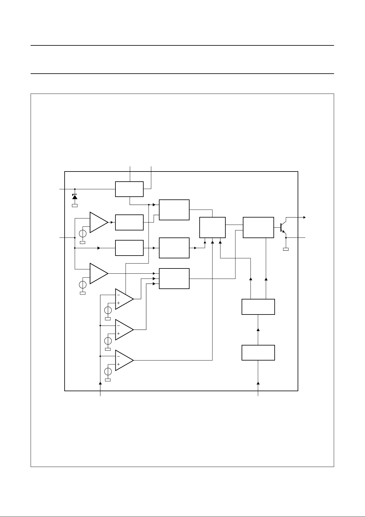
BLOCK DIAGRAM
handbook, full pagewidth
MGE354
SAMPLE-
AND-HOLD
FILTER
BATTERY
FULL
DETECTOR
OR
OR
SUPPLY
MODE
LATCH
OSCILLATOR
TIMER
fast
trickle
CONTROL
battery high
protection
battery low
protection
T
max
T
min
T
cut-off
trickle
TO
4
6
2
7
1
8
5
3
R
ref
V
S
V
P
V
bat
NTC OSC
LED
GND
POR
TEA1104
TEA1104T
Fig.1 Block diagram.

1996 Feb 26 4
Philips Semiconductors Objective specification
Cost effective battery monitor and fast
charge IC for NiCd and NiMH chargers
TEA1104; TEA1104T
PINNING
SYMBOL PIN DESCRIPTION
GND 1 ground
NTC 2 negative temperature coefficient
resistor input
V
S
3 stabilized supply voltage
V
bat
4 battery voltage sensing
R
ref
5 reference resistor
V
P
6 positive supply voltage
OSC 7 oscillator input
LED 8 LED output
Fig.2 Pin configuration.
handbook, halfpage
1
2
3
4
8
7
6
5
MGE353
TEA1104
LED
OSCNTC
V
P
R
ref
V
bat
V
s
GND
INTRODUCTION
The operation of the TEA1104; TEA1104T is explained
with the aid of the application diagram illustrated in Fig.7.
An application note (AN95085) is available describing the
versatility of the TEA1104; TEA1104T.
An external power current source charges the batteries via
an electronic switch which is controlled by the TEA1104.
The TEA1104 monitors the battery voltage. Fully charged
batteries are detected when the battery voltage peaks. In
fact, a voltage drop of 0.25% with respect to the top value
is detected. Fast charging is initiated at ‘power on’ or at
‘replaced batteries’. The switch is continuously on,
providing that all protection levels are met. At battery full
detection, the charge current is duty cycled to reduce the
average charge current to a lower level, keeping the
batteries fully charged but at he same time assuring long
battery life. In Fig.3 the battery voltage during fast charge
is plotted.
FUNCTIONAL DESCRIPTION
A block diagram of the TEA1104; TEA1104T is illustrated
in Fig.1
Mode latch
The Mode latch determines if the system is in the fast or in
the slow charge mode.
• Fast charge is active at:
– power switch-on and battery connected
– temperature between minimum and maximum value
– battery insert
• Trickle charge is active if:
– battery full is detected
– maximum time is exceeded
– maximum cut-off temperature is exceeded after the
initial phase.
Supply block
For correct start-up, the IC supply current is limited to
35 µA (typ.) until the start-up voltage of 6.4 V is reached
(standby mode). Thereafter, the operating supply voltage
V
P
has to be within the window of 5.45 to 11.5 V, meaning
that there is no need for an external voltage regulator to
supply the IC.
The supply block delivers the following outputs:
• With the help of an external resistor (pin R
ref
), a
reference current is obtained which defines the
accuracy of all IC timing characteristics
• Externally available 4.25 V stabilized voltage source
(V
source
). This source is used internally to supply a large
part of the circuit and can be used to set the NTC biasing
and to supply other external circuitry with a maximum
current of 1 mA. Protection information is provided via
VS, to design a dual LED indicator
• Power-on reset pulse resets all digital circuitry after a
start or restart, due to an interrupted VS.

1996 Feb 26 5
Philips Semiconductors Objective specification
Cost effective battery monitor and fast
charge IC for NiCd and NiMH chargers
TEA1104; TEA1104T
Open battery protection
When the rechargeable battery is removed, the output
voltage V
bat
will rise to a high level. The ‘open battery
protection’ block will detect this voltage and the charge
current will be switched off. A digital filter prevents false
open battery protection. The open battery signal
(V
bat
> 3.6 V) must be present for a duration of at least
4 clock pulses.
Battery monitor
One or two cell packs can be connected directly to V
bat
(battery connection) without an external resistor divider. At
larger cell packs the battery voltage must be scaled down
to a voltage range of 0.81 to 3.6 V. It is also possible to
take a tap on the chain of batteries. Battery full is
recognized by voltage peak detection (V
peak
), meaning a
decrease of 0.25% (typ.) with respect to the top value.
Keeping in mind a battery voltage range of 0.81 to 3.6 V
and an accuracy of 10% at V
bat
= 2.4 V for battery full
detection, means that the internal ADC has to be 13 bits.
Several filters are included to prevent false full detection.
The series resistance of the battery and battery connection
can cause battery voltage fluctuations and therefore it is
necessary to stop the charging before sensing; this is
called the ‘inhibit time’. This will be performed
automatically via the regulation output pin LED. The
charging is stopped for ten oscillator periods at the end of
which sampling is performed. The battery voltage will now
be sensed in a currentless way.
Timer/oscillator
The oscillator has a sawtooth shape.
The period time is defined by: t
osc
=K×R
ref
× C
osc
The oscillator frequency is used in the timer block. In this
block several important signals are created.
• Time-out for protecting the fast charge process in time.
Time-out is normally chosen to be 25% longer than the
associated fast charge time. So for a one hour charge
time, time-out = 1.25 hours. The relationship with the
oscillator period time is:
– Time-out = 2 exp28 × t
osc
• The duty factor in the trickle charge mode: The duty
factor is fixed to1⁄40, meaning that the average:
–I
trickle
=1⁄40× I
fast
–ton=3⁄4× 2 exp9 × t
osc
–t
off
= 2 exp14 × t
osc
.
• The battery voltage is sensed each ‘cycle time’. The
cycle time is defined as:
–T
cycle
= 2 exp16 × t
osc
• The ‘inhibit time’ is the time that the charger current is
disabled, after which the battery voltage is sensed in a
currentless way.
–t
inhibit
=10×t
osc
Battery sampling takes one oscillator period for each
cycle interval.
–t
sample=tosc
• The ‘disable time’ is present to correct start-up with flat
or polarized batteries. During the disable time, the
battery full detection is not active.
–t
disable
= 2 exp −5 × time-out
The timer is reset by battery full detection, but is on hold
during the temperature and battery-low protection modes.
Temperature protection block
Temperature sensing is achieved by using a cheap
thermistor. Two temperature windows are built in:
• If the temperature at power-on reset is above the
maximum temperature protection level, the trickle
charge current is active. The same applies for
temperatures below the minimum temperature. Fast
charging starts when the temperature is in between the
minimum and the maximum temperature levels.
• If the temperature is between the maximum and
minimum temperature at power-on reset, the fast charge
current level is active. If the temperature sinks below the
minimum temperature level, again the trickle charge
level is active. At rising temperature, the fast charge
current is latched off at the ‘cut off’ temperature level.
To avoid switching on and off with temperature, a
hysteresis is built in for low temperature level. If the
temperature protection is not necessary, pin ‘Negative
Temperature Coefficient resistor’ (NTC) must be
connected to pin R
ref
.
Battery low protections
When the battery voltage is less than 0.81 V, the circuit
assumes that there are short circuited batteries and the
charge current is reduced to the trickle charge level. If the
batteries are flat, the trickle charge current is able to raise
the battery voltage within an acceptable period of time,
after which fast charging starts.
 Loading...