

Philips TEA1103-N2, TEA1103-N1, TEA1103TS-N2, TEA1103T-N2, TEA1103T-N1 Datasheet

DATA SH EET
Preliminary specification
Supersedes data of 1997 Oct 09
File under Integrated Circuits, IC03
1999 Jan 27
INTEGRATED CIRCUITS
TEA1103; TEA1103T;
TEA1103TS
Fast charge ICs for NiCd and NiMH
batteries

1999 Jan 27 2
Philips Semiconductors Preliminary specification
Fast charge ICs for NiCd and NiMH
batteries
TEA1103; TEA1103T;
TEA1103TS
FEATURES
• Safe and fast charging of Nickel Cadmium (NiCd) and
Nickel Metal Hydride (NiMH) batteries
• Pin compatible with the TEA1102x, fast charge ICs for
LiIon, SLA, NiCd and NiMH batteries
• Three charge states for NiCd or NiMH; fast, top-off and
trickle or voltage regulation (optional)
• Adjustable fast charge current [0.5CA to 5CA nominal
(CA = Capacity Amperes)]
• DC top-off and pulsating trickle charge current (NiCd
and NiMH)
• Temperature dependent ∆T/∆t battery full detection
• Automatic switch-over to accurate peak voltage
detection (−
1
⁄4%) if no NTC is applied
• Possibility to use both ∆T/∆t and peak voltage detection
as main fast charge termination
• Support of inhibit during all charging states
• Manual refresh with regulated adjustable discharge
current (NiCd and NiMH)
• Voltage regulation in the event of no battery
• Support of battery voltage based charge indication and
buzzer signalling at battery insertion, end of refresh and
at full detection
• Single, dual and separate LED outputs for indication of
charge status state
• Minimum and maximum temperature protection
• Time-out protection
• Short-circuit battery voltage protection
• Can be applied with few low-cost external components.
GENERAL DESCRIPTION
The TEA1103x are fast charge ICs which are able to fast
charge NiCd and NiMH batteries.
The main fast charge termination for NiCd and NiMH
batteries are ∆T/∆t and peak voltage detection, both of
which are well proven techniques. The TEA1103x
automatically switches over from ∆T/∆t to peak voltage
detection if the thermistor fails or is not present. The ∆T/∆t
detection sensitivity is temperature dependent, thus
avoiding false charge termination. Three charge states
can be distinguished; fast, top-off and trickle.
Several LEDs, as well as a buzzer, can be connected to
the TEA1103x for indicating battery insertion, charge
states, battery full condition and protection mode.
The TEA1103x are contained in a 20-pin package and are
manufactured in a BiCMOS process, essentially for
integrating the complex mix of requirements in a single
chip solution. Only a few external low cost components are
required in order to build a state of the art charger.
The TEA1103x are pin compatible with the TEA1102x, fast
charge ICs for LiIon, SLA, NiCd and NiMH batteries.
ORDERING INFORMATION
TYPE
NUMBER
PACKAGE
NAME DESCRIPTION VERSION
TEA1103 DIP20 plastic dual in-line package; 20 leads (300 mil) SOT146-1
TEA1103T SO20 plastic small outline package; 20 leads; body width 7.5 mm SOT163-1
TEA1103TS SSOP20 plastic shrink small outline package; 20 leads; body width 5.3 mm SOT339-1

1999 Jan 27 3
Philips Semiconductors Preliminary specification
Fast charge ICs for NiCd and NiMH
batteries
TEA1103; TEA1103T;
TEA1103TS
QUICK REFERENCE DATA
SYMBOL PARAMETER CONDITIONS MIN. TYP. MAX. UNIT
V
P
supply voltage 5.5 − 11.5 V
I
P
supply current outputs off − 4 − mA
∆V
NTC/VNTC
temperature rate dependent
(∆T/∆t) detection level
V
NTC
=2V;
Tj= 0 to 50 °C
−−0.25 − %
∆V
bat/Vbat
voltage peak detection level with
respect to top value
V
bat
=2V;
Tj= 0 to 50 °C
−−0.25 − %
I
Vbat
input current battery monitor V
bat
= 0.3 to 1.9 V − 1 − nA
V
bat(l)
voltage at pin 19 for detecting low
battery voltage
− 0.30 − V
I
IB
battery charge current fast charge 10 − 100 µA
top-off mode − 3 −µA
I
IB(max)
maximum battery charge current voltage regulation full
NiCd and NiMH battery
− 10 −µA
I
IB(Lmax)
maximum load current no battery − 40 −µA
f
osc
oscillator frequency 10 − 200 kHz
V
reg
regulating voltage NiCd and NiMH
(pin V
stb
open-circuit)
− 1.325 or
V
stb
− V
open battery − 1.9 − V
1999 Jan 27 4
Philips Semiconductors Preliminary specification
Fast charge ICs for NiCd and NiMH
batteries
TEA1103; TEA1103T;
TEA1103TS
This text is here in white to force landscape pages to be rotated correctly when browsing through the pdf in the Acrobat reader.This text is here in
_white to force landscape pages to be rotated correctly when browsing through the pdf in the Acrobat reader.This text is here inThis text is here in
white to force landscape pages to be rotated correctly when browsing through the pdf in the Acrobat reader. white to force landscape pages to be ...
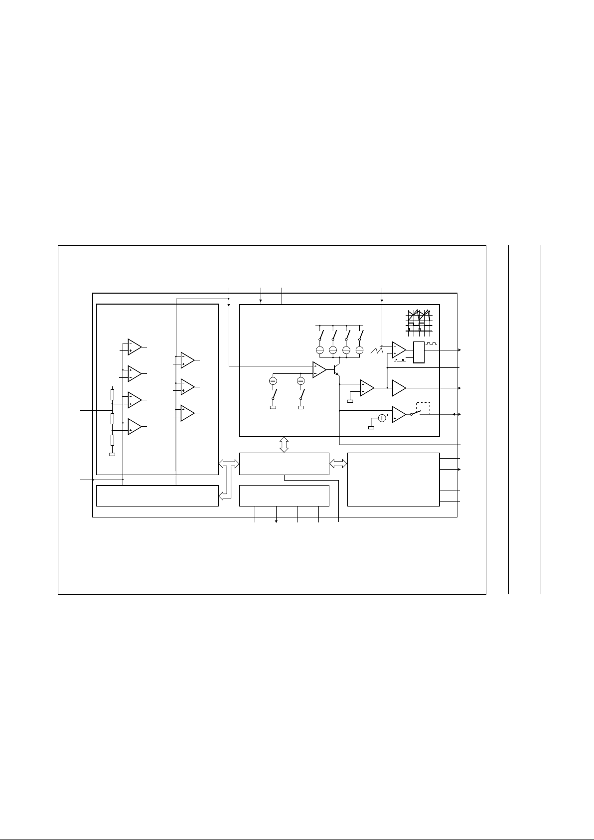
BLOCK DIAGRAM
handbook, full pagewidth
PROTECTION
NTC
present
T
cut-off
battery
low
end
refresh
nobattery
T
min
T
max
0.3 V
1 V
1.9 V
3.3 V
2.8 V
1 V
0.75 V
4.25 V
156
kΩ
36
kΩ
12
kΩ
DA/AD
CONVERTER
1.325 V/V
stb
NiCd
NIMH
1.9 V
nobattery
V
bat
V
reg
CHARGE CONTROL
AND
OUTPUT DRIVERS
fast
charge
1.25/R
ref
top
off
3 µA
standby
current
10 µA
load
current
40 µA
4.25 V
RSQ
LS
OSC
PWM
SET
A1
A4
100 mV
refresh
CONTROL LOGIC
SUPPLY
BLOCK
TIMER
AND
CHARGE
STATUS
INDICATION
V
bat
MTV
NTC
9
8
V
bat
V
stbRref
OSC
19 1 20 14
15
17
18
10
2
4
5
6
7
PWM
LS
AO
RFSH
IB
PSD
LED
POD
PTD
12 13 16 113
VPVslVSGND FCT
TEA1103
A2
A3
4×
MBH547
Fig.1 Block diagram.
1999 Jan 27 5
Philips Semiconductors Preliminary specification
Fast charge ICs for NiCd and NiMH
batteries
TEA1103; TEA1103T;
TEA1103TS
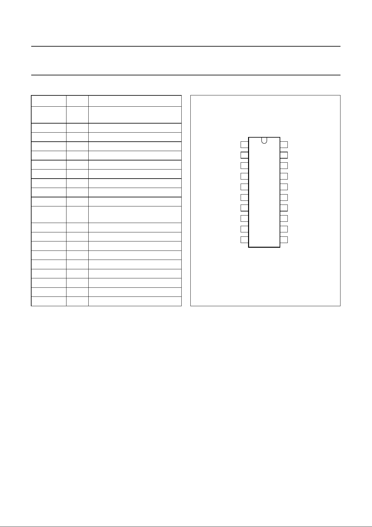
PINNING
SYMBOL PIN DESCRIPTION
V
stb
1 standby regulation voltage input
(NiCd and NiMH)
IB 2 charge current setting
GND 3 ground
PSD 4 program pin sample divider
LED 5 LED output
POD 6 program pin oscillator divider
PTD 7 program pin time-out divider
NTC 8 temperature sensing input
MTV 9 maximum temperature voltage
RFSH 10 refresh input/output
FCT 11 fast charge termination and
battery chemistry identification
V
P
12 positive supply voltage
V
sl
13 switched reference voltage output
OSC 14 oscillator input
PWM 15 pulse width modulator output
V
S
16 stabilized reference voltage
LS 17 loop stability pin
AO 18 analog output
V
bat
19 single-cell battery voltage input
R
ref
20 reference resistor pin
Fig.2 Pin configuration.
handbook, halfpage
TEA1103
MBH539
1
2
3
4
5
6
7
8
9
10
20
19
18
17
16
15
14
13
12
11
V
stb
R
ref
V
bat
V
sl
V
P
V
S
AO
LS
PWM
OSC
FCT
IB
GND
PSD
LED
POD
PTD
NTC
MTV
RFSH

1999 Jan 27 6
Philips Semiconductors Preliminary specification
Fast charge ICs for NiCd and NiMH
batteries
TEA1103; TEA1103T;
TEA1103TS
INTRODUCTION
All battery types are initially fast charged with an
adjustable high current. Fast charge termination depends
upon the battery type. With NiCd and NiMH batteries the
main fast charge termination will be the∆T/∆t (temperature
detection) and/or peak voltage detection.
The fast charge period is followed by a top-off period for
NiCd and NiMH batteries. During the top-off period the
NiCd and NiMH batteries are charged to maximum
capacity by reduced adjustable charge current.
The top-off period ends after time-out or one hour
respectively.
After the top-off period, the TEA1103x switches over to the
standby mode. For NiCd and NiMH batteries either the
voltage regulation or trickle charge mode can be selected.
The voltage regulation mode is selected when the battery
includes a fixed load. Trickle charge prevents a discharge
of the battery over a long period of time.
Charging principles
C
HARGING NiCd/NiMH BATTERIES
Fast charging of the battery begins when the power supply
voltage is applied and at battery insertion.
During fast charge of NiCd and NiMH batteries, the battery
temperature and voltage are monitored. Outside the
initialized temperature and voltage window, the system
switches over to the top-off charge current.
The TEA1103x supports detection of fully charged NiCd
and NiMH batteries by either of the following criteria:
•∆T/∆t
• Voltage peak detection.
If the system is programmed with ∆T/∆t and V
peak
or,∆T/∆t
or V
peak
as the main fast charge termination, it
automatically switches to voltage peak detection if the
battery pack is not provided with a temperature sensing
input (NTC). In this way both packages, with and without
temperature sensor, can be used randomly independent of
the applied full detection method. Besides ∆T/∆t and/or
voltage peak detection, fast charging is also protected by
temperature cut-off and time-out.
To avoid false fast charge termination by peak voltage
detection or ∆T/∆t, full detection is disabled during a short
hold-off period at the start of a fast charge session.
After fast charge termination, the battery is extra charged
by a top-off period. During this period of approximately one
hour, the charge current is lowered thus allowing the
battery to be charged to nearly 100% before the system
switches over to standby.
After the battery has been charged to nearly 100% by the
top-off period, discharge of the battery (caused by a load
or by the self-discharge) can be avoided by voltage
regulation or by trickle charge.
If batteries are charged in combination with a load, the
TEA1103x can be programmed to apply voltage regulation
during the standby mode. In this way, discharge of the
battery caused by self-discharge or by an eventual load is
avoided. The regulating voltage is adjustable to the
voltage characteristic of the battery. For battery safety the
charge current is limited and the temperature is monitored
during voltage regulation. If a trickle charge is applied, the
self-discharge of the battery will be compensated by a
pulsating charge current.
To avoid the so called ‘memory effect’ in NiCd batteries, a
refresh can be manually activated. The discharge current
is regulated by the IC in combination with an external
power transistor. After discharging the battery to 1 V per
cell, the system automatically switches over to fast charge.
FUNCTIONAL DESCRIPTION
Control logic
The main function of the control logic is to support the
communication between several blocks. It also controls
the charge method, initialization and battery full detection.
The block diagram of the TEA1103x is illustrated in Fig.1.
Conditioning charge method and initializations
At system switch-on, or at battery insertion, the control
logic sets the initialization mode in the timer block.
After the initialization time the timer program pins can be
used to indicate the charging state using several LEDs.
The charge method is defined at the same time by the
following methods:
• If the FCT pin is floating, the system will charge the
battery according to the charge characteristic of NiCd
and NiMH batteries.
• The standby charge method (NiCd and NiMH), trickle
charge or voltage regulation, is defined by the input pin
V
stb
. By biasing this voltage with a set voltage, the output
voltage will be regulated to the V
stb
set voltage. If this pin
is connected to VS, or no NTC is connected the system
applies trickle charge.

1999 Jan 27 7
Philips Semiconductors Preliminary specification
Fast charge ICs for NiCd and NiMH
batteries
TEA1103; TEA1103T;
TEA1103TS
If pin RFSH is connected to ground by depressing the
switch, the TEA1103x discharges the battery via an
external transistor connected to pin RFSH. The discharge
current is regulated with respect to the external (charge)
sense resistor (R
sense
). End-of-discharge is reached when
the battery is discharged to 1 V per cell. Refreshing the
battery can only be activated during charging of NiCd and
NiMH batteries.
The inhibit mode has the main priority. This mode is
activated when the V
stb
input pin is connected to ground.
Inhibit can be activated at any charge/discharge state,
whereby the output control signals will be zero, all LEDs
will be disabled and the charger timings will be set on hold.
Table 1 gives an operational summary.
Table 1 Functionality of program pins
Notes
1. Where X = don’t care.
2. Not low means floating or high.
3. The NTC voltage has been to be less than 3.3 V, which indicates the presence of an NTC.
4. The NTC voltage is outside the window for NTC detection.
5. V
stb
has to be floating or set to a battery regulating voltage in accordance with the specification.
FUNCTION FCT NTC RFSH V
stb
Inhibit X
(1)
X
(1)
X
(1)
low
Refresh not low
(2)
X
(1)
low not low
∆T/∆t detection floating note 3 not low not low
∆T/∆t and voltage peak detection high note 3 not low not low
Voltage peak detection not low note 4 not low not low
Trickle charge at standby not low X
(1)
not low high
not low note 4 not low not low
Voltage regulation at standby not low note 3 not low floating
(5)
Supply block
The supply block delivers the following outputs:
• A power-on reset pulse to reset all digital circuitry at
battery insertion or supply switch-on. After a general
reset the system will start fast charging the battery.
• A 4.25 V stabilized voltage source (VS) is externally
available. This source can be used to set the thermistor
biasing, to initialize the programs, to supply the external
circuitry for battery voltage based charge indication and
to supply other external circuitry.
• A 4.25 V bias voltage (V
sl
) is available for use for more
indication LEDs. This output pin will be zero during the
initialization period at start-up, thus avoiding any
interference of the extra LEDs when initializing.
Charge control
The charge current is sensed via a low-ohmic resistor
(R
sense
), see Fig.4. A positive voltage is created across
resistor Rb by means of a current source I
ref
which is set by
R
ref
in the event of fast charge and by an internal bias
current source in the event of top-off and trickle charge
(IIB), see Fig.1. The positive node of Rb will be regulated to
zero via error amplifier A1, which means that the voltage
across Rb and R
sense
will be the same. The fast charge
current is defined by the following equation:
(1)
The output of amplifier A1 is available at the loop stability
pin LS, consequently the time constant of the current loop
can be set. When V
peak
(NiCd and NiMH) is applied, the
current sensing for the battery voltage will be reduced,
implying that the charge current will be regulated to zero
during:
(2)
Actually battery voltage sensing takes place in the last
oscillator cycle of this period.
I
fastRsense
× RbI
ref
×=
t
sense
210POD× t
osc
×=

1999 Jan 27 8
Philips Semiconductors Preliminary specification
Fast charge ICs for NiCd and NiMH
batteries
TEA1103; TEA1103T;
TEA1103TS
To avoid modulation on the output voltage, the top-off
charge current is DC regulated, defined by the following
equation:
(3)
where:
(4)
The top-off charge current will be approximately 0.15CA,
which maximizes the charge in the battery under safe and
slow charging conditions. The top-off charge period will be
approximately one hour, so the battery will be extra
charged with approximately 0.15 Q. In this way the battery
is fully charged before the system switches over to
standby.
When pin 1 (V
stb
) is connected to VS, or no NTC is
connected the system compensates the (self) discharge of
the battery by trickle charge. The trickle charge current will
be pulsating, defined by the following equation:
(5)
During the non current periods at trickle charge the charge
current is regulated to zero, so that the current for a load
connected in series across the battery with the sense
resistor will be supplied by the power supply and not by the
battery.
If at pin 1 (V
stb
) a reference voltage is set in accordance
with the specification, and no NTC is connected the charge
mode will switch over from current to voltage regulation
after top-off. The reference regulating voltage can be
adjusted to the battery characteristic by external resistors
connected to pin V
stb
.
This reference voltage has to be selected in such a way
that it equals the rest voltage of the battery. By using
voltage regulation, the battery will not be discharged at a
load occurrence. If the V
stb
input pin is floating, the
TEA1103x will apply voltage regulation at 1.325 V during
the standby mode (NiCd and NiMH). The current during
voltage regulation is limited to 0.5CA. If the battery charge
current is maximized to 0.5CA for more than 2 hours
charging will be stopped. Moreover, if the temperature
exceeds T
max
, charging will be stopped completely.
As voltage regulation is referred to one cell, the voltage on
the V
bat
pin must be the battery voltage divided by the
number of cells (NiCd and NiMH).
When charging, the standby mode can only be entered
after a certain period of time depending on time-out.
To support full test of the TEA1103x at application, the
standby mode is also entered when V
bat<Vbat(l)
at top-off.
I
top off–
R
sense
× Rb310
6–
××=
t
top off–
227TOD× t
osc
×=
I
trickleRsense
× R
b
15
16
------
× 10
6–
×=
Timer
The timing of the circuit is controlled by the oscillator
frequency.
The timer block defines the maximum charging time by
‘time-out’. At a fixed oscillator frequency, the time-out time
can be adapted by the Programmable Time-out Divider
(PTD) using the following equation.
(6)
The time-out timer is put on hold by low voltage,
temperature protection and during the inhibit mode.
The Programmable Oscillator Divider (POD) enables the
oscillator frequency to be increased without affecting
the sampling time and time-out. Raising the oscillator
frequency will reduce the size of the inductive components
that are used.
At fast charging, after battery insertion, after refresh or
supply interruption, the full detector will be disabled for a
period of time to allow a proper start with flat or inverse
polarized batteries. This hold-off period is disabled at fast
charging by raising pin V
stb
to above ±5 V (once).
So for test options it is possible to slip the hold-off period.
The hold-off time is defined by the following equation:
(7)
Table 2 gives an overview of the settings of timing and
discharge/charge currents.
t
time out–
226POD× PTD× t
osc
×=
t
hold off–
25–t
time out–
×=

1999 Jan 27 9
Philips Semiconductors Preliminary specification
Fast charge ICs for NiCd and NiMH
batteries
TEA1103; TEA1103T;
TEA1103TS
Table 2 Timing and current formulae
SYMBOL DESCRIPTION FORMULAE
t
osc
timing see Fig.3
T
sampling
(∆T/∆t) NTC voltage sampling frequency
2
17
× POD × PSD × t
osc
T
sampling
(V
peak
) battery voltage sampling frequency
2
16
× POD × t
osc
t
top-off 2
27
× POD × t
osc
t
time-out 2
26
× POD × PTD × t
osc
t
hold-off 2
−5
× t
time-out
t
LED
inhibit or protection
2
14
× POD × t
osc
t
sense 2
10
× POD × t
osc
t
switch 2
21
× POD × PTD × t
osc
I
fast
charge/discharge currents
I
top-off
I
trickle
I
load-max
I
RFSH
R
b
R
sense
-----------------
V
ref
R
ref
----------
×
R
b
R
sense
-----------------
3× 10
6–
×
R
b
R
sense
-----------------
15
16
------
× 10
6–
×
R
b
R
sense
-----------------
40× 10
6–
×
100 mV
R
sense
--------------------
 Loading...