

Philips TEA1064BT-C1, TEA1064B-C1 Datasheet
DATA SH EET
Product specification
File under Integrated Circuits, IC03A
March 1994
INTEGRATED CIRCUITS
TEA1064B
Low voltage versatile telephone
transmission circuit with dialler
interface and transmit level
dynamic limiting
March 1994 2
Philips Semiconductors Product specification
Low voltage versatile telephone transmission circuit
with dialler interface and transmit level dynamic limiting
TEA1064B
FEATURES
• Low DC line voltage; operates down to 1.8 V (excluding
polarity guard)
• Voltage regulator with low voltage drop and adjustable
static resistance
• DC line voltage adjustment facility
• Provides a supply for external circuits
• Dynamic limiting (speech-controlled) in transmit
direction prevents distortion of line signal and sidetone
• Symmetrical high-impedance inputs (64 kΩ) for
dynamic, magnetic or piezo-electric microphones
• Asymmetrical high-impedance input (32 kΩ) for electret
microphones
• DTMF signal input
• Confidence tone in the earpiece during DTMF dialling
• Mute input for disabling speech during pulse or DTMF
dialling
• Power-down input for improved performance during
pulse dial or register recall (flash)
• Receiving amplifier for dynamic, magnetic or
piezo-electric earpieces
• Large amplification setting ranges on microphone and
earpiece amplifiers
• Line loss compensation (line current dependent) for
microphone and earpiece amplifiers (not used for DTMF
amplifier)
• Gain control curve adaptable to exchange supply
• Automatic disabling of the DTMF amplifier in
extremely-low voltage conditions
• Microphone MUTE function available with switch
• MUTE, POWER-DOWN and DTMF input reference (pin
V
EE2
) can be connected either to V
EE1
or SLPE.
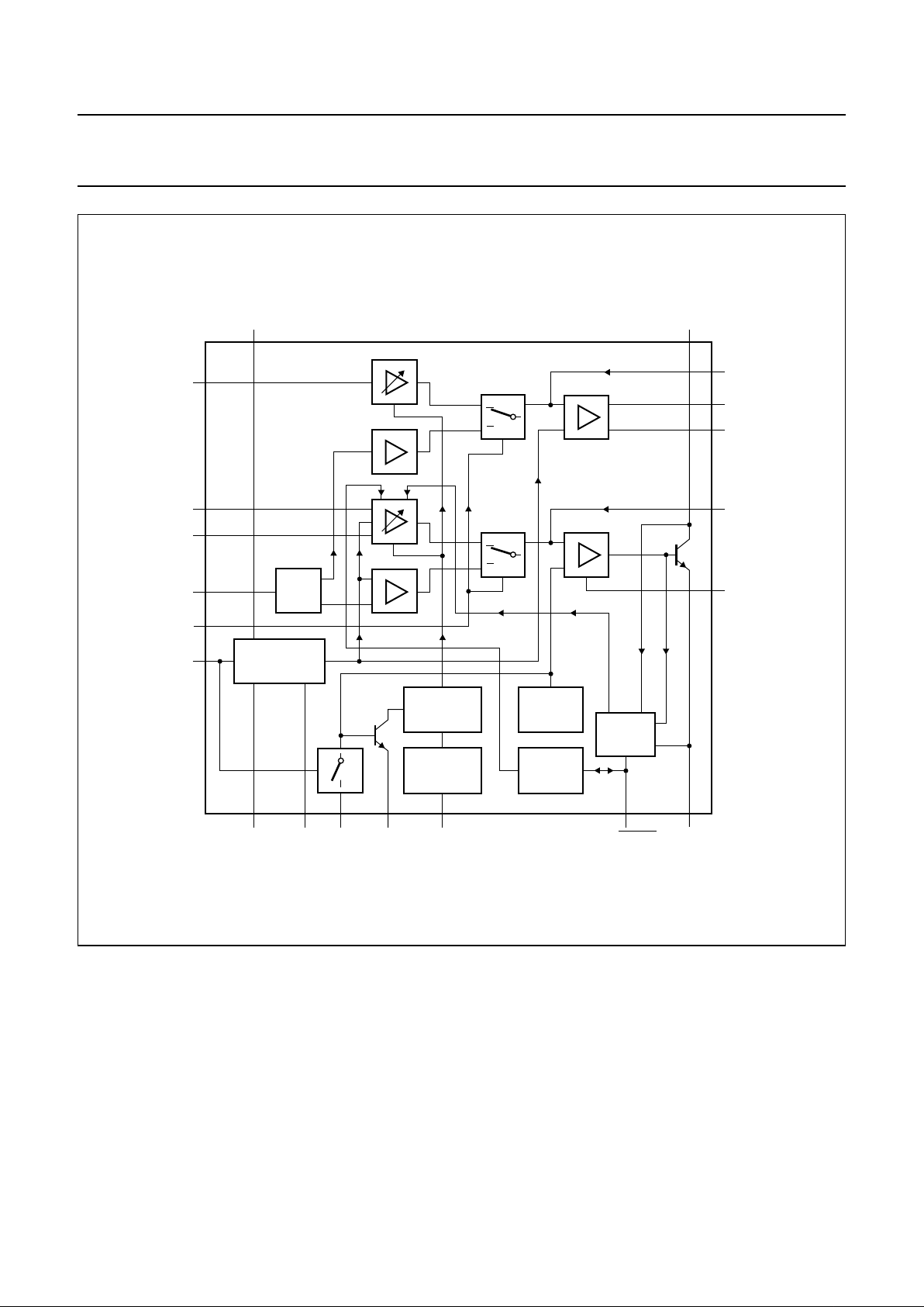
GENERAL DESCRIPTION
The TEA1064B is a bipolar integrated circuit that performs
all the speech and line interface functions required in fully
electronic telephone sets. It performs electronic switching
between dialling and speech. The IC operates at line
voltages down to 1.8 V DC (with reduced performance) to
facilitate the use of more telephone sets connected in
parallel. The transmit signal on the line is dynamically
limited (speech-controlled) to prevent distortion at high
transmit levels of both the sending signal and the sidetone.
ORDERING INFORMATION
Notes
1. SOT146-1; 1998 Jun 18.
2. SOT163-1; 1998 Jun 18.
EXTENDED TYPE
NUMBER
PACKAGE
PINS PIN POSITION MATERIAL CODE
TEA1064B 20 DIL plastic SOT146
(1)
TEA1064BT 20 mini-pack plastic SO20; SOT163A
(2)
March 1994 3
Philips Semiconductors Product specification
Low voltage versatile telephone transmission circuit
with dialler interface and transmit level dynamic limiting
TEA1064B
QUICK REFERENCE DATA
Note
1. For the TEA1064BT the maximum line current depends on the heat dissipating qualities of the mounted device.
SYMBOL PARAMETER CONDITIONS MIN. TYP. MAX. UNIT
I
line
line current operating range
normal operation note 1 11 − 140 mA
with reduced performance 2 − 11 mA
I
CC
internal supply current VCC = 2.8 V
power-down input LOW − 1.3 1.6 mA
power-down input HIGH − 60 82 µA
G
v
voltage gain range
microphone amplifier 44 − 52 dB
receiving amplifier 20 − 45 dB
line loss compensation ranges
G
v
gain control 5.7 6.1 6.5 dB
V
exch
exchange supply voltage 36 − 60 V
R
exch
exchange feeding bridge resistance 400 − 1000 Ω
V
LN(p-p)
maximum output voltage swing on LN
(peak-to-peak value)
R16 = 392 Ω;
I
line
= 15 mA
I
p
= 1.4 mA 3.55 3.80 4.05 V
I
p
= 2.7 mA 3.25 3.50 3.75 V
V
p
supply for peripherals I
line
= 15 mA
I
p
= 1.4 mA 2.5 2.7 − V
I
p
= 2.7 mA;
R
REG-SLPE
= 20 kΩ
2.9 3.1 − V
V
LN
DC line voltage I
line
= 15 mA
without R
REG-SLPE
3.25 3.5 3.75 V
R
REG-SLPE
= 20 kΩ 4.05 4.4 4.75 V
T
amb
operating ambient temperature range −25 −+75 °C
March 1994 4
Philips Semiconductors Product specification
Low voltage versatile telephone transmission circuit
with dialler interface and transmit level dynamic limiting
TEA1064B
Fig.1 Block diagram.
handbook, full pagewidth
+
MBA442
CURRENT
REFERENCE
START
CIRCUIT
DYNAMIC
LIMITER
LOW
VOLTAGE
CIRCUIT
AGC
CIRCUIT
SUPPLY AND
REFERENCE
171911
V
EE1VEE2
REG AGC STAB
DLS/MMUTE
SLPE
GAS2
GAS1
QR−
QR+
GAR
LN
V
CC
15
14
12
dB
8
9
+
−
+
−
18 10 7 20
13
IR
MIC+
MIC−
DTMF
MUTE
PD
+
−
+
−
−
116
TEA1064B
6
5
4
2
3
March 1994 5
Philips Semiconductors Product specification
Low voltage versatile telephone transmission circuit
with dialler interface and transmit level dynamic limiting
TEA1064B
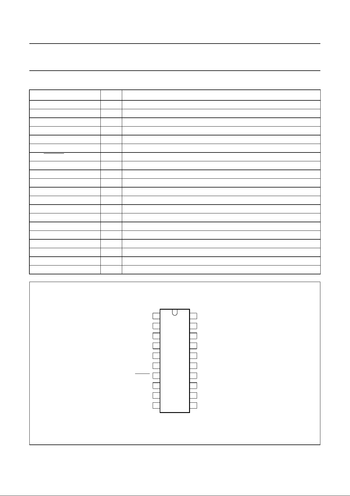
PINNING
SYMBOL PIN DESCRIPTION
LN 1 positive line terminal
GAS1 2 gain adjustment; transmitting amplifier
GAS2 3 gain adjustment; transmitting amplifier
QR− 4 inverting output; receiving amplifier
QR+ 5 non-inverting output; receiving amplifier
GAR 6 gain adjustment; receiving amplifier
DLS/
MMUTE 7 decoupling for transmit amplifier dynamic and microphone MUTE input
MIC− 8 inverting microphone input
MIC+ 9 non-inverting microphone input
STAB 10 current stabilizer
V
EE1
11 negative line terminal
DTMF 12 dual-tone multi-frequency input
IR 13 receiving amplifier input
MUTE 14 mute input
PD 15 power-down input
V
CC
16 internal supply decoupling
REG 17 voltage regulator decoupling
AGC 18 automatic gain control input
V
EE2
19 reference for POWER-DOWN (PD), MUTE and DTMF
SLPE 20 slope adjustment for DC curve/reference for peripheral circuits
Fig.2 Pin configuration.
handbook, halfpage
1
2
3
4
5
6
7
8
9
10
20
19
18
17
16
15
14
13
12
11
MBA433
TEA1064B
LN
GAS1
GAS2
QR−
QR+
GAR
DLS/MMUTE
MIC−
MIC+
STAB
SLPE
AGC
REG
PD
MUTE
IR
DTMF
V
EE1
V
EE2
V
CC
March 1994 6
Philips Semiconductors Product specification
Low voltage versatile telephone transmission circuit
with dialler interface and transmit level dynamic limiting
TEA1064B
FUNCTIONAL DESCRIPTION
Supplies V
CC
, V
EE2
, LN, SLPE, REG and STAB (Figs 3
and 5)
Power for the TEA1064B and its peripheral circuits is
usually obtained from the telephone line. The IC develops
its own supply voltage at V
CC
and regulates its voltage
drop. The internal supply requires a decoupling capacitor
between VCC and V
EE1
. The internal current stabilizer is
set by a 3.6 kΩ resistor between STAB and V
EE1
.
The DC current flowing into the set is determined by the
exchange supply voltage V
exch
, the feeding bridge
resistance R
exch
, the subscriber line DC resistance R
line
and the DC voltage (including polarity guard) on the
subscriber set (see Fig.3).
The internal voltage regulator generates a
temperature-compensated reference voltage that is
available between LN and SLPE (V
ref
= V
LN-SLPE
= 3.23 V
typ.). This internal voltage regulator requires decoupling
by a capacitor between REG and V
EE1
(C3).
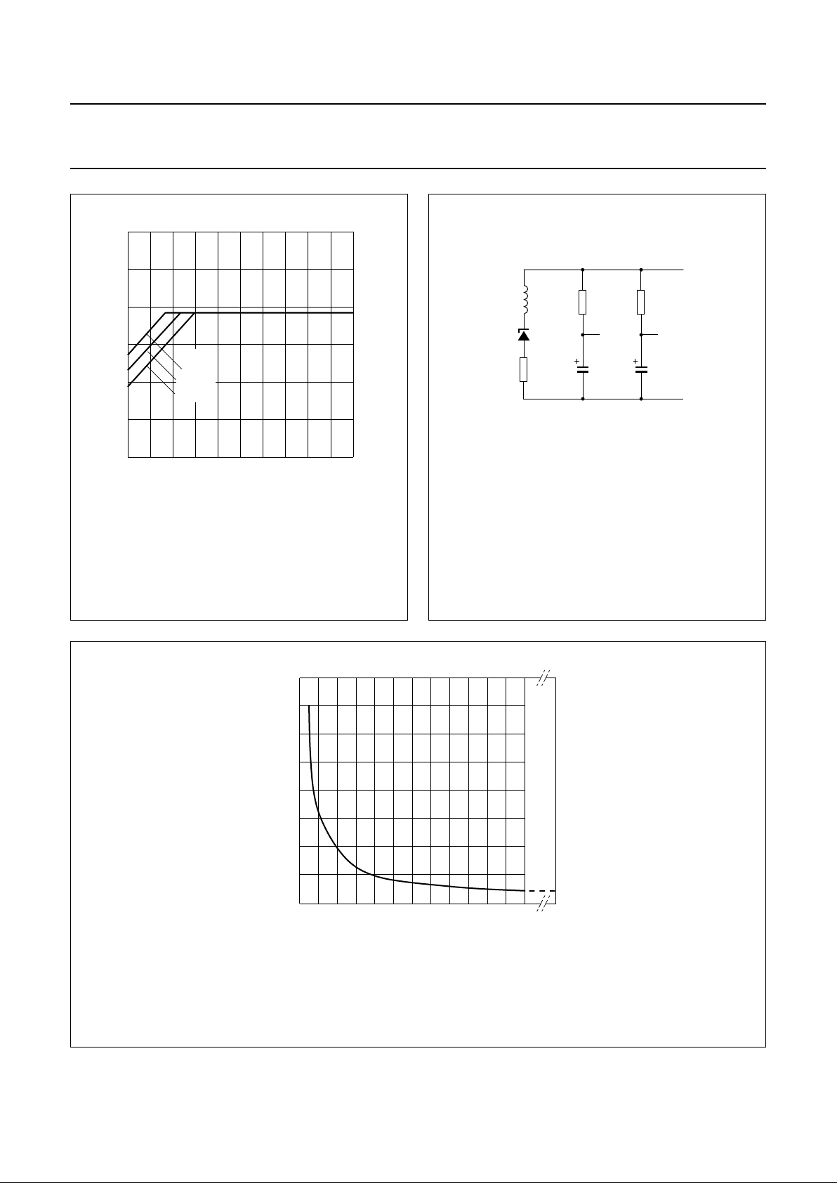
The configuration shown in Fig.3, gives a stabilized
voltage across pins LN and SLPE which, applied via the
low-pass filter R16, C15, provides a supply to the
peripherals that is independant of the line current and
depends only on the peripheral supply current.
The value of R16 and the level of the DC voltage V
LN-SLPE
determine the supply capabilities. In the basic application
R16 = 392 Ω and C15 = 220 µF. The worst-case
peripheral supply current as a function of supply voltage is
shown in Fig.4.
To increase the supply capabilities, the value of R16 can
be decreased or the DC voltage V
LN-SLPE
can be increased
by using R
VA(REG-SLPE)
.
Note
The TEA1064B application is the same as is used for
TEA1060/TEA1061, TEA1067 and TEA1068 integrated
circuits.
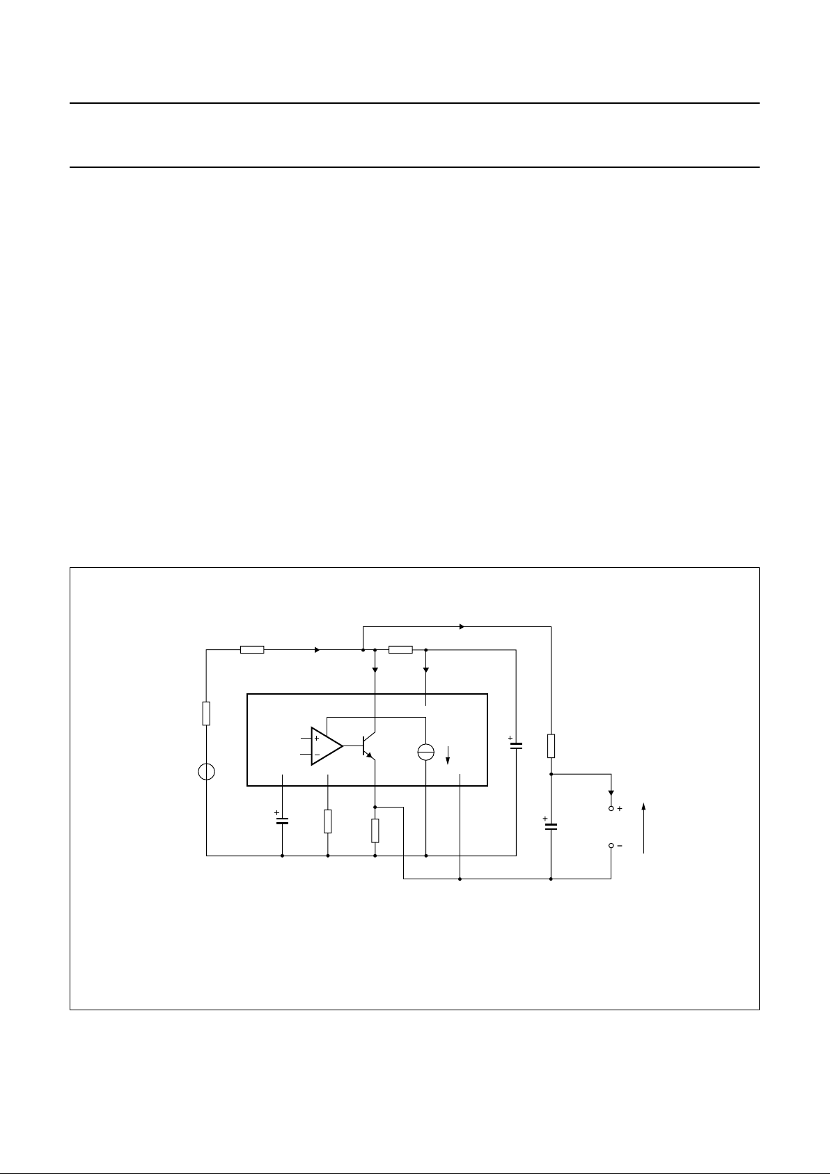
Fig.3 Supply arrangement with reference to SLPE.
The voltage V
LN-SLPE
is fixed to V
ref
= 3.323 ±0.25 V.
Resistor R16 together with the line current determine the supply capabilities and the maximum output swing on
the line (no loop damping is necessary).
The line voltage V
LN=Vref
+ ({I
line
− 1.55 mA}× R9).
handbook, full pagewidth
MBA435
R
exch
R
line
I
line
V
exch
DC
AC
17
REG
C3 R5
R9
10
STAB20SLPE
LN
1
V
CC
16
11
V
EE1
19
V
EE2
0.25 mA
R1
I
SLPE
+ 0.25 mA
I
CC
R16C1
C15
peripheral
circuits
V
p
I
p
TEA1064B
Ip + 0.25 mA
March 1994 7
Philips Semiconductors Product specification
Low voltage versatile telephone transmission circuit
with dialler interface and transmit level dynamic limiting
TEA1064B
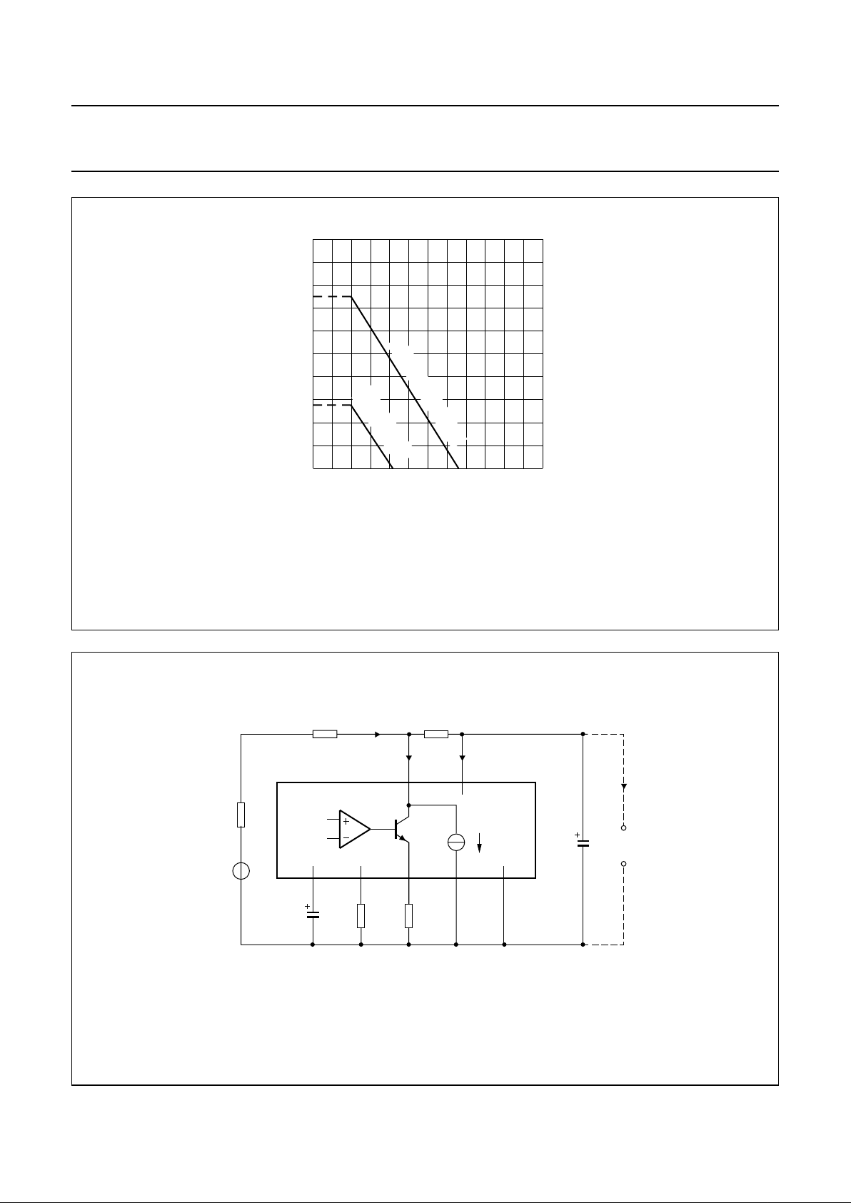
Fig.4 Maximum supply current with respect to Fig.3 for peripherals (Ip) as a function of the peripheral supply
voltage (Vp).
I
line
= 15 mA; R16 = 392 Ω; valid for MUTE = 0 and 1.
Line current has very little influence.
handbook, halfpage
2345
5
0
MBA436
4
3
2
1
Vp (V)
I
p
(mA)
R
VA(REG-SLPE)
= 20 kΩ
without
R
VA(REG-SLPE)
Fig.5 Supply arrangement with reference to V
EE1
.
handbook, full pagewidth
MBA432
SLPE
STAB
REG V
EE1
I
p
LN
116
20
11
V
EE2
17 10 19
TEA1064B
AC
DC
peripheral
circuits
C1
0.25 mA
I
SLPE
+ 0.25 mA
R
line
R
exch
V
exch
I
line
R1
V
CC
I
CC
C3 R5 R9
March 1994 8
Philips Semiconductors Product specification
Low voltage versatile telephone transmission circuit
with dialler interface and transmit level dynamic limiting
TEA1064B
The maximum AC output swing on the line at low currents
is influenced by R16 (limited by current) and the maximum
output swing on the line at high currents is influenced by
DC voltage V
LN-SLPE
(limited by voltage). In both these
situations, the internal dynamic limiter in the sending
channel prevents distortion when the microphone is
overdriven. The maximum AC output swing on LN is
shown in Fig.7; practical values for R16 are from 200 Ω to
600 Ω and this influences both maximum output swing at
low line currents and the supply capabilities.
When the SLPE pin is the reference for peripheral circuits,
inputs MUTE, PD and DTMF must be referenced to SLPE.
This is achieved by connecting pin V
EE2
to pin SLPE; V
EE2
being the reference of MUTE, PD and DTMF input stages.
Active microphones can be supplied between VCC and
V
EE1
as shown in Fig.5. Low power circuits that provide
MUTE, PD and DTMF inputs to the TEA1064B can also be
powered from VCC (see Fig.6 for the supply capability of
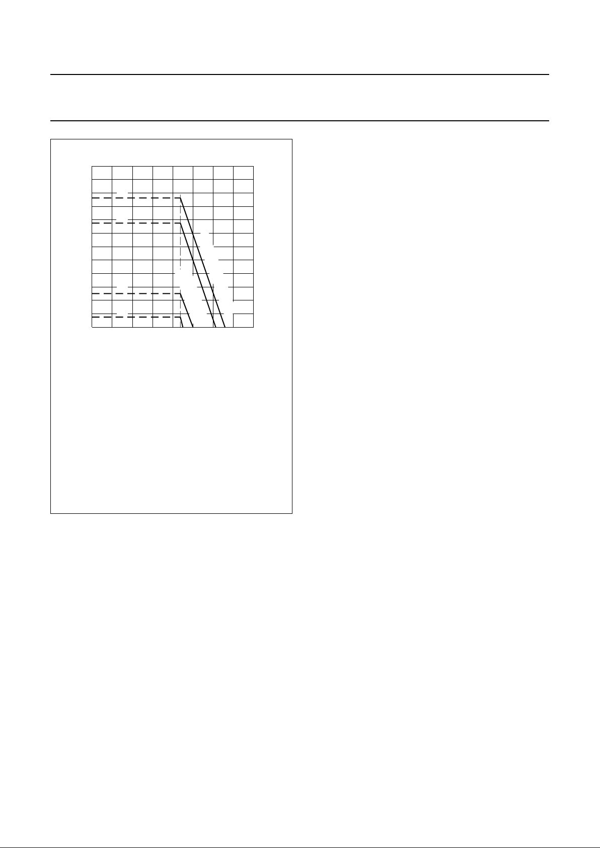
Fig.6 Maximum current Ipwith respect to Fig.5
available from Vccfor peripheral circuitry
with VCC> 2.2 V.
(a) Ip= 1.94 mA
(b) I
p
= 1.54 mA
(a′) I
p
= 0.54 mA
(b′)I
p
= 0.16 mA
I
line
=15mA
R1 = 620 Ω and R9 = 20 Ω
Curve (a) and (a′) are valid when the receiving
amplifier is not driven or when MUTE = HIGH.
Curve (b) and (b′) are valid when the receiving
amplifier is driven and when MUTE = LOW.
V
o(RMS)
= 150 mV, RT= 150 Ω.
handbook, halfpage
012 4
2.4
0
0.8
1.6
MBA434
3
VCC (V)
I
p
(mA)
(a)
(b)
(a')
(b')
R
VA(REG-SLPE)
= 20 kΩ
without
R
VA(REG-SLPE)
VCC). MUTE, PD and DTMF are then referenced to V
EE1
and the pin V
EE2
must therefore be connected to V
EE1
.
If the line current I
line
exceeds ICC+ 0.25 mA, the voltage
converter shunts the excess current to SLPE via LN;
where ICC≈ 1.3 mA, the value required by the IC for
normal operation.
The DC line voltage on LN is:
• VLN = V
LN-SLPE
+ (I
SLPE
x R9)
• VLN = V
ref
+ ({I
line
− ICC− 0.25 x 10⁻³ A} x R9)
in which:
• V
ref
= 3.23 V ± 0.25 V is the internal reference voltage
between LN and SLPE; its value can be adjusted by
external resistor RVA.
• R9 = external resistor between SLPE and V
EE1
(20 Ω in
basic operation).
With R9 = 20 Ω, this results in:
• VLN = 3.3 ± 0.25 V at I
line
= 15 mA
• VLN = 4.1 ± 0.3 V at I
line
= 15 mA, R
VA(REG-SLPE)
= 33 kΩ
• VLN = 4.4 ± 0.35 V at I
line
= 15mA,
R
VA(REG- SLPE)
= 20 kΩ
The preferred value for R9 is 20 Ω. Changing R9
influences microphone gain, DTMF gain, the gain control
characteristics, sidetone and the DC characteristics
(especially the low voltage characteristics).
In normal conditions, I
SLPE
>> (ICC+ 0.25 mA) and the
static behaviour is equivalent to a voltage regulator diode
with an internal resistance of R9. In the audio frequency
range the dynamic impedance is determined mainly by R1.
The equivalent impedance of the circuit in audio frequency
range is shown in Fig.8.
The internal reference voltage V
LN-SLPE
can be increased
by external resistor R
VA(REG-SLPE)
connected between
REG and SLPE. The voltage V
LN-SLPE
is shown as a
function of R
VA(REG-SLPE)
in Fig.9. Changing the reference
voltage influences the output swing of both sending and
receiving amplifiers.
At line currents below 8 mA (typ.), the DC voltage dropped
across the circuit is adjusted to a lower level automatically
(approximately 1.8 V at 2 mA). This gives the possibility of
operating more telephone sets in parallel with DC line
voltages (excluding polarity guard) down to an absolute
minimum of 1.8 V. At line currents below 8 mA (typ.), the
circuit has limited sending and receiving levels.
March 1994 9
Philips Semiconductors Product specification
Low voltage versatile telephone transmission circuit
with dialler interface and transmit level dynamic limiting
TEA1064B
Fig.7 Typical AC output swing at total harmonic
distortion (THD) = 2% on the line as a
function of line current with peripheral
supply current as a parameter.
R16 = 392 Ω; Ipwith respect to Fig.3.
handbook, halfpage
10
6
4
2
0
20 30
MBA437
V
LN(p-p)
(V)
I
line
(mA)
Ip =
0 mA
1.4 mA
2.7 mA
Fig.8 Equivalent impedance between LN and
VEE.
Leq=C3×R9 × R
p
Rp=15kΩ
handbook, halfpage
MBA438
R9
20 Ω
REG
LN
C3
4.7 µF
R
p
V
ref
L
eq
V
CC
V
EE1
C1
R1
Fig.9 Internal reference voltage V
LN-SLPE
as a function of resistor R
VA(REG-SLPE)
for line currents between 11 mA
and 140 mA.
VLN=V
LN-SLPE
+ ({I
line
− 1.55 × 10⁻³A} × R9).
handbook, full pagewidth
7.8
3.0
08040 120
MBA467
4.2
5.4
6.6
RVVA (REG-SLPE) (kΩ)
V
ref
(V)
with R
VA
infinite
March 1994 10
Philips Semiconductors Product specification
Low voltage versatile telephone transmission circuit
with dialler interface and transmit level dynamic limiting
TEA1064B
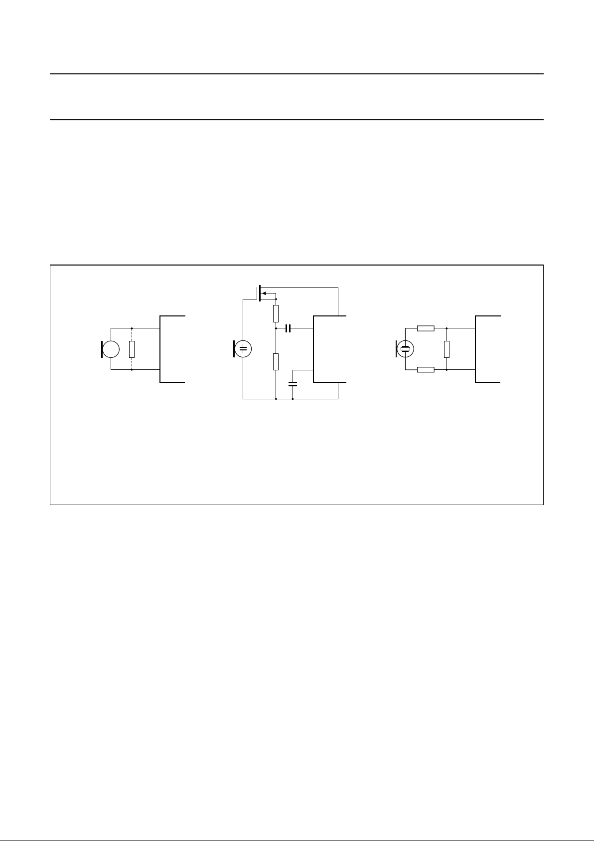
Microphone inputs MIC+ and MIC− and gain pins
GAS1 and GAS2
The TEA1064B has symmetrical microphone inputs, its
input impedance is 64 kΩ (2 x 32 kΩ) and its voltage
amplification is typically 52 dB with R7 = 68 kΩ. Either
dynamic, magnetic or piezo-electric microphones can be
used, or an electret microphone with a built-in FET buffer.
Arrangements for the microphone types are shown in
Fig.10.
The gain of the microphone amplifier is proportional to
external resistor R7 connected between GAS1 and GAS2
and with this it can be adjusted between 44 dB and
52 dB to suit the sensitivity of the transducer.
An external 100 pF capacitor (C6) is required between
GAS1 and SLPE to ensure stability. A larger value of C6
may be chosen to obtain a first-order low-pass filter with a
cut-off frequency corresponding to the time constant
R7 x C6.
Fig.10 Microphone arrangements (a) magnetic or dynamic microphone (b) electret microphone (c) piezo-electric
microphone currents.
Resistor (1) may be connected to reduce the terminating impedance, or for sensitive types a resistive attenuator
can be used to prevent overloading the microphone inputs.
handbook, full pagewidth
MBA439
V
EE1
V
CC
16
8
9
11
9
8
(1)
(a) (b)
(c)
MIC+
MIC−
MIC−
MIC+
9
8
MIC−
MIC+
 Loading...