

Philips TDA8440-C3 Datasheet

DATA SH EET
Product specification
File under Integrated Circuits, IC02
November 1985
INTEGRATED CIRCUITS
TDA8440
Switch for CTV receivers

November 1985 2
Philips Semiconductors Product specification
Switch for CTV receivers TDA8440
GENERAL DESCRIPTION
The TDA8440 is a versatile video/audio switch, intended to
be used in CTV receivers equipped with an AUXILIARY
VIDEO/AUDIO plug.
It provides two 3-state switches for audio channels and
one 3-state switch for the video channel and a video
amplifier with selectable gain (times 1 or times 2).
The integrated circuit can be used in conjunction with a
microcontroller from the MAB8400 family, and is controlled
via a bidirectional I2C bus. Sufficient sub-addressing is
provided for the I2C bus mode. It can also be controlled
directly by d.c. switching signals.
Features
• Combined analogue and digital circuitry gives maximum
flexibility in channel switching
• 3-state switches for all channels
• Selectable gain for the video channels
• Sub-addressing facility
• I2C bus or non-I2C bus mode (controlled by d.c.
voltages)
• Slave receiver in the I2C bus mode
• External OFF command
• System expansion possible up to 7 devices (14 sources)
• Static short-circuit proof outputs
QUICK REFERENCE DATA
PACKAGE OUTLINE
18-lead DIL; plastic (SOT102); SOT102-1; 1996 November 19.
Supply voltage range V
15-4
10 to 13,2 V
Supply current (without load) I
15
typ. 33 mA
max. 50 mA
Storage temperature T
stg
max. + 125 °C
Operating ambient temperature range T
amb
0 to + 70 °C
November 1985 3
Philips Semiconductors Product specification
Switch for CTV receivers TDA8440
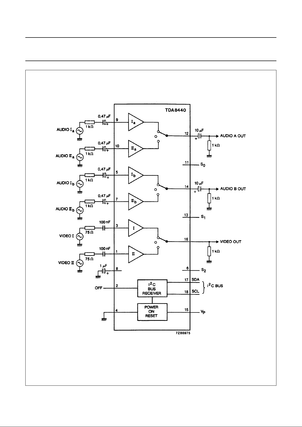
Fig.1 Block diagram and test circuit.
S0, S1, S2 and OFF (pins 11, 13, 6 and 2) connected to VP or GND.
If more than 1 device is used, then the outputs and the pins 8 (bias decoupling of the audio inputs) may be connected in parallel.

November 1985 4
Philips Semiconductors Product specification
Switch for CTV receivers TDA8440
FUNCTIONAL DESCRIPTION
The TDA8440 is a monolithic system of switches and can be used in CTV receivers equipped with an AUXILIARY
VIDEO/AUDIO plug.
The IC incorporates 3-state switches; they comprise:
a) An electronic video switch with selectable gain (times 1 or times 2) for switching between an internal video signal
(from the IF amplifier) and an AUXILIARY input signal.
b) Two electronic audio switches, for two sound channels (stereo or dual language), for switching between internal
audio sources and signals from the AUXILIARY VIDEO/AUDIO plug.
A selection can be made between two input signals and an OFF-state. The OFF-state is necessary if more than one
TDA8440 device is used.
The SDA and SCL pins can be connected to the I2C bus or to d.c. switching voltages. Inputs S0(pin 11), S1(pin 13), and
S2(pin 6) are used for selection of sub-addresses or switching to the non-I2C mode. Inputs S0, S1and S2can be
connected to the supply voltage (H) or to ground (L). In this way no peripheral components are required for selection.
Table 1 Sub-addressing
NON-I
2
C BUS CONTROL
If the TDA8440 switching device has to be operated via the AUXILIARY VIDEO/AUDIO plug, inputs S2, S1and S0must
be connected to the supply line (12 V).
The sources (internal and external) and the gain of the video amplifier can be selected via the SDA and SCL pins with
the switching voltage from the AUXILIARY VIDEO/AUDIO plug:
• Sources I are selected if SDA = 12 V (external source)
• Sources II are selected if SDA = 0 V (TV mode)
• Video amplifier gain is 2 × if SCL = 12 V (external source)
• Video amplifier gain is 1 × if SCL = 0 V (TV mode)
If more than one TDA8440 device is used in the non-I2C bus system, the OFF pin can be used to switch off the desired
devices. This can be done via the 12 V switching voltage on the AUXILIARY VIDEO/AUDIO plug.
• All switches are in the OFF position if OFF = H (12 V)
• All switches are in the selected position via SDA and SCL pins if OFF = L (0 V)
S
2
S
1
S
0
SUB-ADDRESS
A
2
A
1
A
0
LL L000
LL H001
LH L010
LH H011
HL L100
HL H101
HH L110
H H H non I
2
C addressable
 Loading...