

Philips TDA8424-V7 Datasheet
DATA SH EET
Product specification
File under Integrated Circuits, IC02
September 1992
INTEGRATED CIRCUITS
TDA8424
Hi-Fi stereo audio processor;
I
2
C-bus
September 1992 2
Philips Semiconductors Product specification
Hi-Fi stereo audio processor; I2C-bus
TDA8424
FEATURES
• Mode selector
• Spatial stereo, stereo and forced mono switch
• Volume and balance control
• Bass, treble and mute control
• Power supply with power-on reset
GENERAL DESCRIPTION
The TDA8424 is monolithic bipolar integrated stereo
sound circuit with a loudspeaker channel facility, digitally
controlled via the I
2
C-bus for application in hi-fi audio and
television sound.
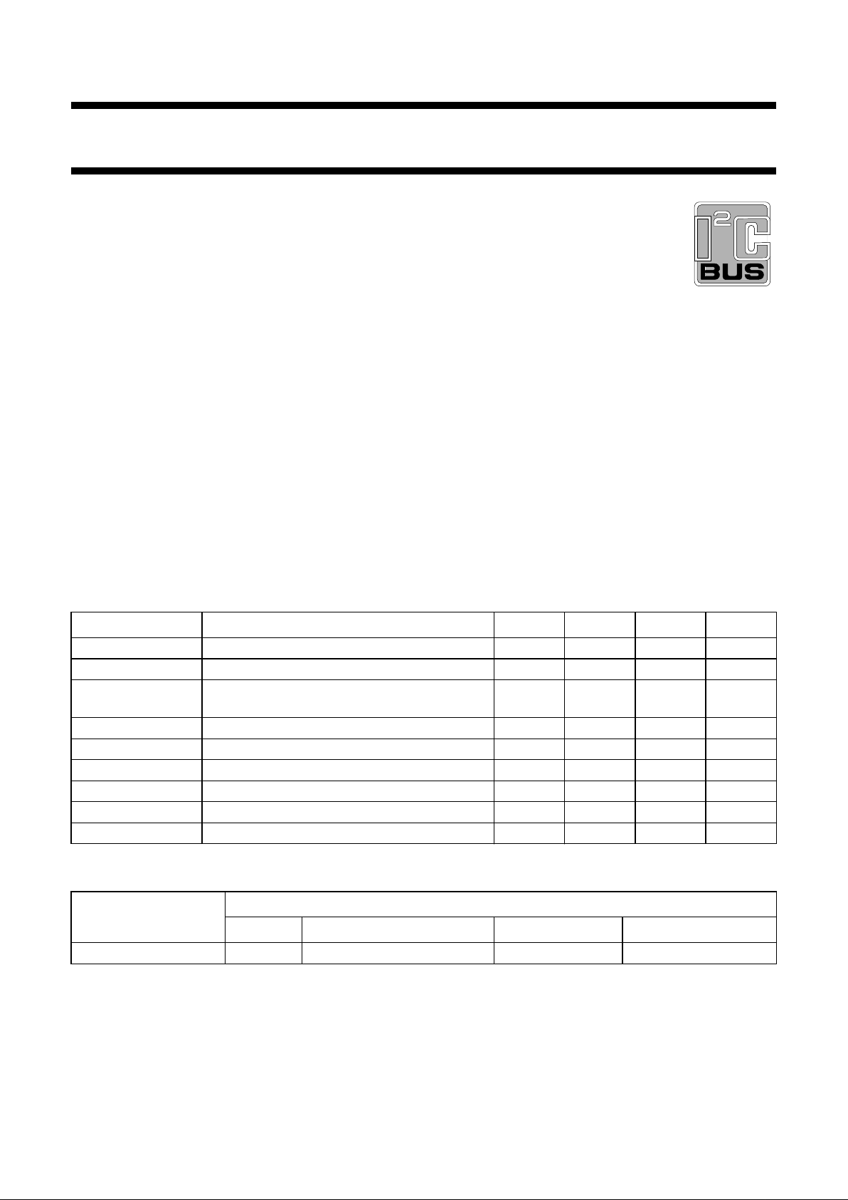
QUICK REFERENCE DATA
ORDERING INFORMATION
Note
1. SOT146-1; 1996 December 3.
SYMBOL PARAMETER MIN. TYP. MAX. UNIT
V
CC
positive supply voltage (pin 4) 10.8 12.0 13.2 V
V
I
input signal handling 2 −−V
V
i
input sensitivity with full power at the output
stage
− 300 − mV
(S+N)/N signal plus noise-to-noise ratio − 86 − dB
THD total harmonic distortion − 0.05 − %
α
cs
channel separation − 80 − dB
G
vol
volume control range −64 −+6dB
G
tre
treble control range −12 −+12 dB
G
bass
bass control range −12 −+15 dB
EXTENDED TYPE
NUMBER
PACKAGE
PINS PIN POSITION MATERIAL CODE
TDA8424 20 DIL plastic SOT146
(1)
September 1992 3
Philips Semiconductors Product specification
Hi-Fi stereo audio processor; I2C-bus
TDA8424
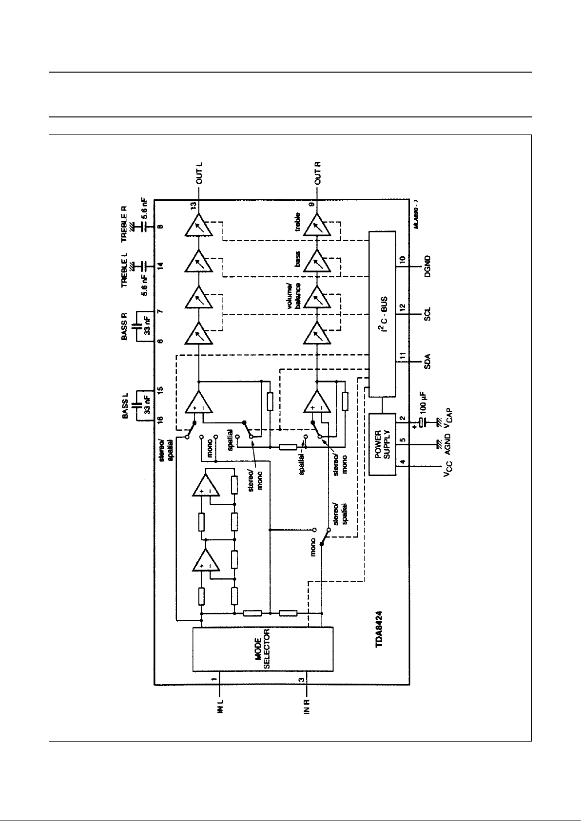
Fig.1 Block diagram.
September 1992 4
Philips Semiconductors Product specification
Hi-Fi stereo audio processor; I2C-bus
TDA8424
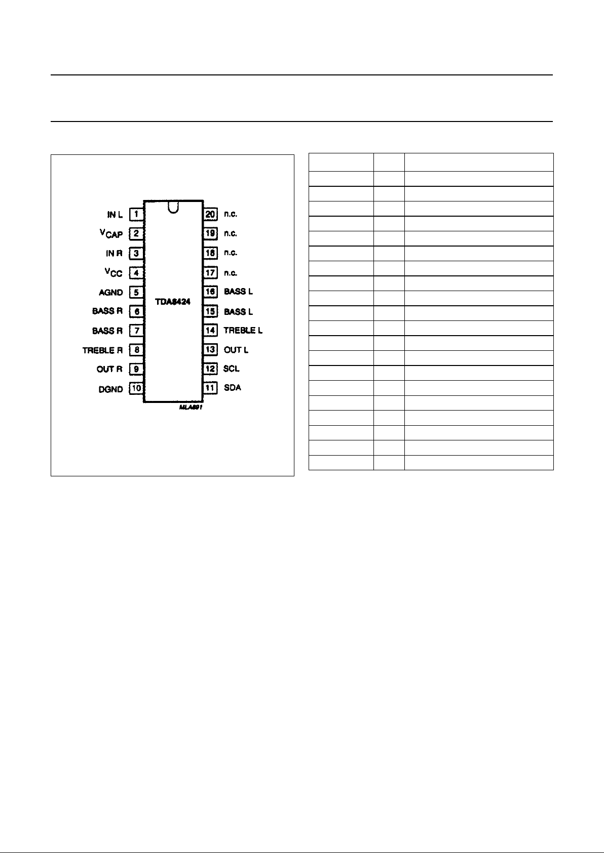
PINNING
Fig.2 Pin configuration.
SYMBOL PIN DESCRIPTION
IN L 1 left channel input
V
CAP
2 decoupling capacitor
IN R 3 right channel input
V
CC
4 positive supply voltage
AGND 5 analog ground
BASS R 6 right channel bass control
BASS R 7 right channel bass control
TREBLE R 8 right channel treble control
OUT R 9 right channel output
DGND 10 digital ground
SDA 11 serial data input/output
SCL 12 serial clock input
OUT L 13 left channel output
TREBLE L 14 left channel treble control
BASS L 15 left channel bass control
BASS L 16 left channel bass control
n.c. 17 not connected
n.c. 18 not connected
n.c. 19 not connected
n.c. 20 not connected
September 1992 5
Philips Semiconductors Product specification
Hi-Fi stereo audio processor; I2C-bus
TDA8424
FUNCTIONAL DESCRIPTION
Mode selector
The mode selector selects between stereo, sound A and
sound B (in the event of bi-lingual transmission) for OUT R
and OUT L.
Volume control and balance
The volume control consists of two stages (left and right).
In each part the gain can be adjusted between +6 dB and
−64 dB in steps of 2 dB. An additional step allows an
attenuation of ≥ 80 dB. Both parts can be controlled
independently over the whole range, which allows the
balance to be varied by controlling the volume of left and
right output channels.
Stereo, spatial stereo and forced mono mode
It is possible to select three modes: stereo, spatial stereo
or forced mono. The spatial stereo mode handles stereo
transmissions and the forced mono can be used in the
event of stereo signals.
Bass control
The bass control can be switched from an emphasis of
15 dB to an attenuation of 12 dB for low frequencies in
steps of 3 dB.
Treble control
The treble control stage can be switched
from +12 dB to −12 dB in steps of 3 dB.
Bias and power supply
The TDA8424 includes a bias and power supply stage,
which generates a voltage of 0.5 V
CC
with a low output
impedance and injector currents for the logic part.
Power-on reset
The on-chip power-on reset circuit sets the mute bit to
active, which mutes both parts of the treble amplifier. The
muting can be switched by transmission of the mute bit.
I
2
C-bus receiver and data handling
B
US SPECIFICATION
The TDA8424 is controlled via the 2-wire I2C-bus by a
microcontroller.
The two wires (SDA - serial data, SCL - serial clock) carry
information between the devices connected to the bus.
Both SDA and SCL are bi-directional lines, connected to a
positive supply voltage via a pull-up resistor.
When the bus is free both lines are HIGH.
The data on the SDA line must be stable during the HIGH
period of the clock. The HIGH or LOW state of the data line
can only change when the clock on the SCL line is LOW.
The set-up and hold times are specified in the AC
CHARACTERISTICS.
A HIGH-to-LOW transition of the SDA line while SCL is
HIGH is defined as a start condition.
A LOW-to-HIGH transition of the SDA line while SCL is
HIGH is defined as a stop condition.
The bus receiver will be reset by the reception of a start
condition. The bus is considered to be busy after the start
condition.
The bus is considered free again after a stop condition.
Module address
Data transmission to the TDA8424 starts with the module
address MAD.
Subaddress
After the module address byte a second byte is used to
select the following functions:
• Volume left, volume right, bass, treble and switch
functions
The subaddress SAD is stored within the TDA8424. Table
1 defines the coding of the second byte after the module
address MAD.
The automatic increment feature of the slave address
enables a quick slave receiver initialization, within one
transmission, by the I
2
C-bus controller (see Fig.5).
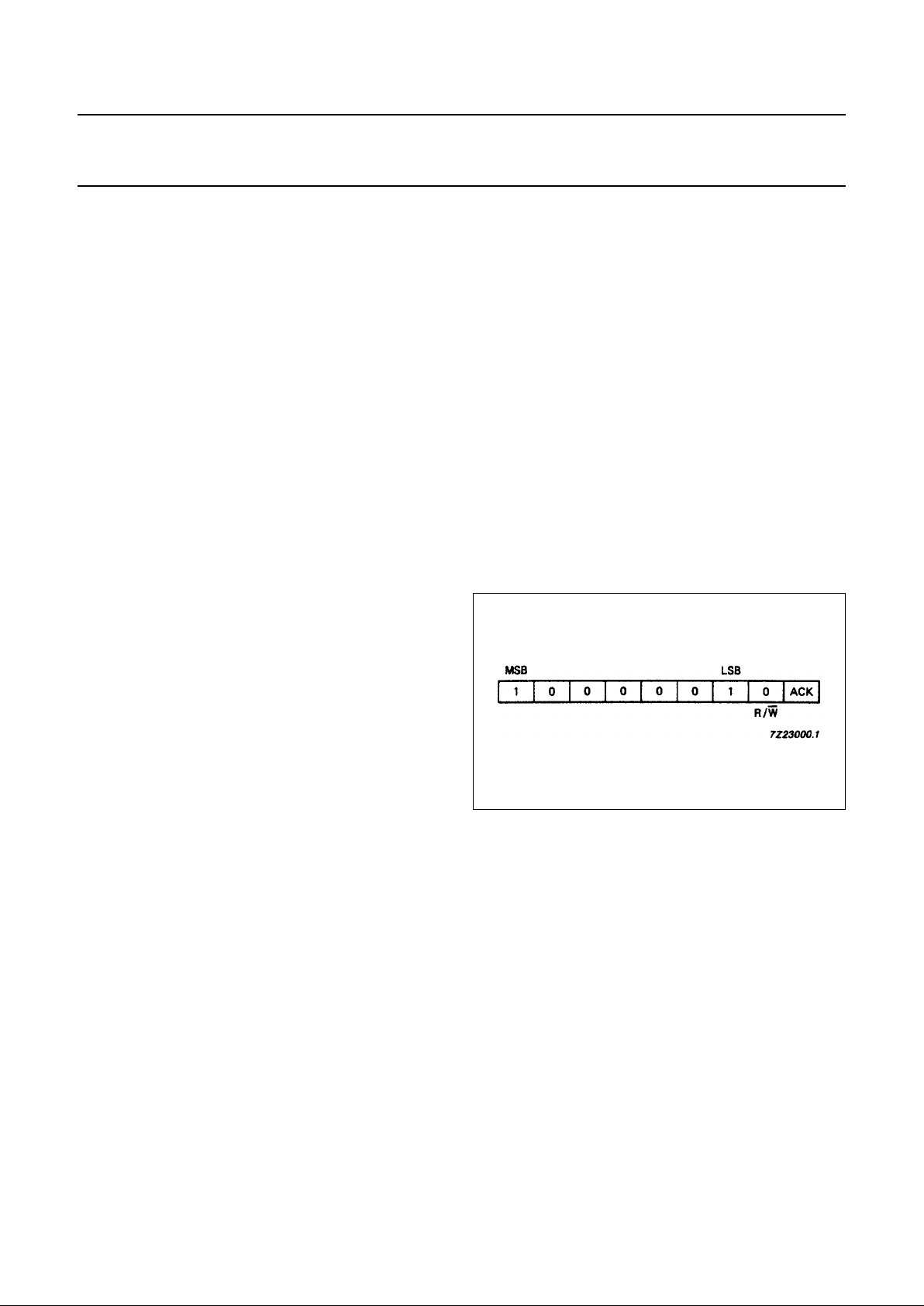
Fig.3 TDA8424 module address.
September 1992 6
Philips Semiconductors Product specification
Hi-Fi stereo audio processor; I2C-bus
TDA8424
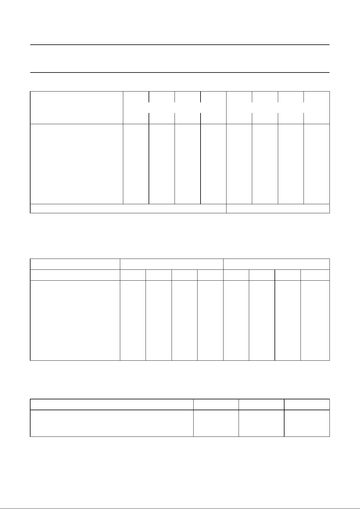
Table 1 Second byte after module address MAD
Definition of 3rd byte
A third byte is used to transmit data to the TDA8424. Table 2 defines the coding of the third byte after module address
MAD and subaddress SAD.
Table 2 Third byte after module address MAD and subaddress SAD
Truth tables
Tables 3, 4 and 5 are truth tables for the switch functions
Table 3 Mode selector
Note
1. Must be set to logic 1
FUNCTION
128 64 32 16 8 4 2 1
MSB LSB
76543210
Volume left 0 0 0 0 0 0 0 0
Volume right 0 0 0 0 0 0 0 1
Bass 0 0 0 0 0 0 1 0
Treble 0 0 0 0 0 0 1 1
00000000
00000000
00000000
00000000
Switch functions 0 0 0 0 1 0 0 0
subaddress SAD
MSB LSB
FUNCTION 7 6 5 4 3 2 1 0
Volume left VL 1 1 V05 V04 V03 V02 V01 V00
Volume right VR 1 1 V15 V14 V13 V12 V11 V10
Bass BA 1 1 1 1 BA3 BA2 BA1 BA0
Treble TR 1 1 1 1 TR3 TR2 TR1 TR0
1111111 1
1111111 1
1111111 1
1111111 1
Switch functions S1 1 1 MU EFL STL ML1 ML0 1
FUNCTION ML1 ML0 IS
Stereo 1 1 1
(1)
Sound A 0 1 1
(1)
Sound B 1 0 1
(1)
September 1992 7
Philips Semiconductors Product specification
Hi-Fi stereo audio processor; I2C-bus
TDA8424
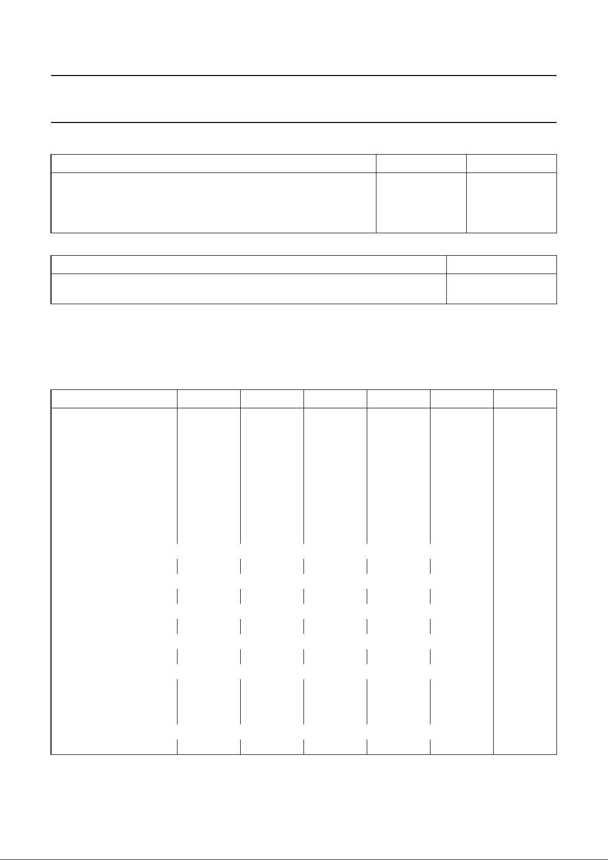
Table 4 Stereo/spatial stereo/forced mono
Table 5 Mute (see note 1)
Note
1. POR = Power-on reset.
Tables 6, 7 and 8 are truth tables for the volume, bass and treble controls
Table 6 Volume control
CHOICE STL EFL
Spatial stereo 1 1
Stereo 10
Forbidden status 0 1
Forced mono 0 0
MUTE MU
Active; automatic after POR 1
Not active 0
2 dB/STEP (dB) V × 5V×4V×3V×2V×1V×0
6 111111
4 111110
2 111101
0 111100
−2 111011
−4 111010
−6 111001
−8 111000
−10 110111
−20 110010
−30 101101
−40 101000
−50 100011
−60 011110
−62 011101
−64 011100
−80 011011
 Loading...