

Philips TDA8010M Service Manual

INTEGRATED CIRCUITS
DATA SH EET
TDA8010M; TDA8010AM
Low power mixers/oscillators
for satellite tuners
Objective specification
Supersedes data of 1996 Oct 08
File under Integrated Circuits, IC02
1996 Oct 24

Philips Semiconductors Objective specification
Low power mixers/oscillators
for satellite tuners
FEATURES
• Fully balanced mixer with common base input
• Wide input power and frequency range
• One-band 2 pin oscillator
• Local oscillator buffer and prescaler
• SAW filter IF preamplifier with gain control input and
switchable output
• Bandgap voltage stabilizer for oscillator stability
• External IF filter between the mixer output and the IF
amplifier input.
APPLICATIONS
• Down frequency conversion in DBS (Direct
Broadcasting Satellite) satellite receivers.
QUICK REFERENCE DATA
SYMBOL PARAMETER CONDITIONS MIN. TYP. MAX. UNIT
V
I
CC
f
RF
f
osc
NF
G
G
CC
M
max
min
supply voltage 4.5 5.0 5.5 V
supply current − 70 − mA
RF frequency range 700 − 2150 MHz
oscillator frequency 1380 − 2650 MHz
mixer noise figure corrected for image − 10 − dB
maximum total gain mixer plus IF − 40 − dB
minimum total gain mixer plus IF −−17 − dB
GENERAL DESCRIPTION
The TDA8010M; TDA8010AM are integrated circuits that
perform the mixer/oscillator function in satellite tuners.
The devices include a gain controlled IF amplifier that can
directly drive two single-ended SAW filters or a differential
SAW filter using a three function switchable output.
They contain an internal LO prescaler and buffer that is
compatible with the input of a terrestrial or satellite
frequency synthesizer. They are also suitable for digital TV
tuners. These devices are available in small outline
packages that give the designer the capability to design an
economical and physically small satellite tuner.
TDA8010M;
TDA8010AM
ORDERING INFORMATION
TYPE
NUMBER
TDA8010M
TDA8010AM
1996 Oct 24 2
NAME DESCRIPTION VERSION
SSOP20 plastic shrink small outline package; 20 leads; body width 4.4 mm SOT266-1
PACKAGE

Philips Semiconductors Objective specification
Low power mixers/oscillators
for satellite tuners
BLOCK DIAGRAM
handbook, full pagewidth
CC
20 (1)
19 (2)
18 (3)
17 (4)
16 (5)
15 (6)
14 (7)
13 (8)
12 (9)
11 (10)
OSCILLATOR
LOOUT2
LOOUT1
LOGND
OSC2
OSC1
OSCGND
IFOUT2
V
IFGND
IFOUT1
LO
BUFFER
OUTPUT
SWITCH
DIVIDE-BY-2
PRE-SCALER
SWITCH
CONTROL
TDA8010M
TDA8010AM
V
CC
TDA8010M; TDA8010AM
STABILIZER
RF INPUT
STAGE
IF AMP
R
AGC
(20) 1
(19) 2
(18) 3
(17) 4
(16) 5
(15) 6
(14) 7
(13) 8
(12) 9
(11) 10
SC
V
CCM
RFIN1
RFIN2
MGND
MOUT1
MOUT2
IFIN1
IFIN2
AGC
The pin numbers given in parenthesis refer to the TDA8010AM.
Fig.1 Block diagram.
MGE506
1996 Oct 24 3
Philips Semiconductors Objective specification
Low power mixers/oscillators
for satellite tuners
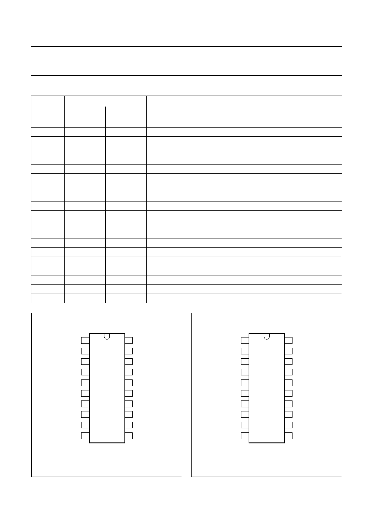
PINNING
SYMBOL
TDA8010M TDA8010AM
SC 1 20 IF output switch control
V
CCM
RFIN1 3 18 RF input 1
RFIN2 4 17 RF input 2
MGND 5 16 ground for mixer
MOUT1 6 15 mixer output 1
MOUT2 7 14 mixer output 2
IFIN1 8 13 IF amplifier input 1
IFIN2 9 12 IF amplifier input 2
AGC 10 11 IF amplifier gain control input
IFOUT1 11 10 IF amplifier output 1
IFGND 12 9 ground for IF amplifier
V
CC
IFOUT2 14 7 IF amplifier output 2
OSCGND 15 6 ground for oscillator
OSC1 16 5 oscillator tuning circuit input 1
OSC2 17 4 oscillator tuning circuit input 2
LOGND 18 3 ground for local oscillator buffer
LOOUT1 19 2 local oscillator output 1
LOOUT2 20 1 local oscillator output 2
PINS
2 19 supply voltage for mixer
13 8 supply voltage
TDA8010M; TDA8010AM
DESCRIPTION
handbook, halfpage
SC
V
CCM
RFIN1
RFIN2
MGND
MOUT1
MOUT2
IFIN1
IFIN2
AGC
1
2
3
4
5
6
7
8
9
10
TDA8010M
MGE504
20
19
18
17
16
15
14
13
12
11
LOOUT2
LOOUT1
LOGND
OSC2
OSC1
OSCGND
IFOUT2
V
CC
IFGND
IFOUT1
Fig.2 Pin configuration (TDA8010M).
1996 Oct 24 4
handbook, halfpage
LOOUT2
LOOUT1
OSCGND
Fig.3 Pin configuration (TDA8010AM).
LOGND
OSC2
OSC1
IFOUT2
V
CC
IFGND
IFOUT1
1
2
3
4
5
TDA8010AM
6
7
8
9
10
MGE505
20
19
18
17
16
15
14
13
12
11
SC
V
CCM
RFIN1
RFIN2
MGND
MOUT1
MOUT2
IFIN1
IFIN2
AGC
 Loading...