

Philips TDA7053-N1 Datasheet

DATA SH EET
Product specification
File under Integrated Circuits, IC01
February 1994
INTEGRATED CIRCUITS
TDA7053
2 x 1 W portable/mains-fed stereo
power amplifier

February 1994 2
Philips Semiconductors Product specification
2 x 1 W portable/mains-fed stereo
power amplifier
TDA7053
GENERAL DESCRIPTION
The TDA7053 is an integrated class-B stereo power amplifier in a 16-lead dual-in-line (DIL) plastic package. The device,
consisting of two BTL amplifiers, is primarily developed for portable audio applications but may also be used in mains-fed
applications.
Features
• No external components
• No switch-ON/OFF clicks
• Good overall stability
• Low power consumption
• Short-circuit-proof.
QUICK REFERENCE DATA
PACKAGE OUTLINE
16-lead DIL; plastic (SOT38); SOT38-1; 1996 July 24.
PARAMETER CONDITIONS SYMBOL MIN. TYP. MAX. UNIT
Supply voltage range V
P
3 6 18 V
Total quiescent current R
L
= ∞ I
tot
− 916mA
Output power R
L
= 8 Ω;
V
P
= 6 V P
O
− 1.2 − W
Internal voltage gain G
v
38 39 40 dB
Total harmonic distortion P
O
= 0.1 W THD − 0.2 1.0 %
February 1994 3
Philips Semiconductors Product specification
2 x 1 W portable/mains-fed stereo
power amplifier
TDA7053
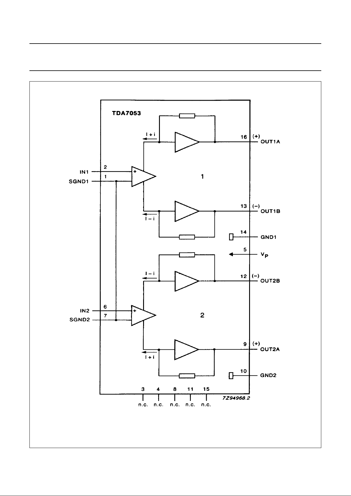
Fig.1 Block diagram.

February 1994 4
Philips Semiconductors Product specification
2 x 1 W portable/mains-fed stereo
power amplifier
TDA7053
PINNING
Note
The information contained within the parentheses refer to the polarity of the loudspeaker terminal to which the output
must be connected.
FUNCTIONAL DESCRIPTION
The TDA7053 is a stereo output amplifier, with an internal gain of 39 dB, which is primarily for use in portable audio
applications but may also be used in mains-fed applications. The current trends in portable audio application design is
to reduce the number of batteries which results in a reduction of output power when using conventional output stages.
The TDA7053 overcomes this problem by using the Bridge-Tied-Load (BTL) principle and is capable of delivering 1.2 W
into an 8 Ω load (V
P
= 6 V). The load can be short-circuited under all input conditions.
1. SGND1 signal ground 1 9. OUT2A output 2 (positive)
2. IN1 input 1 10. GND2 power ground 2
3. n.c. not connected 11. n.c. not connected
4. n.c. not connected 12. OUT2B output 2 (negative)
5. V
P
supply voltage 13. OUT1B output 1 (negative)
6. IN2 input 2 14. GND1 power ground 1
7. SGND2 signal ground 2 15. n.c. not connected
8. n.c. not connected 16. OUT1A output 1 (positive)
 Loading...