

Philips TDA7050T-N3-S6, TDA7050T-N3 Datasheet
DATA SH EET
Product specification
File under Integrated Circuits, IC01
July 1994
INTEGRATED CIRCUITS
TDA7050T
Low voltage mono/stereo power
amplifier

July 1994 2
Philips Semiconductors Product specification
Low voltage mono/stereo power amplifier TDA7050T
GENERAL DESCRIPTION
The TDA7050T is a low voltage audio amplifier for small radios with headphones (such as watch, pen and pocket radios)
in mono (bridge-tied load) or stereo applications.
Features
• Limited to battery supply application only (typ. 3 and 4 V)
• Operates with supply voltage down to 1,6 V
• No external components required
• Very low quiescent current
• Fixed integrated gain of 26 dB, floating differential input
• Flexibility in use − mono BTL as well as stereo
• Small dimension of encapsulation (see package design example).
QUICK REFERENCE DATA
PACKAGE OUTLINE
8-lead mini-pack; plastic (SO8; SOT96A); SOT96-1; 1996 July 24.
Supply voltage range V
P
1,6 to 6,0 V
Total quiescent current (at V
P
= 3 V) I
tot
typ. 3,2 mA
Bridge tied load application (BTL)
Output power at RL= 32 Ω
V
P
= 3 V; d
tot
= 10% P
o
typ. 140 mW
D.C. output offset voltage between the outputs |∆V| max. 70 mV
Noise output voltage (r.m.s. value)
at f = 1 kHz; R
S
= 5 kΩ V
no(rms)
typ. 140 µV
Stereo application
Output power at R
L
= 32 Ω
d
tot
= 10%; VP= 3 V P
o
typ. 35 mW
d
tot
= 10%; VP= 4,5 V P
o
typ. 75 mW
Channel separation at R
S
= 0 Ω; f = 1 kHz α typ. 40 dB
Noise output voltage (r.m.s. value)
at f = 1 kHz; RS= 5 kΩ V
no(rms)
typ. 100 µV
July 1994 3
Philips Semiconductors Product specification
Low voltage mono/stereo power amplifier TDA7050T
RATINGS
Limiting values in accordance with the Absolute Maximum System (IEC 134)
SO PACKAGE DESIGN EXAMPLE
To achieve the small dimension of the encapsulation the SO package is preferred with only 8 pins. Because a heatsink
is not applicable, the dissipation is limited by the thermal resistance of the 8-pin SO encapsulation until:
Supply voltage V
P
max. 6 V
Peak output current I
OM
max. 150 mA
Total power dissipation see derating curve Fig.1
Storage temperature range T
stg
−55 to + 150 °C
Crystal temperature T
c
max. 100 °C
A.C. and d.c. short-circuit duration
at VP= 3,0 V (during mishandling) t
sc
max. 5 s
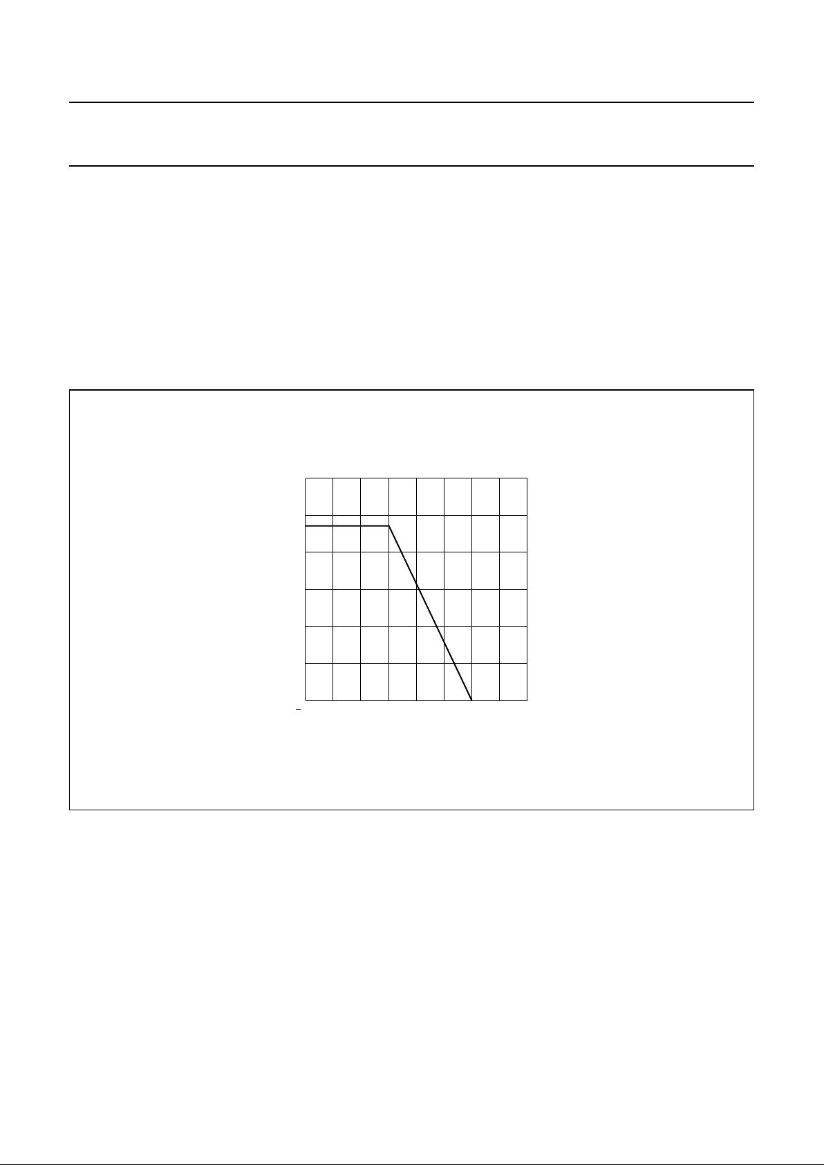
Fig.1 Power derating curve.
handbook, halfpage
50 0 50 150
400
0
MLB950
100
T ( C)
o
amb
P
tot
(mW)
600
200
T
jmaxTamb
–
R
th j-a
--------------------------------- -
100 60–
160
----------------------
0.25 W==
 Loading...