


INTEGRATED CIRCUITS
DATA SH EET
TDA7010T
FM radio circuit
Product specification
File under Integrated Circuits, IC01
September 1983

Philips Semiconductors Product specification
FM radio circuit TDA7010T
GENERAL DESCRIPTION
The TDA7010T is a monolithic integrated circuit for mono FM portable radios, where a minimum on peripheral
components is important (small dimensions and low costs).
The IC has an FLL (Frequency-Locked-Loop) system with an intermediate frequency of 70 kHz. The i.f. selectivity is
obtained by active RC filters. The only function which needs alignment is the resonant circuit for the oscillator, thus
selecting the reception frequency. Spurious reception is avoided by means of a mute circuit, which also eliminates too
noisy input signals. Special precautions are taken to meet the radiation requirements.
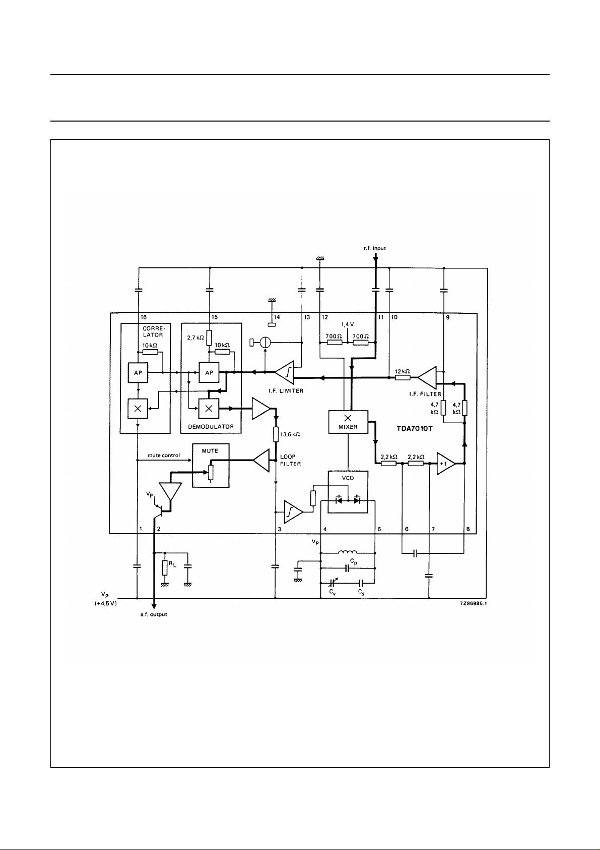
The TDA7010T includes the following functions:
• R.F. input stage
• Mixer
• Local oscillator
• I.F. amplifier/limiter
• Phase demodulator
• Mute detector
• Mute switch
QUICK REFERENCE DATA
Supply voltage range (pin 4) V
Supply current at V
= 4,5 V I
P
R.F. input frequency range f
P
P
rf
2,7 to 10 V
typ. 8 mA
1,5 to 110 MHz
Sensitivity for −3 dB limiting
(e.m.f. voltage)
(source impedance: 75 Ω; mute disabled) EMF typ. 1,5 µV
Signal handling (e.m.f. voltage)
(source impedance: 75 Ω) EMF typ. 200 mV
A.F. output voltage at R
= 22 kΩ V
L
o
typ. 75 mV
PACKAGE OUTLINE
16-lead mini-pack; plastic (SO16; SOT109A); SOT109-1; 1996 July 24.
September 1983 2
Philips Semiconductors Product specification
FM radio circuit TDA7010T
Fig.1 Block diagram.
September 1983 3
Philips Semiconductors Product specification
FM radio circuit TDA7010T
RATINGS
Limiting values in accordance with the Absolute Maximum System (IEC 134)
Supply voltage (pin 4) V
Oscillator voltage (pin 5) V
P
6-5
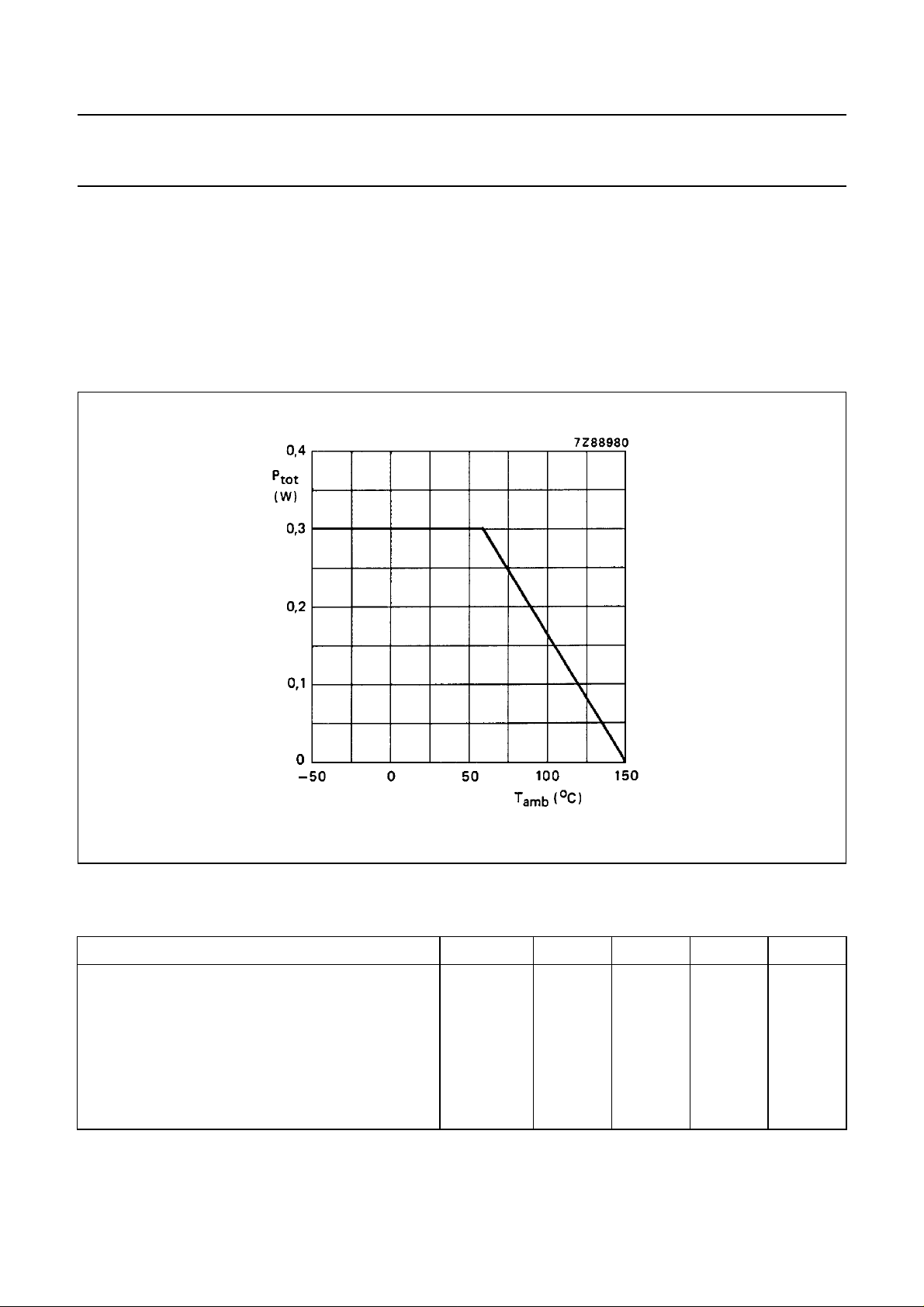
Total power dissipation see derating curve Fig.2
Storage temperature range T
Operating ambient temperature range T
stg
amb
max. 12 V
VP−0,5 to VP+ 0,5 V
−55 to + 150 °C
0 to + 60 °C
Fig.2 Power derating curve.
D.C. CHARACTERISTICS
= 4,5 V; T
V
P
25 °C; measured in Fig.4; unless otherwise specified
amb
PARAMETER SYMBOL MIN. TYP. MAX. UNIT
Supply voltage (pin 4) V
Supply current
at V
= 4,5 V I
P
Oscillator current (pin 5) I
P
5
Voltage at pin 12 V
Output current at pin 2 I
Voltage at pin 2; R
= 22 kΩ V
L
2
September 1983 4
P
12-14
2-14
2,7 4,5 10 V
− 8 − mA
− 280 −µA
− 1,35 − V
− 60 −µA
− 1,3 − V
 Loading...