

Philips TDA4565-V6 Datasheet

DATA SH EET
Product specification
File under Integrated Circuits, IC02
November 1989
INTEGRATED CIRCUITS
TDA4565
Colour transient improvement
circuit

November 1989 2
Philips Semiconductors Product specification
Colour transient improvement circuit TDA4565
GENERAL DESCRIPTION
The TDA4565 is a monolithic integrated circuit for colour transient improvement (CTI) and luminance delay line in gyrator
technique in colour television receivers.
Features
• Colour transient improvement for colour difference signals (R-Y) and (B-Y) with transient detecting-, storage- and
switching stages resulting in high transients of colour difference output signals
• A luminance signal path (Y) which substitutes the conventional Y-delay coil with an integrated Y-delay line
• Switchable delay time from 730 ns to 1000 ns in steps of 90 ns and additional fine adjustment of 50 ns
• Two Y output signals; one of 180 ns less delay
QUICK REFERENCE DATA
Note
1. Delay time is proportional to resistor R
14-18
.
R
14-18
also influences the bandwidth; a value of 1.2 kΩ results in a bandwidth of 5 MHz (typ.).
PACKAGE OUTLINE
18-lead DIL; plastic (SOT102); SOT102-1; 1996 November 27.
PARAMETER CONDITIONS SYMBOL MIN. TYP. MAX. UNIT
Supply voltage (pin 10) V
P
10.8 12 13.2 V
Supply current (pin 10) I
P
− 35 50 mA
Y-signal delay at pin 12 S1 open; R
14-18
= 1.2 kΩ;
(note 1)
V
15-18
= 0 to 2.5 V t
17-12
670 730 790 ns
V
15-18
= 3.5 to 5.5 V t
17-12
760 820 880 ns
V
15-18
= 6.5 to 8.5 V t
17-12
850 910 970 ns
V
15-18
= 9.5 to 12 V t
17-12
940 1000 1060 ns
Y-signal attenuation 0.5 MHz α
Y
0 6.5 8.0 dB
(R-Y) and (B-Y) signal
attenuation α
cd
−10 +1dB
output transient time t
tr
− 100 200 ns
November 1989 3
Philips Semiconductors Product specification
Colour transient improvement circuit TDA4565
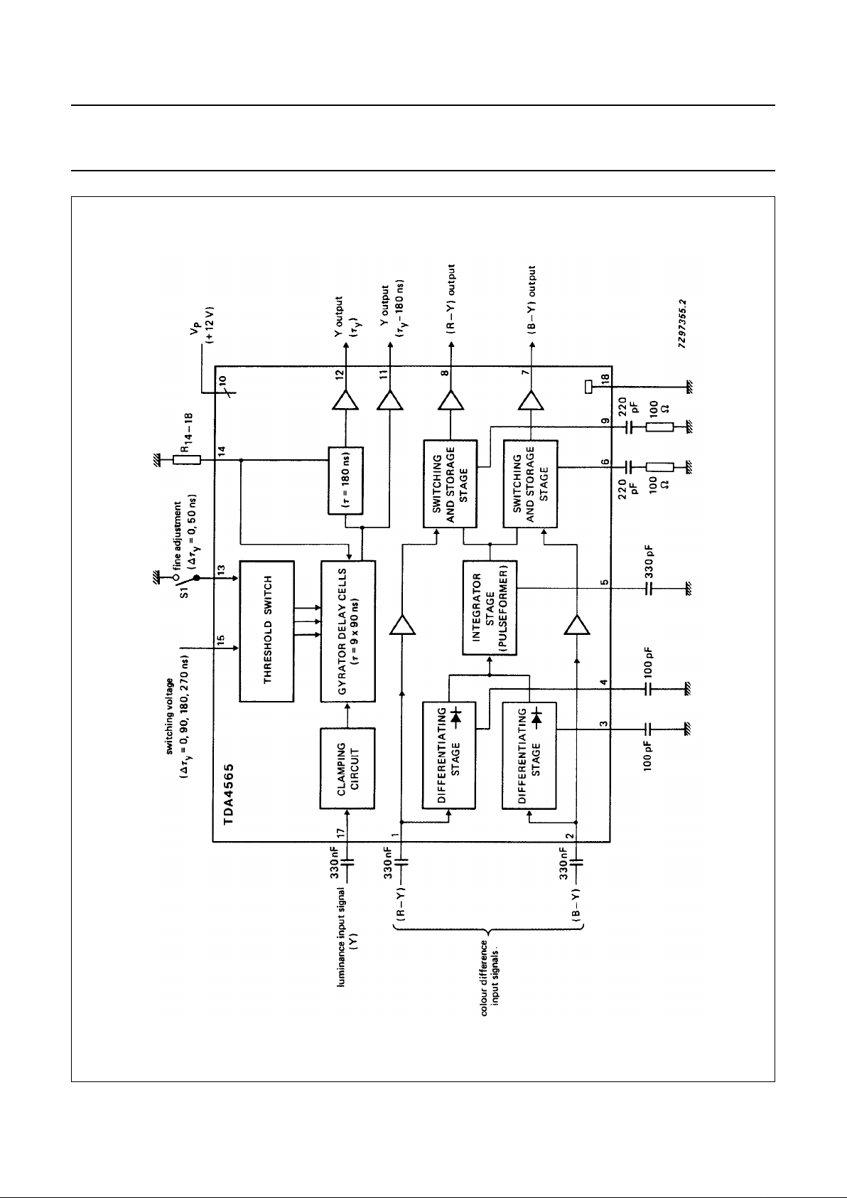
Fig.1 Block diagram.
November 1989 4
Philips Semiconductors Product specification
Colour transient improvement circuit TDA4565
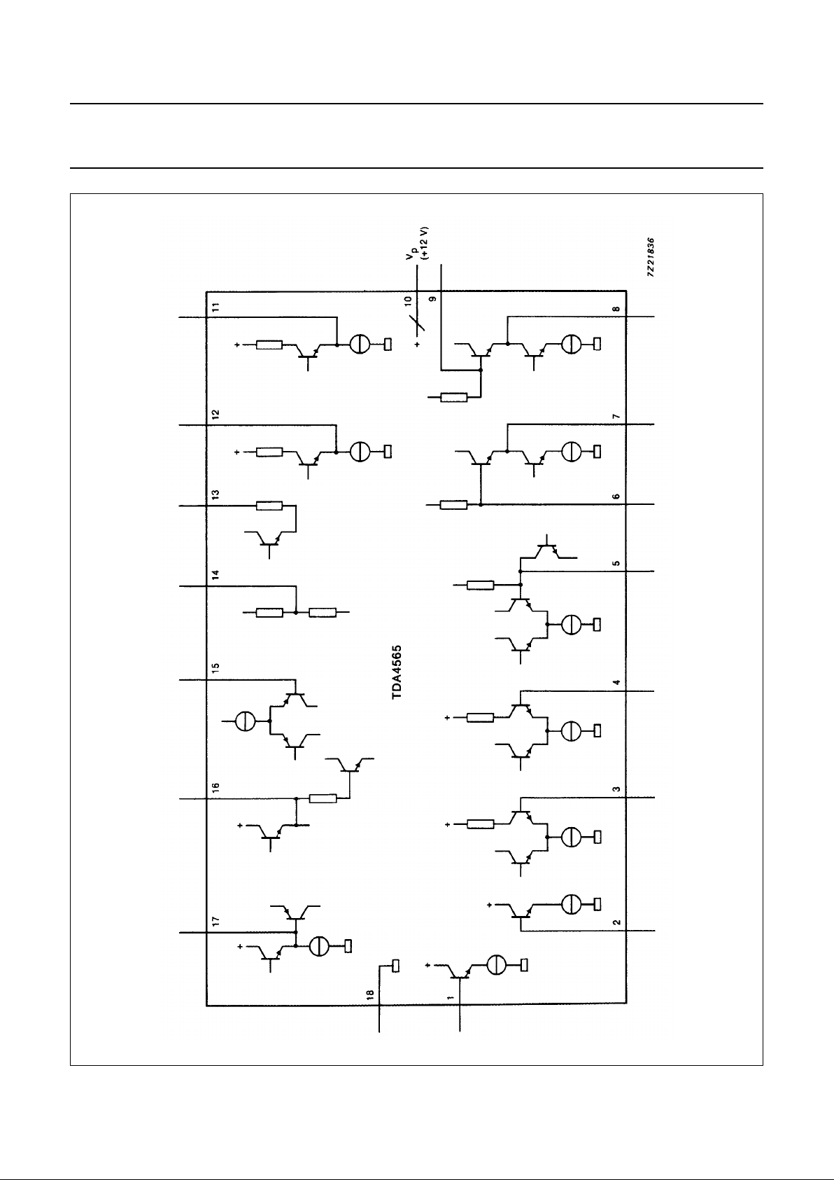
Fig.2 Internal pin circuit diagram.
 Loading...