

Philips TDA3843 Datasheet

INTEGRATED CIRCUITS
DATA SH EET
TDA3843
Sound-IF circuit for TV AM-sound
standard L and L’
Product specification
File under Integrated Circuits, IC02
March 1991

Philips Semiconductors Product specification
Sound-IF circuit for TV AM-sound
TDA3843
standard L and L’
GENERAL DESCRIPTION
The TDA3843 performs the AM-sound demodulation for the L- and L’-standard.
Features
• 5 to 8 V power supply and an alternative 12 V power supply
• Low power consumption (200 mW) at 5 V supply voltage
• New AC-coupled wideband IF-amplifier (high dynamic ranges, less intermodulation)
• In-phase wideband AM demodulator without external reference circuit
• Reduced THD figures even for low AF frequencies (typical 1%)
• Stabilizer circuit for ripple rejection and constant output signals
• All pins are ESD protected
QUICK REFERENCE DATA
PARAMETER SYMBOL MIN. TYP. MAX. UNIT
Supply voltage (pin 14) V
Supply voltage (pin 11) V
Supply current I
Minimum IF input (RMS value) V
IF control range ∆G
AF output signal (RMS value) V
Signal plus weighted-noise to
weighted-noise ratio
(CCIR 468-3) S + W/W 50 56 − dB
P1
P2
11, 14-13
1-16
V
6-13
4.5 5 8.8 V
10.8 12 13.2 V
− 40 48 mA
− 70 100 µV
60 63 − dB
− 550 − mV
PACKAGE OUTLINE
16-lead DIL; plastic (opposite bent leads) (SOT38WBE); SOT38-1; 1996 December 4.
March 1991 2
Philips Semiconductors Product specification
Sound-IF circuit for TV AM-sound
standard L and L’
TDA3843
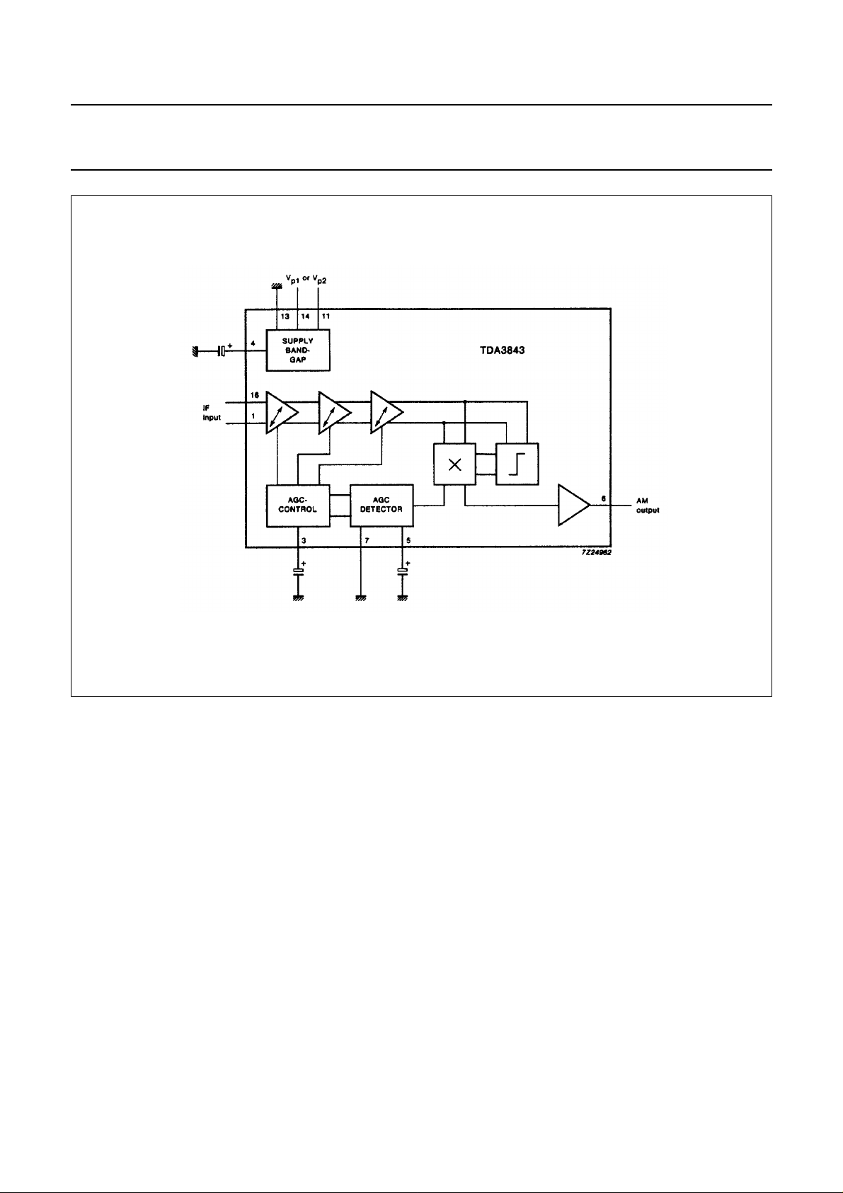
Fig.1 Block diagram.
March 1991 3
 Loading...