

Philips tda3629 DATASHEETS

INTEGRATED CIRCUITS
DATA SH EET
TDA3629
Light position controller
Product specification
File under Integrated Circuits, IC18
1996 Sep 04

Philips Semiconductors Product specification
Light position controller TDA3629
FEATURES
• Low positional error
• Low noise sensitivity due to hysteresis
• Low supply current
• Thermally protected
GENERAL DESCRIPTION
The Light position controller (Leucht Weiten Steller, LWS)
is a monolithic integrated circuit intended to be used in
passenger cars. This device adapts the elevation of the
light beam of the head light of the car to a state defined by
the car driver using a potentiometer on the dashboard.
• Broken wire and short-circuit indication on SET input
• Brake function by short-circuiting the motor
• Hysteresis level set externally.
QUICK REFERENCE DATA
SYMBOL PARAMETER CONDITIONS MIN. TYP. MAX. UNIT
I
P(ss)
supply current, steady state note 1 − − 6 mA
IP− Im supply current, motor active Im < 900 mA − − 80 mA
Vm output voltage Im < 700 mA VP− 2.9− − V
Im output current VP≥ 12.3 V 670 − − mA
I
motor switch on current level VP= 12 V 6 9 12 µA
SET
Note
1. Steady state implies that the motor is not running (Im= 0) and V
= VFB= 0.5VP.
SET
ORDERING INFORMATION
TYPE NUMBER
NAME DESCRIPTION VERSION
TDA3629 DIP8
TDA3629T SO16
PACKAGE
plastic dual in-line package; 8 leads (300 mil)
plastic small outline package; 16 leads; body width 3.9 mm
SOT97-1
SOT109-1
1996 Sep 04 2
Philips Semiconductors Product specification
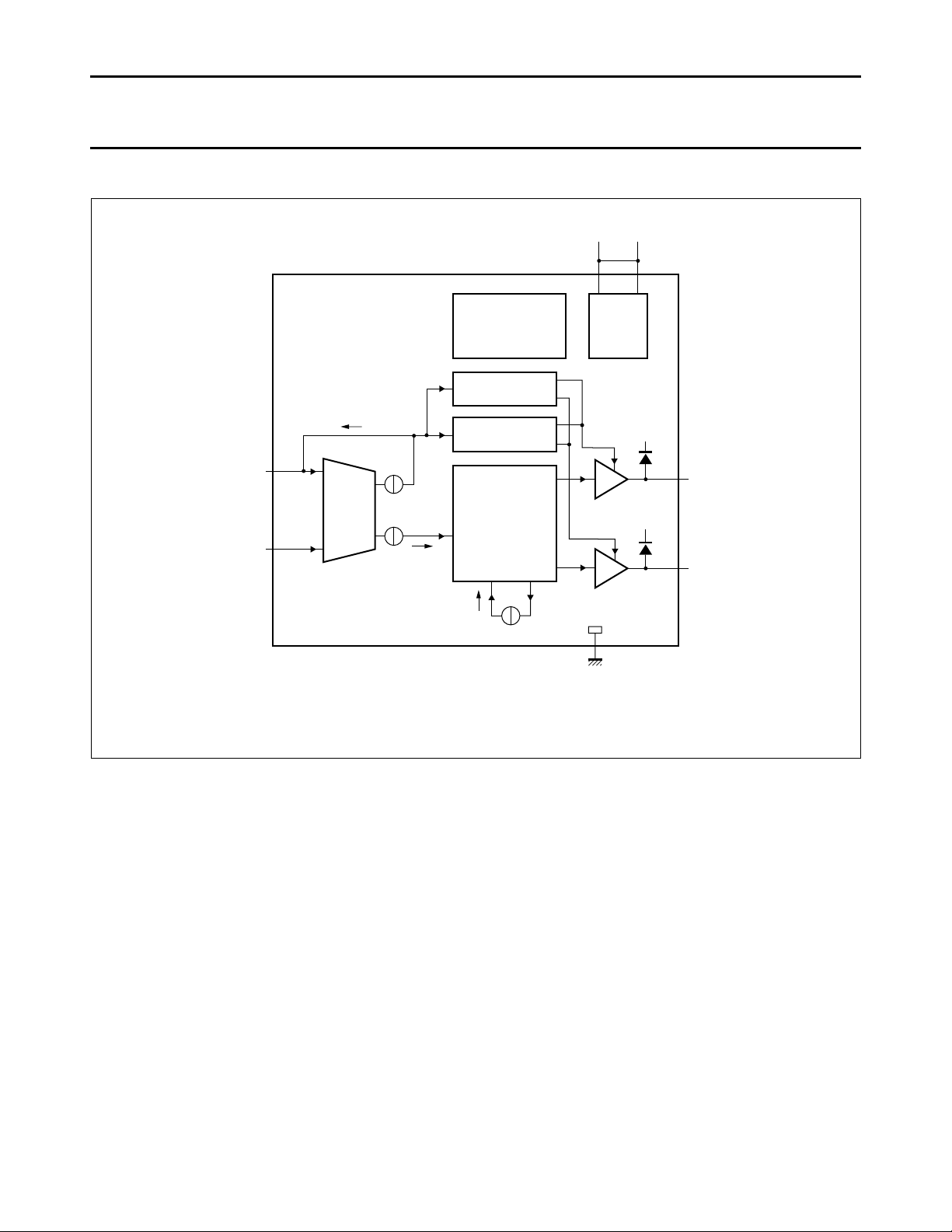
Fig.1 Block diagram.
handbook, full pagewidth
MGE632
INPUT
STAGE
SHORT-CIRCUIT
SUPPLY
BROKEN WIRE
PROTECTION
- OVER VOLTAGE
- UNDER VOLTAGE
- TEMPERATURE
WINDOWS
AND
COMPARATORS
V
P
V
P1
V
P
OUT1
OUTPUT
STAGES
OUT2
SET
7(12)2(5)
8(16)
1(1)
3(6)
5(9)
6(11)
FB
I
SET
I
SET
I
ref
V
P2
TDA3629
Pin numbers in parenthesis represent the TDA3629T.
Light position controller TDA3629
BLOCK DIAGRAM
1996 Sep 04 3

Philips Semiconductors Product specification
Fig.2 Pin configuration TDA3629.
handbook, halfpage
MGE633
TDA3629
1
2
3
4
8
7
6
5
FB
V
P1
OUT1
n.c.
SET
V
P2
OUT2
GND
Fig.3 Pin configuration TDA3629T.
handbook, halfpage
TDA3629T
MGE634
1
2
3
4
5
6
7
8
FB
n.c.
n.c.
n.c.
V
P1
OUT1
n.c.
n.c.
SET
n.c.
n.c.
n.c.
V
P2
OUT2
n.c.
GND
16
15
14
13
12
11
10
9
Light position controller TDA3629
PINNING
SYMBOL
DESCRIPTION
TDA3629 TDA3629T
FB 1 1 feedback input
PIN
V
P1
2 5 supply voltage 1
OUT1 3 6 output 1
(1)
n.c.
4 2 to 4, 7, 8, 10, 13 to 15 not connected
GND 5 9 ground
OUT2 6 11 output 2
V
P2
7 12 supply voltage 2
SET 8 16 set input
Note
1. The pins which are not electrically connected should be connected to a copper area of the printed-circuit board which
is as large as possible to improve heat transfer.
1996 Sep 04 4

Philips Semiconductors Product specification
Fig.4 Conversion gain.
handbook, halfpage
MGE635
100
position
(%)
0
0
V
SET(min)
V
SET(max)
V
SET
(V)
V
b
Light position controller TDA3629
FUNCTIONAL DESCRIPTION
The device is intended to control the elevation of the light
beam of a head light of a passenger car. The driver can
control the elevation of the light beam by rotating a
potentiometer on the dashboard (the setting
potentiometer). The device adapts the elevation of the light
beam by activating the control motor. The elevation of the
head light is fed back to the device by a second
potentiometer (the feedback potentiometer).
This feedback potentiometer is mechanically coupled to
the motor.
The device operates only when the supply voltage is within
certain limits. The device is switched off outside these
boundaries. The under voltage detection detects whether
the supply voltage is below the under voltage threshold.
The motor will not be activated when this occurs, but it
remains short-circuited by the output stages.
The over voltage will switch off the total device when the
supply voltage is higher than the over voltage threshold.
A thermal protection circuit becomes active if the junction
temperature exceeds a value of approximately 160 °C.
This circuit will reduce the motor current, which will result
in a lower dissipation and hence a lower chip temperature.
This condition will only occur when the motor is blocked at
high ambient temperature.
A detection of a broken wire of the slider of the setting
potentiometer is included because it will be connected to
the device by a wire several meters long. This detection
circuit prevents the motor from rotating when the wire is
broken. In this event the brake will remain active.
The protection of V
from rotating when the voltage at the V
to VP circuit prevents the motor
SET
input is above
SET
the threshold value. This can be used to detect whether
the wire from the slider of the setting potentiometer is
short-circuited to the battery line. A protection of V
SET
short-circuited to ground is also present. The motor will be
stopped if V
The shaded areas in Fig.4 represent the parts where the
becomes lower than the threshold level.
SET
short-circuit protection stages are active. Figure 4 shows
that a position of 0 mm can not be reached, neither can a
position of 100%. The minimum position that can be
reached depends on the battery voltage Vb, although the
maximum position does not.
The device is protected against electrical transients which
may occur in an automotive environment. The device will
shut off when positive transients on the battery line occur
(see Figs 7 and 8). The motor will not be short-circuited in
this event. The flyback diodes, illustrated in Fig.1, will
remain present. The state of the output stages at the
moment when the transient starts is preserved by internal
flip-flops. Negative transients on the battery line
(see Figs 7 and 8) will result in a set short-circuited to
ground fault detection, because it will result in a voltage at
the setting input which is below the short-circuited to
ground threshold. The device however discharges the
electrolytic capacitor during these transients. It will stop
functioning when the resulting supply voltage becomes too
low.
1996 Sep 04 5
Philips Semiconductors Product specification
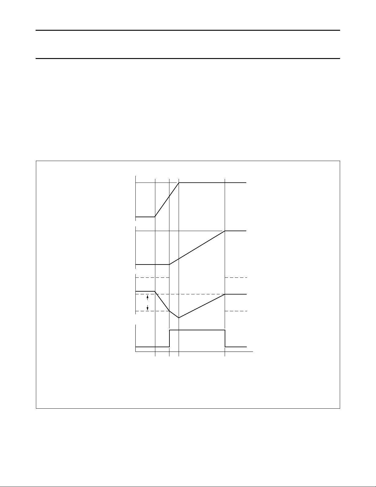
Fig.5 Timing diagram.
handbook, full pagewidth
V
SET
V
FB
I
SET
I
ref
absolute
motor
current
V2
V1
V1
0
0
T1T2T
3
T
4
time
MGE636
V2
Light position controller TDA3629
The timing can be divided into several parts starting from
a steady state (see Fig.5, the starting point, and Fig.10 for
the application diagram): in this state (until T1) a large
reference current is active, indicated by the dotted lines.
When the setting potentiometer is rotated (started at T
and indicated by V
higher than the reference current I
) and the input current I
SET
(at time T2), the motor
ref
SET
1
becomes
will start and the input current will decrease. At the same
time the reference current is switched to a low level.
During rotation of the motor the input current will decrease
until it becomes lower than this low reference current;
this occurs at time T4. At this time the brake becomes
active, the motor will stop and the reference current is set
to the higher value. The brake is realized by
short-circuiting the motor. In general: this system does not
use a linear adaptation strategy but an on-off strategy.
This results in high accuracy and low noise sensitivity.
The brake is active at any time during normal operation
when the motor is not active. The polarity of the feedback
potentiometer should be such that the voltage at the slider
of the feedback potentiometer increases when OUT1 is
high and OUT2 is low.
1996 Sep 04 6

Philips Semiconductors Product specification
Light position controller TDA3629
LIMITING VALUES
In accordance with the Absolute Maximum Rating System (IEC 134). All voltages are defined with respect to ground.
Positive currents flow into the device. Values measured in Fig.10.
SYMBOL PARAMETER CONDITIONS MIN. MAX. UNIT
V
V
V
T
T
T
V
R
t
block
P
n
es
stg
amb
vj
b, tr
L
supply voltage operating 8 18 V
non-operating −0.3 +50 V
voltage on any other pin −0.3 VP+ 0.3 V
electrostatic handling note 1 −3 +3 kV
storage temperature −55 +150 °C
ambient temperature −40 +105 °C
virtual junction temperature note 2 −50 +150 °C
voltage transients on V
b
note 3 −150 +100 V
load resistance note 4 10 − Ω
cumulative blocking time Im = 700 mA − 100 h
Notes
1. Human body model: equivalent to discharging a 100 pF capacitor through a 1.5 kΩ resistor.
2. In accordance with IEC 747-1. An alternative definition of virtual junction temperature Tvj is:
Tvj= T
the allowable combinations of power dissipation Pd and ambient temperature T
amb
+ Pd× R
th vj-amb
, where R
is a fixed value to be used for the calculation of Tvj. The rating for Tvj limits
th vj-amb
. Additional information is given in
amb
section “Thermal aspects” in chapter “Test and application information”.
3. Wave forms illustrated in Figs 7 and 8 applied to the application diagram, Fig.10.
4. Vb= 13 V; T
= 25 °C; duration 50 ms maximum; non repetitive.
amb
THERMAL CHARACTERISTICS
In accordance with IEC 747-1.
SYMBOL PARAMETER VALUE UNIT
R
th vj-amb
thermal resistance from junction to ambient in free air
TDA3629 100 K/W
TDA3629T 105 K/W
1996 Sep 04 7

Philips Semiconductors Product specification
Light position controller TDA3629
CHARACTERISTICS
VP= 12 V; RL= 14 Ω. All voltages are defined with respect to ground. Positive currents flow into the device.
Values measured in Fig.10 with R
SYMBOL PARAMETER CONDITIONS MIN. TYP. MAX. UNIT
Supply
V
P(min)
V
P(max)
I
P(ss)
under voltage threshold 6 − 8 V
over voltage threshold T
supply current, steady state note 1 − − 6 mA
IP− Im supply current, motor active Im < 400 mA; note 2 − − 40 mA
Setting input (SET)
V
SET
I
SET
V
SET(sc)
operating voltage 1.5 − 0.95VPV
input current R
wire short-circuited to ground
threshold
wire short-circuited to battery
threshold
∆V
SET
broken ground set pull-up note 3 − − 160 mV
Feedback input (FB)
V
FB
I
FB(max)
voltage 1.5 − 0.95VPV
maximum input current RFB> 20 kΩ −250 − +250 µA
Motor outputs
V
output voltage Im < 700 mA;
m
Im output current VP≥ 12.3 V;
= RFB= 20 kΩ; unless otherwise specified.
SET
= 25 °C 18 − 22 V
amb
T
= −40 to +105 °C 17.5 − 22.8 V
amb
Im < 900 mA; note 2 − − 80 mA
> 20 kΩ −250 − +250 µA
SET
output stages switched off − − 1 V
output stages switched off V
T
= 25 °C; note 2
amb
Im < 700 mA;
T
= −40 to +105 °C;
amb
note 2
T
= 25 °C; note 2
amb
VP≥ 12.3 V;
T
= −40 to +105 °C;
amb
note 2
P
− − V
VP− 2.9 − − V
VP− 3.4 − − V
670 − − mA
635 − − mA
Reference current
I
motor switch-on level VP= 12 V 6 9 12 µA
SET
VP= 18 V 9 13 17 µA
motor switch-off level − 2.5 − µA
1996 Sep 04 8

Philips Semiconductors Product specification
Fig.6 Conditions for the test of note 3.
The 170 Ω, 830 Ω and 390 Ω resistors form the setting potentiometer in its worst case position. The given situation (combination of Vb, R
SET
and the
position of the set potentiometer) forms the worst case situation. The given maximum of ∆V
SET
guarantees that any other module, connected to the
same set potentiometer, will not start to activate its motor, when its motor switch-on level is higher than 0.01V
b
(R
SET
≥ 20 kΩ).
handbook, halfpage
MGE637
R
SET
V
SET, br
+V
b
battery
ground
830 Ω
390 Ω
170 Ω
REMAINDER OF
MODULE
ground wire not connected
+
−
Light position controller TDA3629
Notes to the characteristics
1. Steady state implies that the motor is not running (Im= 0) and V
2. This is only valid when the temperature protection is not active.
3. ∆V
is the difference in voltage on the set potentiometer between the situation when the ground wire is interrupted
SET
(V
) and voltage on the set potentiometer during normal operation (when V
SET, br
The conditions for this test are:
R
= 20 kΩ; Vb= 16 V; ∆V
SET
SET
= V
− 2.72 V; see Fig.6.
SET, br
= VFB= 0.5VP.
SET
= 0.17Vb= 2.72 V).
SET
QUALITY SPECIFICATION
The quality of this device is in accordance with
found in the
1996 Sep 04 9
“Quality reference Handbook”
“SNW-FQ-611 part E”
. The numbers of the quality specification can be
. The handbook can be ordered using the code 9397 750 00192.
 Loading...