

Philips TDA1576 Datasheet

INTEGRATED CIRCUITS
DATA SH EET
TDA1576
FM/IF amplifier/demodulator circuit
Product specification
Supersedes data of March 1985
File under Integrated Circuits, IC01
1998 Nov 18

Philips Semiconductors Product specification
FM/IF amplifier/demodulator circuit TDA1576
FEATURES
• Symmetrical limiting IF amplifier
• Symmetrical quadrature demodulator
• Internal muting circuit
GENERAL DESCRIPTION
The TDA1576 is a monolithic integrated FM/IF amplifier
circuit for use in mono and stereo FM-receivers of car
radios or home sets.
• Symmetrical AFC output
• Field strength indication output
• Detune detector
• Reference voltage output
• Electronic smoothing of the supply voltage
• Standby on/off switching circuit.
QUICK REFERENCE DATA
f
= 10.7 MHz; ∆f=±22.5 kHz; fm= 400 Hz; QL= 20; 50 µs de-emphasis.
o
SYMBOL PARAMETER CONDITIONS MIN. TYP. MAX. UNIT
V
P
I
P
V
iIF(rms)
V
oAF(rms)
supply voltage (pin 1) 7.5 − 20 V
supply current VP= 8.5 V − 16 − mA
V
=15V − 18 − mA
P
input sensitivity (RMS value) −3 dB before limiting − 22 −µV
SN+
-------------N
SN+
-------------N
=26dB
=46dB
− 8 −µV
− 35 −µV
AF output voltage (RMS value) VP= 8.5 V − 67 − mV
V
=15V − 135 − mV
P
THD total harmonic distortion
single tuned circuit − 0.1 − %
two tuned circuits − 0.02 − %
SN+
-------------N
signal plus noise-to-noise ratio V
> 1 mV (RMS);
iIF
VP= 8.5 V
> 1 mV (RMS);
V
iIF
− 76 − dB
− 80 − dB
VP=15V
α
AM
∆f
i
∆V
i
I
L
T
amb
AM suppression − 50 − dB
AFC offset drift −±3±6 kHz
field strength indication − 90 − dB
permissible indicator load current −−2mA
operating ambient temperature −30 − +80 °C
ORDERING INFORMATION
TYPE
NUMBER
NAME DESCRIPTION VERSION
PACKAGE
TDA1576 DIP18 plastic dual in-line package; 18 leads (300 mil) SOT102-1
1998 Nov 18 2
This text is here in white to force landscape pages to be rotated correctly when browsing through the pdf in the Acrobat reader.This text is here in
o
_white to force landscape pages to be rotated correctly when browsing through the pdf in the Acrobat reader.This text is here inThis text is here in
white to force landscape pages to be rotated correctly when browsing through the pdf in the Acrobat reader. white to force landscape pages to be ...
1998 Nov 18 3
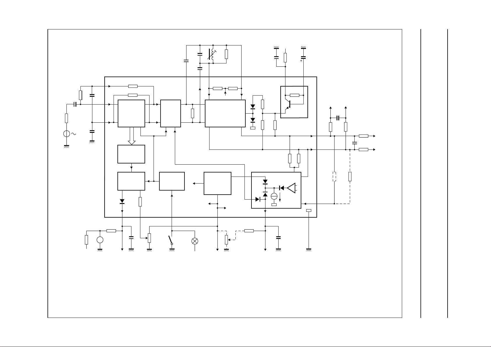
560
pF
33
pF
33
pF
V
17
FB1
0.1
R
S
0.1 µF
R
S
V
S
µF
0.1
µF
V
15
ilF
V
16
FB2
V
iIF
25 kΩ
25 kΩ
4-STAGE
LIMITER/
AMPLIFIER
LEVEL
DETECTOR
INDICATOR
DRIVER
20 kΩ
MUTING
STANDBY
SWITCH
3
250
Ω
TDA1576
4 V
(6 VBE)
L
RES2IF2IF1
76
15 kΩ
QUADRATURE
DEMODULATOR
INTERNAL
POWER
SUPPLY
(2)
5.3 V
(185 VT)
k, full pagewidth
750
Ω
4
15 kΩ
1.7 V
RES1
0.1 µF
5.5
kΩ
3.7
kΩ
+
12
3.7
kΩ
DETUNE
DETECTOR
I
11 =
0.5 mA
10 Ω
V
P
(15 V)
8.3 kΩ
G
47 µF
C
PS
8
V
oAF1
9
V
oAF2
V
10
i(det)
AFC
voltage
+−
Z
Z
8-10
(180
(240
kΩ)
kΩ)
(3.3 kΩ)
C
8-9
9-10
(1)
BLOCK DIAGRAM
Philips Semiconductors Product specification
FM/IF amplifier/demodulator circuit TDA1576
V
oAF
3.6 kΩ
1 mA
A
(AM)
field
strength
indicator
(1) For 50 µs de-emphasis: C
13 14
V
level output
for
field strength
= 6.8nF; for stereo operation C
8−9
F
1
nF
zero adjustment
of field strength
V
F0
indicator
(25 kΩ)
5121118
FM
on
+
(<23 V)
=56pF.
8−9
V
reference
voltage
ref
220 kΩ
10 kΩ
detune
voltage
V
o(det)
GNDFMON
0.47 µF
MGE456
(2) L = 0.38 µH; Qo= 70; QL= 20; adjusted to minimum 2nd harmonic distortion (d2); at Vi= 1 mV; coil: 6 turns CuL (0.25 mm) on coil former KAN (C).
Fig.1 Block diagram and test circuit.
Philips Semiconductors Product specification
FM/IF amplifier/demodulator circuit TDA1576
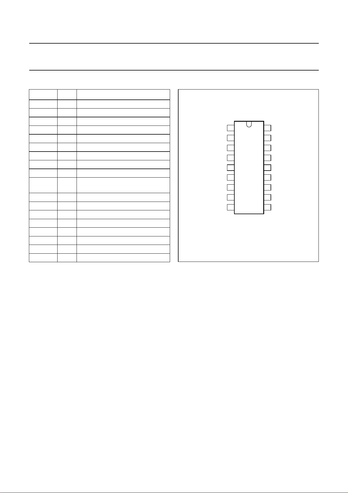
PINNING
SYMBOL PIN DESCRIPTION
V
P
C
PS
IF1 3 IF signal to resonant circuit
RES1 4 resonant circuit input 1
FMON 5 FM-ON, standby switch
RES2 6 resonant circuit input 2
IF2 7 IF signal to resonant circuit
V
oAF1
V
oAF2
V
i(det)
V
o(det)
V
ref
V
F
V
F0
V
iIF
V
FB2
V
FB1
GND 18 ground (0 V)
1 positive supply voltage
2 smoothing capacitor of power supply
8 AF output voltage 1 (0° phase)
9 AF output voltage 2 (180° phase)
10 detune detector input voltage for
external audio reference
11 detune detector output voltage
12 reference voltage output
13 level output for field strength
14 zero adjust voltage for field strength
15 FM/IF input signal voltage
16 DC feedback 2
17 DC feedback 1
handbook, halfpage
V
1
P
C
2
PS
IF1
3
RES1
4
FMON
5
TDA1576
RES2
6
7
IF2
V
8
oAF1
V
9
oAF2
MBH286
Fig.2 Pin configuration.
18
GND
17
V
FB1
16
V
FB2
V
15
ilF
V
14
F0
V
13
F
V
12
ref
V
11
o(det)
V
10
i(det)
1998 Nov 18 4

Philips Semiconductors Product specification
FM/IF amplifier/demodulator circuit TDA1576
LIMITING VALUES
In accordance with the Absolute Maximum Rating System (IEC 134).
SYMBOL PARAMETER MIN. MAX. UNIT
V
P
V
2
V
5, 14
V
12
V
13
P
tot
T
stg
T
amb
THERMAL CHARACTERISTICS
SYMBOL PARAMETER VALUE UNIT
R
th j-a
supply voltage (pin 1) 0 23 V
voltage on pin 2 0 V
P
V
voltage on pins 5 and 14 0 23 V
voltage on pin 12 0 7 V
voltage on pin 13 0 6 V
total power dissipation 0 800 mW
storage temperature −55 +150 °C
operating ambient temperature −30 +80 °C
thermal resistance from junction to ambient in free air 80 K/W
1998 Nov 18 5
 Loading...