

Philips TCS1.0L LA Service Manual

Color TV Chassis
MG8
TCS1.0L
LA
MG8
I_17930_000.eps
240408
Contents Page Contents Page
1. Technical Specifications, Connections, and Chassis
Overview 2
2. Safety Instructions, Warnings, and Notes 5
3. Directions for Use 6
4. Mechanical Instructions 7
5. Service Modes, Error Codes, and Fault Finding 13
6. Block Diagrams, Test Point Overview, and
Waveforms
Wiring Diagram of Connector for MS19-PH 19" 21
Wiring Diagram of Connector for MS19-PH 26" 22
Block Diagram MS19P Chipset 23
I2C overview 24
7. Circuit Diagrams and PWB Layouts Diagram PWB
Main Power Supply (19") (A) 25 26
Main Power Supply (26") (A1) 27 28-29
Standby Power Supply (26") (A2) 30 31-32
SSB: Control (B01) 33 42-43
SSB: DC - DC (B02) 34 42-43
SSB: MST9E19A Controller (B03) 35 42-43
SSB: HDMI Interface (B04) 36 42-43
SSB: VGA Interface (B05) 37 42-43
SSB: Cinch (B06) 38 42-43
SSB: Tuner (B07) 39 42-43
SSB: Audio Amplifier (B08) 40 42-43
SSB: LVDS Interface (B09) 41 42-43
Keyboard Control Panel (E) 44 44
Inverter Panel (I) 45 46
IR LED Panel (J) 47 47
8. Alignments 49
9. Circuit Descriptions, Abbreviation List, and IC Data
Sheets 50
Abbreviation List 51
IC Data Sheets 53
10. Spare Parts List & CTN Overview 57
11. Revision List 57
©
Copyright 2008 Koninklijke Philips Electronics N.V.
All rights reserved. No part of this publication may be reproduced, stored in a
retrieval system or transmitted, in any form or by any means, electronic,
mechanical, photocopying, or otherwise without the prior permission of Philips.
Published by JY 0866 BU TV Consumer Care Printed in the Netherlands Subject to modification EN 3122 785 18130

EN 2 TCS1.0L LA1.
Technical Specifications, Connections, and Chassis Overview
1. Technical Specifications, Connections, and Chassis Overview
Index of this chapter:
1.1 Technical Specifications
1.2 Connection Overview
1.3 Chassis Overview
Notes:
• Figures can deviate due to the different set executions.
• Specifications are indicative (subject to change).
1.1 Technical Specifications
1.1.1 Vision
Display type : LCD
Screen size : 19" (51 cm), 16 : 9
Resolution (H × V pixels) : 1440 × 900 (19")
Light output (cd/m
Typ. response time (ms) : 8
Viewing angle (H × V degrees) : 170 × 160 (19")
Tuning system : NTSC M, PAL N/M
Video playback : NTSC, PAL (all
Tuner bands : UHF, VHF, S & Hyper
Supported Computer Formats
60 Hz : 640 × 480
60 Hz : 800 × 600
60 Hz : 1024 × 768
60 Hz : 1280 × 1024 (26")
50 Hz, 75 Hz : 1440 × 900 (19")
Supported Video Formats
60 Hz : 480i
60 Hz : 480p
50 Hz : 576i
50 Hz : 576p
50 Hz, 60 Hz : 720p
50 Hz, 60 Hz : 1080i
2
) : 300 (19")
: 26" (66 cm), 16 : 9
: 1366 × 768 (26")
: 450 (26")
: 160 × 160 (26")
versions)
1.1.3 Miscellaneous
Power supply
- Mains voltage (V
- Mains frequency (Hz) : 50, 60
Power consumption (W) : 50 (19")
Stand-by (W) : < 0.3
Dimensions (W × H × D in mm) : 473 × 353 × 69 (19")
Weight (kg) : 4.2 (19")
) : 100 to 240
AC
: 80 (26")
: 671 × 458 × 90 (26")
: 7.7 (26")
1.1.2 Sound
Sound systems : Mono
Maximum power (W) : 2 × 3 (19")
:Stereo
: SAP
:2 × 5 (26")

Technical Specifications, Connections, and Chassis Overview
1.2 Connection Overview
1
1
EN 3TCS1.0L LA 1.
10
10
9
9
8
8
34 56 7
2
2
34 56 7
I_18130_001.eps
160608
Note: The following connector color abbreviations are used
(acc. to DIN/IEC 757): Bk= Black, Bu= Blue, Gn= Green, Gy=
Grey, Rd= Red, Wh= White, and Ye= Yellow.
1.2.1 Rear Connections
1 - HDMI: Digital Video, Digital Audio - In
19
18 2
1
E_06532_017.eps
250505
Figure 1-2 HDMI (type A) connector
1 -D2+ Data channel j
2-Shield Gnd H
3 -D2- Data channel j
4 -D1+ Data channel j
5-Shield Gnd H
6 -D1- Data channel j
7 -D0+ Data channel j
8-Shield Gnd H
9 -D0- Data channel j
10 - CLK+ Data channel j
11 - Shield Gnd H
12 - CLK- Data channel j
13 - n.c.
14 - n.c.
15 - DDC_SCL DDC clock j
16 - DDC_SDA DDC data jk
17 - Ground Gnd H
18 - +5V j
19 - HPD Hot Plug Detect j
20 - Ground Gnd H
2 - VGA AUDIO: Mini Jack: VGA Audio - In
Bk - Audio L/R 0.5 V
/ 10 kΩ jq
RMS
Figure 1-1 Rear and side I/O connections
3 - VGA PC: Video RGB - In and Service UART
1 -Video Red 0.7 V
2 -Video Green 0.7 V
3 -Video Blue 0.7 V
4-n.c.
5 -Ground Gnd H
6 -Ground Red Gnd H
7 -Ground Green Gnd H
8 -Ground Blue Gnd H
9 -+5V_dc +5 V j
10 - Ground Sync Gnd H
11 - n.c.
12 - DDC_SDA DDC data jk
13 - H-sync 0 - 5 V j
14 - V-sync 0 - 5 V j
15 - DDC_SCL DDC clock j
4 - Cinch: Video YPbPr - In
Gn - Video Y 1 V
Bu - Video Pb 0.7 V
Rd - Video Pr 0.7 V
Wh - Audio L 0.5 V
Rd - Audio R 0.5 V
5 - AV1: Cinch: Video CVBS - In, Audio - In
Ye - Video CVBS 1 V
Wh - Audio L 0.5 V
Rd - Audio R 0.5 V
6 - Aerial - In
- - F-type (US) Coax, 75 Ω D
1
6
11
5
10
15
E_06532_002.eps
050404
Figure 1-3 VGA Connector
/ 75 Ω j
PP
/ 75 Ω j
PP
/ 75 Ω j
PP
/ 75 Ω jq
PP
/ 75 Ω jq
PP
/ 75 Ω jq
PP
/ 10 kΩ jq
RMS
/ 10 kΩ jq
RMS
/ 75 Ω jq
PP
/ 10 kΩ jq
RMS
/ 10 kΩ jq
RMS
7 - Service Connector (ComPair)
1 -SDA-S I
2 -SCL-S I
2
C Data (0 - 5 V) jk
2
C Clock (0 - 5 V) j
3 -Ground Gnd H
EN 4 TCS1.0L LA1.
Technical Specifications, Connections, and Chassis Overview
1.2.2 Side connections
8 - Cinch: Video CVBS - In, Audio - In
Ye - Video CVBS 1 V
Wh - Audio L 0.5 V
Rd - Audio R 0.5 V
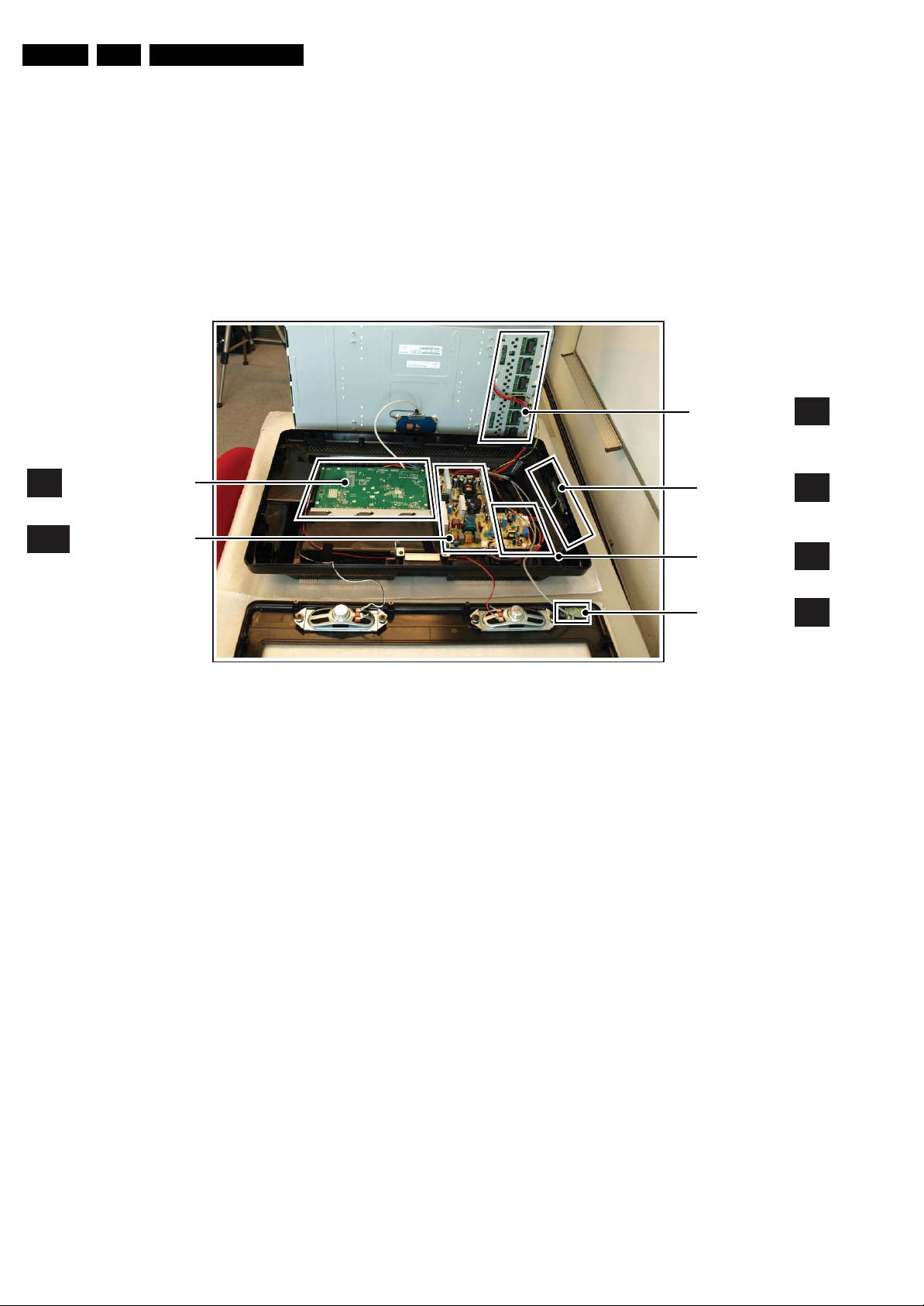
1.3 Chassis Overview
SMALL SIGNAL BOARD
B
A(1)
MAIN POWER SUPPLY
/ 75 Ω jq
PP
/ 10 kΩ jq
RMS
/ 10 kΩ jq
RMS
9 - S-Video (Hosiden): Video Y/C - In
1 -Ground Y Gnd H
2 -Ground C Gnd H
3 -Video Y 1 V
4 -Video C 0.3 V
10 - Mini Jack: Audio Head phone - Out
Bk - Head phone 32 - 600 Ω / 10 mW ot
/ 75 Ω j
PP
P / 75 Ω j
PP
INVERTER PANEL
(OPTONAL)
KEYBOARD
CONTROL PANEL
STANDBY POWER
SUPPLY UNIT
(OPTIONAL)
I
E
A2
Figure 1-4 PWB/CBA locations
IR LED PANEL
I_17950_002.eps
J
080508

Safety Instructions, Warnings, and Notes
2. Safety Instructions, Warnings, and Notes
EN 5TCS1.0L LA 2.
Index of this chapter:
2.1 Safety Instructions
2.2 Warnings
2.3 Notes
2.1 Safety Instructions
Safety regulations require the following during a repair:
• Connect the set to the Mains/AC Power via an isolation
transformer (> 800 VA).
• Replace safety components, indicated by the symbol h,
only by components identical to the original ones. Any
other component substitution (other than original type) may
increase risk of fire or electrical shock hazard.
Safety regulations require that after a repair, the set must be
returned in its original condition. Pay in particular attention to
the following points:
• Route the wire trees correctly and fix them with the
mounted cable clamps.
• Check the insulation of the Mains/AC Power lead for
external damage.
• Check the strain relief of the Mains/AC Power cord for
proper function.
• Check the electrical DC resistance between the Mains/AC
Power plug and the secondary side (only for sets that have
a Mains/AC Power isolated power supply):
1. Unplug the Mains/AC Power cord and connect a wire
between the two pins of the Mains/AC Power plug.
2. Set the Mains/AC Power switch to the “on” position
(keep the Mains/AC Power cord unplugged!).
3. Measure the resistance value between the pins of the
Mains/AC Power plug and the metal shielding of the
tuner or the aerial connection on the set. The reading
should be between 4.5 MΩ and 12 MΩ.
4. Switch “off” the set, and remove the wire between the
two pins of the Mains/AC Power plug.
• Check the cabinet for defects, to prevent touching of any
inner parts by the customer.
2.2 Warnings
• All ICs and many other semiconductors are susceptible to
electrostatic discharges (ESD w). Careless handling
during repair can reduce life drastically. Make sure that,
during repair, you are connected with the same potential as
the mass of the set by a wristband with resistance. Keep
components and tools also at this same potential.
• Be careful during measurements in the high voltage
section.
• Never replace modules or other components while the unit
is switched “on”.
• When you align the set, use plastic rather than metal tools.
This will prevent any short circuits and the danger of a
circuit becoming unstable.
2.3 Notes
2.3.1 General
• Measure the voltages and waveforms with regard to the
chassis (= tuner) ground (H), or hot ground (I), depending
on the tested area of circuitry. The voltages and waveforms
shown in the diagrams are indicative. Measure them in the
Service Default Mode (see chapter 5) with a color bar
signal and stereo sound (L: 3 kHz, R: 1 kHz unless stated
otherwise) and picture carrier at 475.25 MHz for PAL, or
61.25 MHz for NTSC (channel 3).
• Where necessary, measure the waveforms and voltages
with (D) and without (E) aerial signal. Measure the
voltages in the power supply section both in normal
operation (G) and in stand-by (F). These values are
indicated by means of the appropriate symbols.
2.3.2 Schematic Notes
• All resistor values are in ohms, and the value multiplier is
often used to indicate the decimal point location (e.g. 2K2
indicates 2.2 kΩ).
• Resistor values with no multiplier may be indicated with
either an “E” or an “R” (e.g. 220E or 220R indicates 220 Ω).
• All capacitor values are given in micro-farads (μ=× 10
nano-farads (n =× 10
• Capacitor values may also use the value multiplier as the
decimal point indication (e.g. 2p2 indicates 2.2 pF).
• An “asterisk” (*) indicates component usage varies. Refer
to the diversity tables for the correct values.
• The correct component values are listed in the Spare Parts
List. Therefore, always check this list when there is any
doubt.
2.3.3 BGA (Ball Grid Array) ICs
Introduction
For more information on how to handle BGA devices, visit this
URL: www.atyourservice.ce.philips.com (needs subscription,
not available for all regions). After log-in, select “Magazine”,
then go to “Repair downloads”. Here you will find Information
on how to deal with BGA-ICs.
BGA Temperature Profiles
For BGA-ICs, you must use the correct temperature-profile,
which is coupled to the 12NC. For an overview of these profiles,
visit the website www.atyourservice.ce.philips.com (needs
subscription, but is not available for all regions)
You will find this and more technical information within the
“Magazine”, chapter “Repair downloads”.
For additional questions please contact your local repair help
desk.
2.3.4 Lead-free Soldering
Due to lead-free technology some rules have to be respected
by the workshop during a repair:
• Use only lead-free soldering tin Philips SAC305 with order
code 0622 149 00106. If lead-free solder paste is required,
please contact the manufacturer of your soldering
equipment. In general, use of solder paste within
workshops should be avoided because paste is not easy to
store and to handle.
• Use only adequate solder tools applicable for lead-free
soldering tin. The solder tool must be able:
– To reach a solder-tip temperature of at least 400°C.
– To stabilize the adjusted temperature at the solder-tip.
– To exchange solder-tips for different applications.
• Adjust your solder tool so that a temperature of around
360°C - 380°C is reached and stabilized at the solder joint.
Heating time of the solder-joint should not exceed ~ 4 sec.
Avoid temperatures above 400°C, otherwise wear-out of
tips will increase drastically and flux-fluid will be destroyed.
To avoid wear-out of tips, switch “off” unused equipment or
reduce heat.
• Mix of lead-free soldering tin/parts with leaded soldering
tin/parts is possible but PHILIPS recommends strongly to
avoid mixed regimes. If this cannot be avoided, carefully
clear the solder-joint from old tin and re-solder with new tin.
-9
), or pico-farads (p =× 10
-12
-6
),
).
EN 6 TCS1.0L LA3.
2.3.5 Alternative BOM identification
The third digit in the serial number (example:
AG2B0335000001) indicates the number of the alternative
B.O.M. (Bill Of Materials) that has been used for producing the
specific TV set. In general, it is possible that the same TV
model on the market is produced with e.g. two different types
of displays, coming from two different suppliers. This will then
result in sets which have the same CTN (Commercial Type
Number; e.g. 28PW9515/12) but which have a different B.O.M.
number.
By looking at the third digit of the serial number, one can
identify which B.O.M. is used for the TV set he is working with.
If the third digit of the serial number contains the number “1”
(example: AG1B033500001), then the TV set has been
manufactured according to B.O.M. number 1. If the third digit is
a “2” (example: AG2B0335000001), then the set has been
produced according to B.O.M. no. 2. This is important for
ordering the correct spare parts!
For the third digit, the numbers 1...9 and the characters A...Z
can be used, so in total: 9 plus 26= 35 different B.O.M.s can be
indicated by the third digit of the serial number.
Identification: The bottom line of a type plate gives a 14-digit
serial number. Digits 1 and 2 refer to the production centre (e.g.
AG is Bruges), digit 3 refers to the B.O.M. code, digit 4 refers
to the Service version change code, digits 5 and 6 refer to the
production year, and digits 7 and 8 refer to production week (in
example below it is 2006 week 17). The 6 last digits contain the
serial number.
Directions for Use
MODEL :
PROD.NO:
2.3.6 Board Level Repair (BLR) or Component Level Repair (CLR)
If a board is defective, consult your repair procedure to decide
if the board has to be exchanged or if it should be repaired on
component level.
If your repair procedure says the board should be exchanged
completely, do not solder on the defective board. Otherwise, it
cannot be returned to the O.E.M. supplier for back charging!
2.3.7 Practical Service Precautions
• It makes sense to avoid exposure to electrical shock.
• Always respect voltages. While some may not be
32PF9968/10
AG 1A0617 000001
Figure 2-1 Serial number (example)
While some sources are expected to have a possible
dangerous impact, others of quite high potential are of
limited current and are sometimes held in less regard.
dangerous in themselves, they can cause unexpected
reactions that are best avoided. Before reaching into a
powered TV set, it is best to test the high voltage insulation.
It is easy to do, and is a good service precaution.
MADE IN BELGIUM
220-240V 50/60Hz
VHF+S+H+UHF
S
~
BJ3.0E LA
E_06532_024.eps
128W
260308
3. Directions for Use
You can download this information from the following websites:
http://www.philips.com/support
http://www.p4c.philips.com

4. Mechanical Instructions
Mechanical Instructions
EN 7TCS1.0L LA 4.
Index of this chapter:
4.1 Cable Dressing
4.2 Service Positions
4.3 Assy/Panel Removal
4.4 Set Re-assembly
4.1 Cable Dressing
Notes:
• Figures below can deviate slightly from the actual situation,
due to the different set executions.
• Follow the disassemble instructions in described order.
They apply mostly to the 26" model unless otherwise
specified, but the described method is comparable for the
other screen sizes.
Figure 4-1 Cable dressing (19" model)
I_17950_003.eps
080508
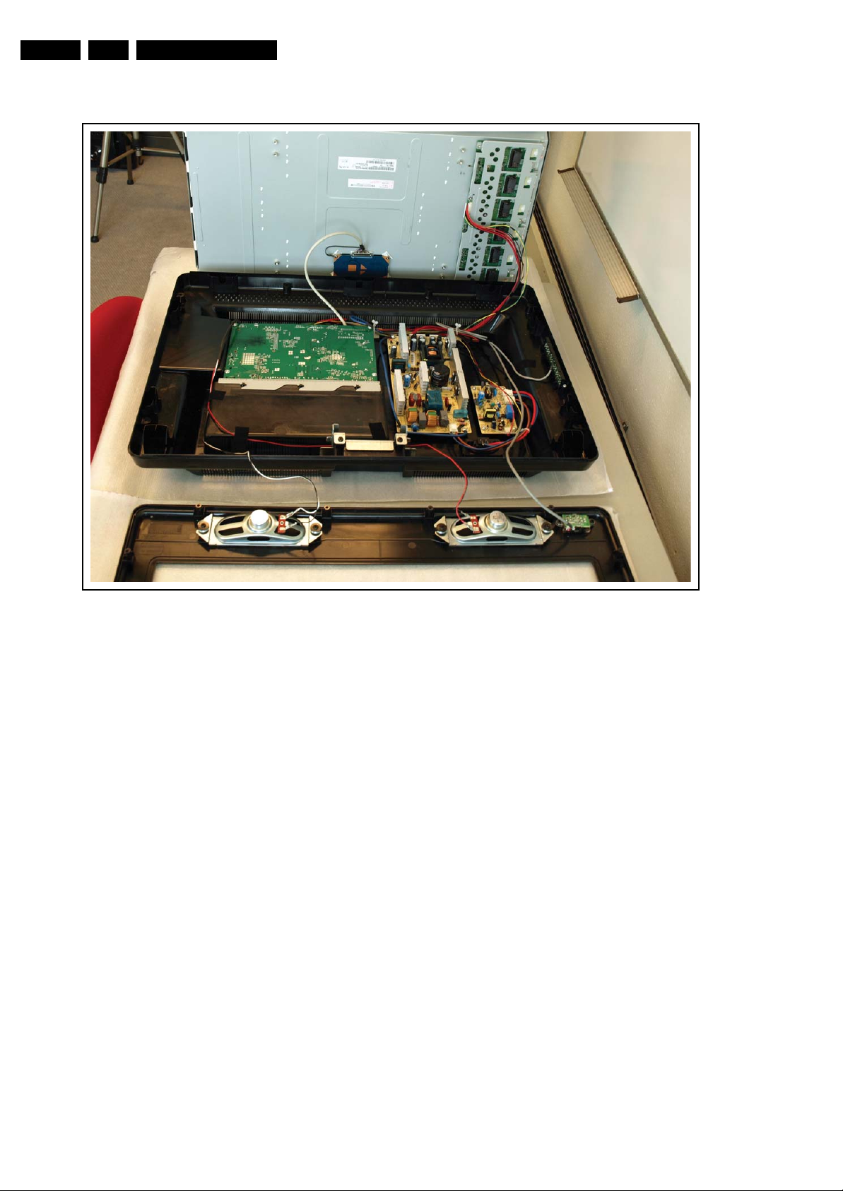
EN 8 TCS1.0L LA4.
Mechanical Instructions
Figure 4-2 Cable dressing (26" model)
I_17950_004.eps
080508
4.2 Service Positions
For easy servicing of this set, there are a few possibilities
created:
• The buffers from the packaging.
• Foam bars (created for Service).
Mechanical Instructions
EN 9TCS1.0L LA 4.
1
1
4.2.1 Foam Bars
Required for sets
1
42"
Figure 4-3 Foam bars
1
E_06532_018.eps
171106
1
Figure 4-4 Stand
4.3.2 Rear Cover
Warning: Disconnect the mains power cord before you remove
the rear cover.
1. Refer to next figures.
2. Place the TV set upside down on a table top, using the
foam bars (see section “Service Positions”).
3. Remove the screws that secure the rear cover. The screws
are located at the sides.
Be careful: Now the rear cover could be lifted but the SSB
and power supply panel(s) are mounted in the rear cover
and still connected to the LCD panel and other boards.
Those cables should be released first.
4. To release the LVDS cable lift the back cover a few
centimetres and move it downwards the set. Now unplug
the LVDS connector [2].
Caution: be careful, as this is a very fragile connector!
5. Remove the screw [3].
6. Now the rear cover can be lifted to gain access to the
speaker cables and the IR/LED panel cable. Release the
connectors [4].
1
I_17950_005.eps
080508
The foam bars (order code 3122 785 90580 for two pieces) can
be used for all types and sizes of Flat TVs. See figure “Foam
bars” for details. Sets with a display of 42” and larger, require
four foam bars [1]. Ensure that the foam bars are always
supporting the cabinet and never only the display.
Caution: Failure to follow these guidelines can seriously
damage the display!
By laying the TV face down on the (ESD protective) foam bars,
a stable situation is created to perform measurements and
alignments. By placing a mirror under the TV, you can monitor
the screen.
4.3 Assy/Panel Removal
4.3.1 Stand
1. Refer to next figure.
2. Place the TV set upside down on a table top, using the
foam bars (see section “Service Position”).
3. Remove the screws that secure the stand and remove the
stand.
2
Figure 4-5 LVDS release
3
I_17930_041.eps
240408

EN 10 TCS1.0L LA4.
Mechanical Instructions
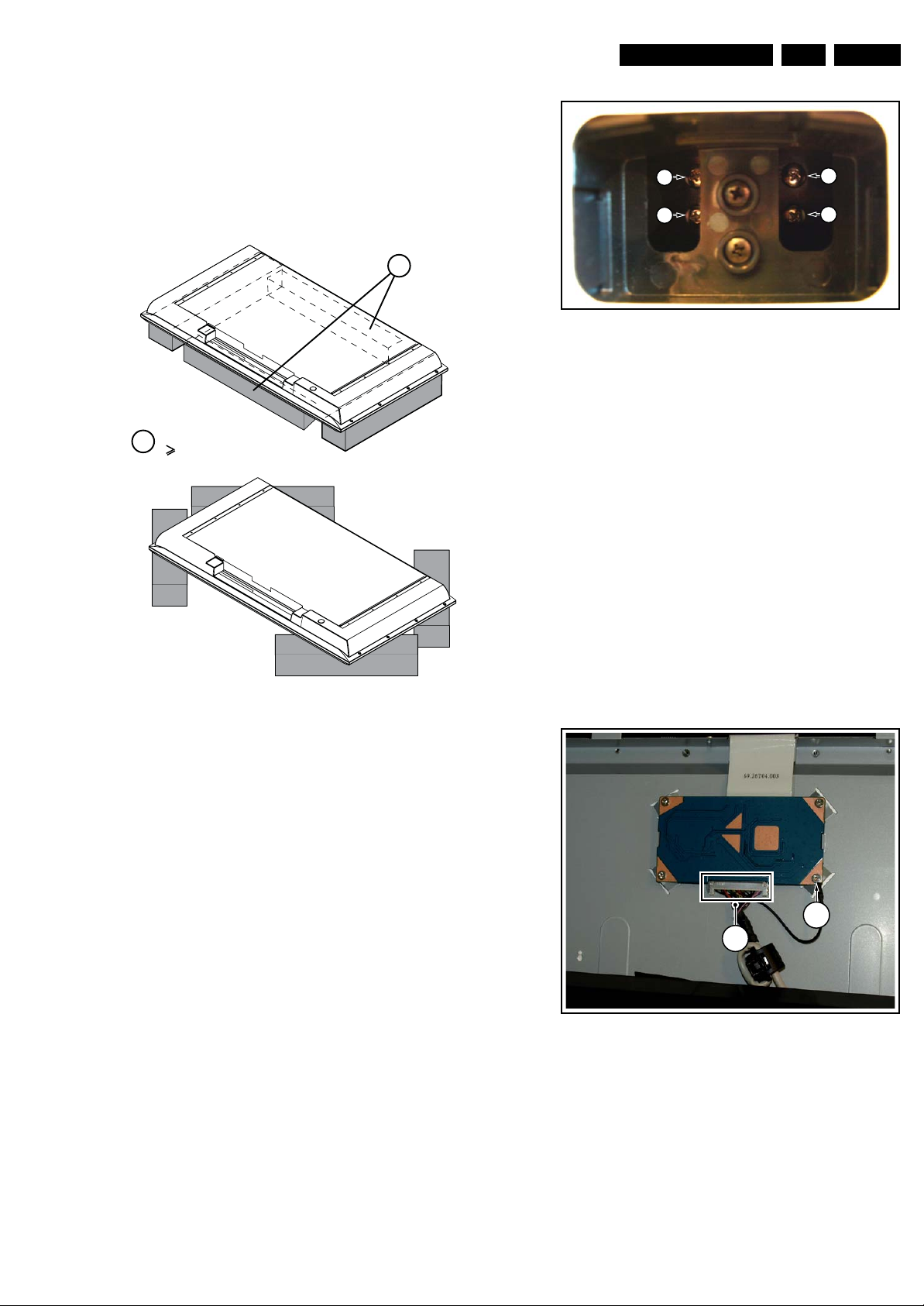
4.3.4 IR/LED Board and Speakers
1. Refer to next figure.
2. Remove the screws [1] and remove the IR/LED board.
3. Remove the screws [2] and remove the speakers.
When defective, replace the whole unit.
4
4
Figure 4-6 Speaker and IR/LED panel cable release
4.3.3 Keyboard Control Board
1. Refer to next figure.
2. Unscrew two screws[1]
3. Unplug connector [2] and remove the board.
When defective, replace the whole unit
1
2
4
I_17930_042.eps
240408
22 22
1 1
Figure 4-8 IR/LED Board and Speakers
I_17930_043.eps
240408
1
Figure 4-7 Keyboard control board
I_17930_063.eps
240408
Mechanical Instructions
EN 11TCS1.0L LA 4.
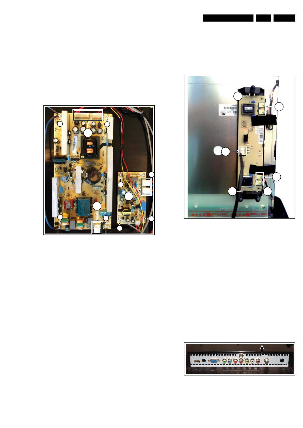
4.3.5 Power Supply Board
Due to different set executions this chassis is supplied with one
or two power supply boards and figures may differ.
Caution: it is absolutely mandatory to remount all different
screws and cables at their original position during re-assembly.
Failure to do so may result in damaging the power supply.
1. Refer to next figure.
2. Unplug all the connectors [1].
3. Remove the fixation screws [2]
4. Remove the main power supply board.
5. Unplug all the connectors [3].
6. Remove the fixation screws [4]
7. Remove the stand-by power supply board.
2
2
1
4
4.3.6 Inverter Board (19" and 22" versions)
Due to different set executions this chassis some versions are
supplied with an inverter board. Figures may differ.
1. Refer to next figure.
2. Unplug all connectors [1].
3. Release the clips [2]
4. Take out the inverter board.
2
1
1
4
2
1
2
3
1
2
2
Figure 4-9 Power Supply Unit(s)
4
4
I_17950_006.eps
080508
Figure 4-10 Inverter Board
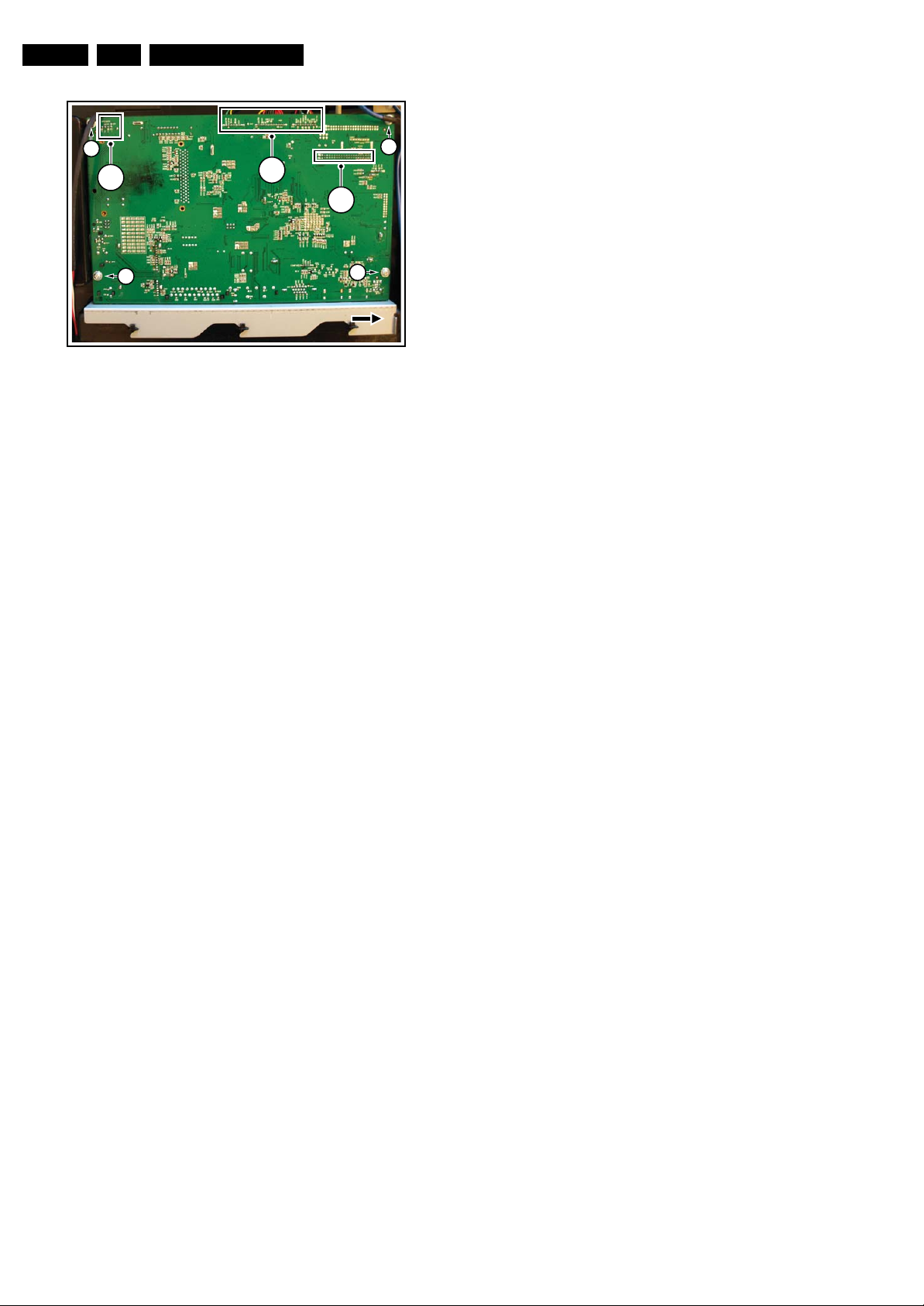
4.3.7 Small Signal Board (SSB)
Caution: it is absolutely mandatory to remount all different
screws at their original position during re-assembly. Failure to
do so may result in damaging the SSB.
Removing the SSB
1. See next figures.
2. Remove the screws [2] from the SSB.
3. On the outside of the set, lift the rear cover near the tuner
connector approximately 3 mm in the indicated direction
and keep it lifted, while
4. On the inside of the set, slide the metal plate in the
indicated direction.
5. Gently lift the board from the rear cover.
6. Now unplug the LVDS connector [3].
Caution: be careful, as this is a very fragile connector!
Unplug the rest of the cables [4].
I_17930_065.eps
240408
Figure 4-11 SSB connector plate
I_18130_002.eps
170608
EN 12 TCS1.0L LA4.
Mechanical Instructions
2
4
2
Figure 4-12 SSB
4
4.4 Set Re-assembly
To re-assemble the whole set, execute all processes in reverse
order.
Notes:
• While re-assembling, make sure that all cables are placed
and connected in their original position. See figure “Cable
dressing”.
• Pay special attention not to damage the EMC foams at the
SB shields. Make sure, that EMC foams are put correctly
on their places.
2
3
2
I_17950_008.eps
080508
Service Modes, Error Codes, and Fault Finding
5. Service Modes, Error Codes, and Fault Finding
Index of this chapter:
5.1 Test Points
5.2 Service Mode
5.3 Error Codes
5.4 Fault Finding
5.5 Service Tools
5.6 Software Upgrading
5.1 Test Points
This chassis is NOT equipped with test points in the service
printing. No test points are mentioned in the service manual.
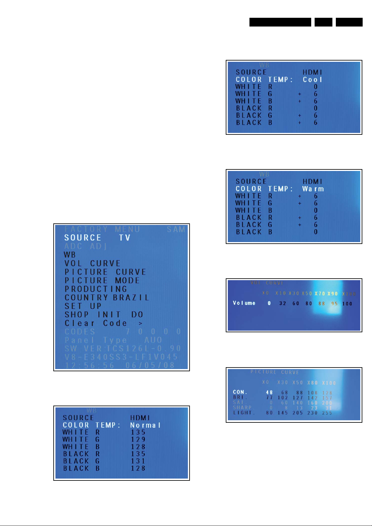
5.2 Service Mode
Figure 5-3 SAM menu, White Balance, Cool
5.2.1 Service Alignment Mode (SAM)
How to Enter
To enter SAM, use the following method:
• Press on the remote control the code “062596” directly
followed by the “INFO” key.
EN 13TCS1.0L LA 5.
I_18130_043.eps
190608
After entering SAM, the following screen is visible, the values
can be adjusted according to the requested (see Chapter 8).
I_18130_041.eps
190608
Figure 5-4 SAM menu, White Balance, Warm
Figure 5-5 SAM menu, Volume Curve
I_18130_045.eps
190608
I_18130_044.eps
190608
Figure 5-1 SAM menu
I_18130_044.eps
Figure 5-2 SAM menu, White Balance, Normal
190608
Figure 5-6 SAM menu, Picture Curve
I_18130_048.eps
190608
EN 14 TCS1.0L LA5.
Service Modes, Error Codes, and Fault Finding
I_18130_049.eps
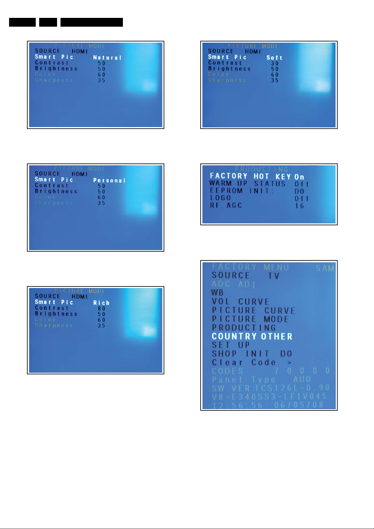
Figure 5-7 SAM menu, Picture Mode, Natural
I_18130_050.eps
Figure 5-8 SAM menu, Picture Mode, Personal
190608
190608
Figure 5-10 SAM menu, Picture Mode, Soft
Figure 5-11 SAM menu, Producting
I_18130_052.eps
190608
I_18130_053.eps
190608
Figure 5-9 SAM menu, Picture Mode, Rich
I_18130_051.eps
190608
Figure 5-12 SAM menu, Country
I_18130_054.eps
190608
Service Modes, Error Codes, and Fault Finding
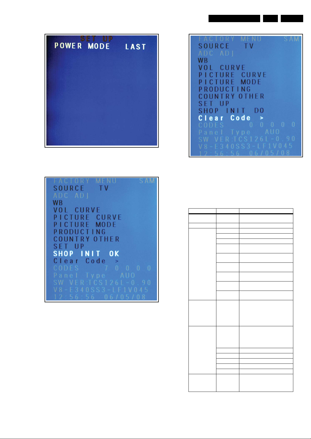
Figure 5-13 SAM menu, Setup
I_18130_055.eps
190608
EN 15TCS1.0L LA 5.
I_18130_059.eps
190608
Figure 5-14 SAM menu, Shop Init Do
I_18130_058.eps
190608
Figure 5-15 SAM menu, Clear Code >
How to Exit
Press “MENU” on the RC-transmitter.
Factory Mode Descriptions
Item Sub-Item Description
SOURCE Shift among sourcing via pressing
ADC ADJ Only available in HDTV or PC mode
WB White Balance Calibration setting
SOURCE Shift among sources
COLOR TEMP Normal, Warm, Cool
WHITE R R Gain, adjust manually or
WHITE G G Gain, adjust manually or
WHITE B B Gain, adjust manually or
BLACK R R Shift, adjust manually or
BLACK G G Shift, adjust manually or
BLACK B B Shift, adjust manually or
VOL CURVE Volume Curve adjustment;
PICTURE C URVE Anal og Picture Curve adjustment; X0,
CON Contrast Curve
BRI Brightness Curve
SAT Saturation Curve
SHARP Sharpness Curve
LIGHT Back light Curve
PICTURE MODE Picture modes analog value can be
Left & Right key
automatically
automatically
automatically
automatically
automatically
automatically
X0, X10, X30, X50, X70, X90, X100
on for the user
menu volume value of the 0, 10, 30,
50, 70, 90, 100.
Only to adjust during production.
X30, X50, X80, X100 on for the user
menu picture value of the 0, 30, 50,
80, 100.
Only to adjust during production.
adjusted in this page,
including SOFT, NATURAL,
BRIGHTE and PERSONAL
EN 16 TCS1.0L LA5.
Service Modes, Error Codes, and Fault Finding
Item Sub-Item Description
PRODUCTING FACTURY
COUNTRY Select the correct country before
SET UP POWER
SHOP INIT DO By selecting this, the outgoing factory
CLEAR CODE > Clears the Error codes
CODES Shows the last 5 error codes
PANEL TYPE Shows the panel type (display only)
SW VER Shows the software version
V8-... Shows the BOM number
COMPILE TIME Shows the time the software was
HOT KEY
WARM UP
STATUS
EEPROM INIT EEPROM initialization:
LOGO Always leave this setting to the value
RF AGC RF Automatic Gain Control default at
MODE LAST
POWER
MODE STB
POWER
MODE ON
Short-cut key to enter factory mode
setting: GO BACK is the short-cut key
if it is “ON”. Do remember to turn
this “OFF” when the set is returned
to the customer.
Aging Mode setting: “ON” means
snow picture showing instead of blue
background if there is no signal input.
Do remember to turn this “OFF”
when the set is returned to the
customer.
1. When the first time to turn on the
set, please enter this menu and
initialize it.
2. Press Left/Right key and waiting for
about 5 seconds until “OK” displayed,
which means the set finishes the
initialization.
3. Switch off AC power.
4. Power on the set again, the
EEPROM will be initialized.
“OFF”.
16
doing a SHOP INIT, because it puts
the set in virgin mode.
This selects the last power on
sequence used.
This will put the set in Stand-by
whenever the power key is used to
turn it on. The user now has to t urn the
set on with the remote control.
This will turn on the set whenever the
power key is used to turn it on.
initialization is selected. Always
perform this at the end of a repair.
compiled.
Virgin Settings
First the country should be set according to the following table:
Table 5-1 Country setting
CTN suffix Country
/55 Other
/77 Argenti na
/78 Brazil
/85 Mexico
Secondly select “SHOP INIT” from the SAM menu. Wait until
finished and then turn “Off” the set. Now the set is put back to
virgin settings according to the following table.
Table 5-2 Virgin settings
Setting /55 /77 /78 /85
PQ Smart Mode Rich Rich Rich Rich
AQ Smart Mode Movie Movie Movie Movie
Sleep Off Off Off Off
Time 00:00 00:00 00:00 00:00
Start time --:-- --:-- --:-- --:--
Stop time --:-- --:-- --:-- --:--
Channel 2 2 2 2
Child lock Off Off Off Off
Parental lock Off Off Off Off
Closed caption Off Off Off Off
RF Channel 2 9 4 2
Volume 30 30 30 30
Setting /55 /77 /78 /85
Screen ratio 16:9 16:9 16:9 16:9
OSD language Spanish Spanish Portuguese Spanish
5.2.2 Customer Service Mode (CSM)
Purpose
When a customer is having problems with his TV-set, he can
call his dealer or the Customer Help desk. The service
technician can then ask the customer to activate the CSM, in
order to identify the status of the set. Now, the service
technician can judge the severity of the complaint. In many
cases, he can advise the customer how to solve the problem,
or he can decide if it is necessary to visit the customer. The
CSM is a read only mode; therefore, modifications in this mode
are not possible.
How to Activate CSM
Key in the code “123654” via the standard RC transmitter.
Contents of CSM
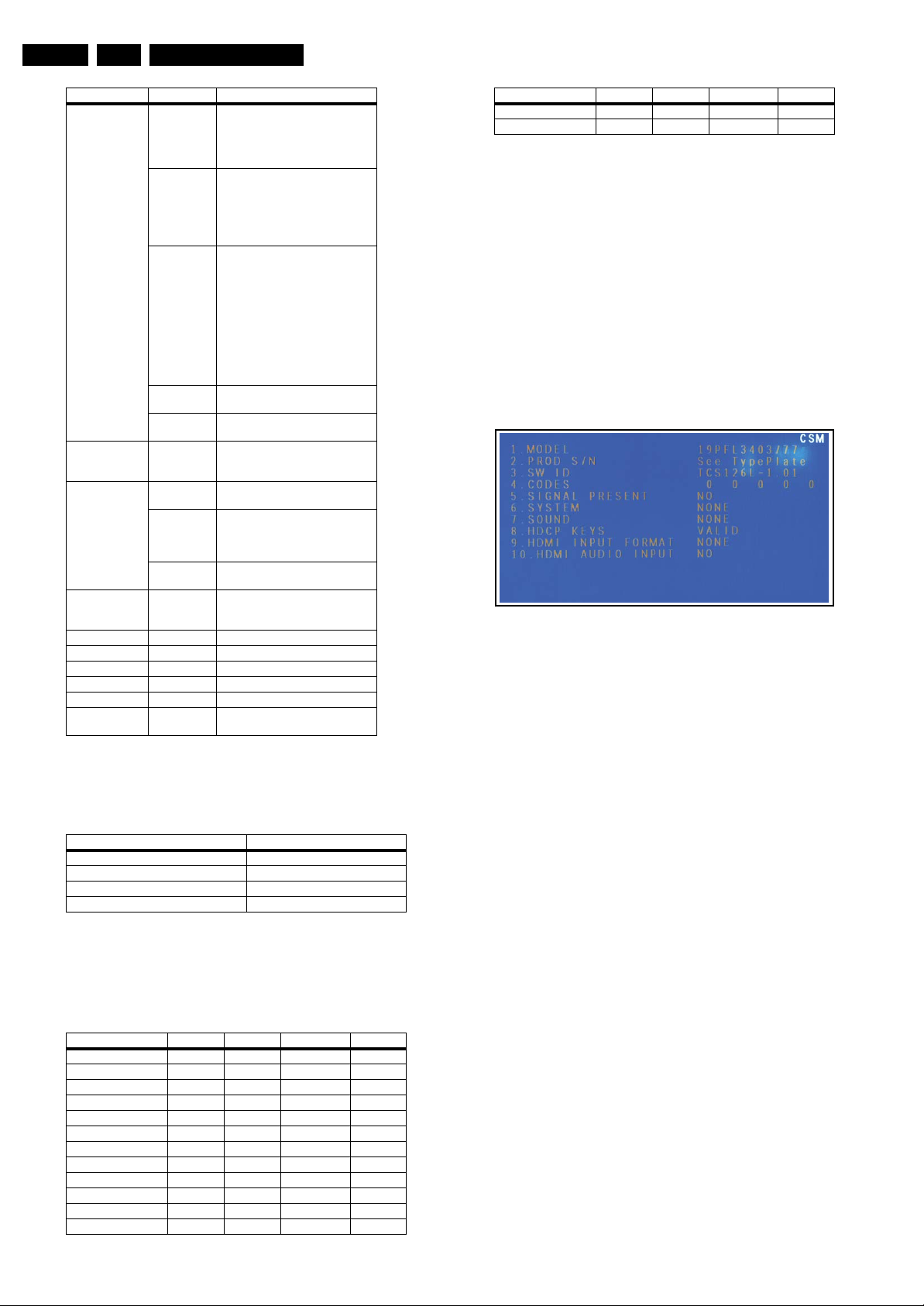
Figure 5-16 CSM Menu
Menu Explanation
1. MODEL Type number and region code.
2. PROD S/N Production code will have 14 characters + 2
reserved (total 16 characters).
3. SW ID Software cluster and version is displayed (TC =
TCL, 1 = Chassis Number, 26 = Screen size, L = Latam,
0.90 = software version).
4. CODES Error buffer contents.
5. SIGNAL PRESENT Presence of RF signal.
6. SYSTEM Color system.
7. SOUND Sound system (Mono/Stereo/SAP).
8. HDCP KEYS Shows Valid or invalid HDCP key when
HDMI connected. Else blank.
9. HDMI INPUT FORMAT Shows the HDMI input format.
10. HDMI AUDIO INPUT HDMI audio input HDMI audio stream
detection. YES = Audio stream detected. NO = No Audio
(for example when DVI format is used)
How to Exit
Press “MENU” on the RC-transmitter.
5.2.3 Blinking LED Procedure
The software is capable of identifying different kinds of errors.
Because it is possible that more than one error can occur over
time, an error buffer is available which is capable of storing the
last five errors that occurred. This is useful if the OSD is not
working properly.
Errors can also be displayed by the blinking LED procedure.
The method is to repeatedly let the front LED pulse with as
many pulses as the error code number, followed by a period of
1.5 seconds in which the LED is “off”. Then this sequence is
repeated.
I_18130_060.eps
190608

Service Modes, Error Codes, and Fault Finding
Any RC command terminates the sequence. Error code LED
blinking is in white color.
Example: the contents of the error buffer is
“013 007 000 000 000”.
After entering SDM, the following occurs:
• 1 long blink of 5 seconds to start the sequence
• 1 medium blink of 3 seconds and then 3 short blinks
followed by a pause of 1.5 seconds
• 7 short blinks followed by a pause of 1.5 seconds
• 1 long blink of 1.5 seconds to finish the sequence.
The sequence starts again with 12 short blinks.
5.3 Error Codes
The error code buffer contains all errors detected since the last
time the buffer was erased. The buffer is written from left to
right. When an error occurs that is not yet in the error code
buffer, it is displayed at the left side and all other errors shift one
position to the right.
5.4 Fault Finding
Basically there are six kind of errors:
Code Description Detection method Type
0 no error - -
1 reserved - -
2 5V failure
protection
3 μP Control I
4 General I
bus Error
5 reserved - -
6System
EEPROM
7 Tuner I
8 HDCP
EEPROM
Power down Protection +
2
C-bus Error log +
2
C
I2C-bus Protection +
2
C-bus Protection +
I
2
C-bus Error log +
2
C-bus Error log +
I
blinking
blinking
blinking
blinking
blinking
blinking
EN 17TCS1.0L LA 5.
No Picture, no sound, no Back light
For P22 ,Pin 1~4 is
+12V_PW& Pin7~9
of is +5VSTB
OK?
YES
Fuse F3(3A) OK?
YES
Check circuit of
+3.3V,+1.8V(U5,U
6,U7) OK?
YES
Check Q17(Pin5-
8):+12V OK?
YES
Check DC-DC
circuit(U1,U2)
NO
Check PSU
NO
Replace F3
NO
Replace the bad
components
NO
Check Q26 circuit
& Replace the bad
components
Figure 5-17 No Picture, No sound, no Back light (19" sets)
I_18130_066.eps
180608

EN 18 TCS1.0L LA5.
˄
Service Modes, Error Codes, and Fault Finding
Picture OK, No sound
Check the voltage of
Pin 3,13 of U19,is it 12v?
Yes
Check Mute Pin6 of U19,is it 12V?
Yes
Check the wave of
pin74,75 of U8,is it
OK?
No
TV source
Yes
Check SIF circuit
Pin 7(SIFOUT) of
Tuner TU1
Yes
No
No
R & L speaker
Check wave of
Audio input Pin
U8 pin61~69. OK?
Figure 5-18 Picture OK, No sound (19" sets)
Check
Replace
U8
Check Q17
NO
Yes
Check B of Q22 is
Low OK?
Check
Q22
No
Check
the AV input
circuit
Yes
No
Check the AMP-
MUTE circuit
I_18130_068.eps
180608
No Picture, Back light & Sound OK
Check the
output voltage
of U3
12V˅. is
it OK?
Yes
Check LVDS
signal waveform
of P10 is OK?
No
Figure 5-19 No Picture, Back light & Sound OK (19" and 26" sets)
Is RP2-RP7 ok?
No
Yes
Yes
Check the Circuit of
12V_PANEL&
PANEL_ON/OFF
check the LVDS
cable
Replace U8
I_18130_004.eps
180608
 Loading...