

Page 1
Colour Television Chassis
TC 4.1U
AA
Contents Page
1 Technical Specifications, Connections 2
2 Safety and Maintenace Instructions, Warnings
and Notes 4
3 Directions for Use 6
4 Mechanical Instructions 28
5 Service Modes, Error Codes and Fault Finding 32
6 Block Diagram, Waveforms, Wiring Diagram 45
7 Electrical Diagram and Print Layouts 46
8 Alignments
9 Circuit-, IC Descriptions and List
of Abbreviations 65
10 Spare Parts List 79
55
Page 2
EN 2 TC4.1U AA1.
Technical Specifications, Connections
1. Technical Specifications, Connections
Note: Described specifications are valid for the whole product range.
1.1 Technical Specifications
1.1.1 Reception
Tuning system : PLL
Colour system : NTSC M
Sound system : BTSC
A/V connections : PAL 4.43
:NTSC
3.58&NTSC4.43
Channel selections : 181 channels
IF frequency : 45.75MHz
Aerial input : 75Ω,Coaxial
1.1.2 Miscellaneous
Audio output(RMS) : 24W
Mains voltage : 120V(±10%)
Mains frequency : 60Hz(±5%)
Ambient temperature : +5 to +45 deg. C
Maximum humidity : 90% R.H.
Power consumption : 98W
Standby Power consumption : <1W
1.2 Connections
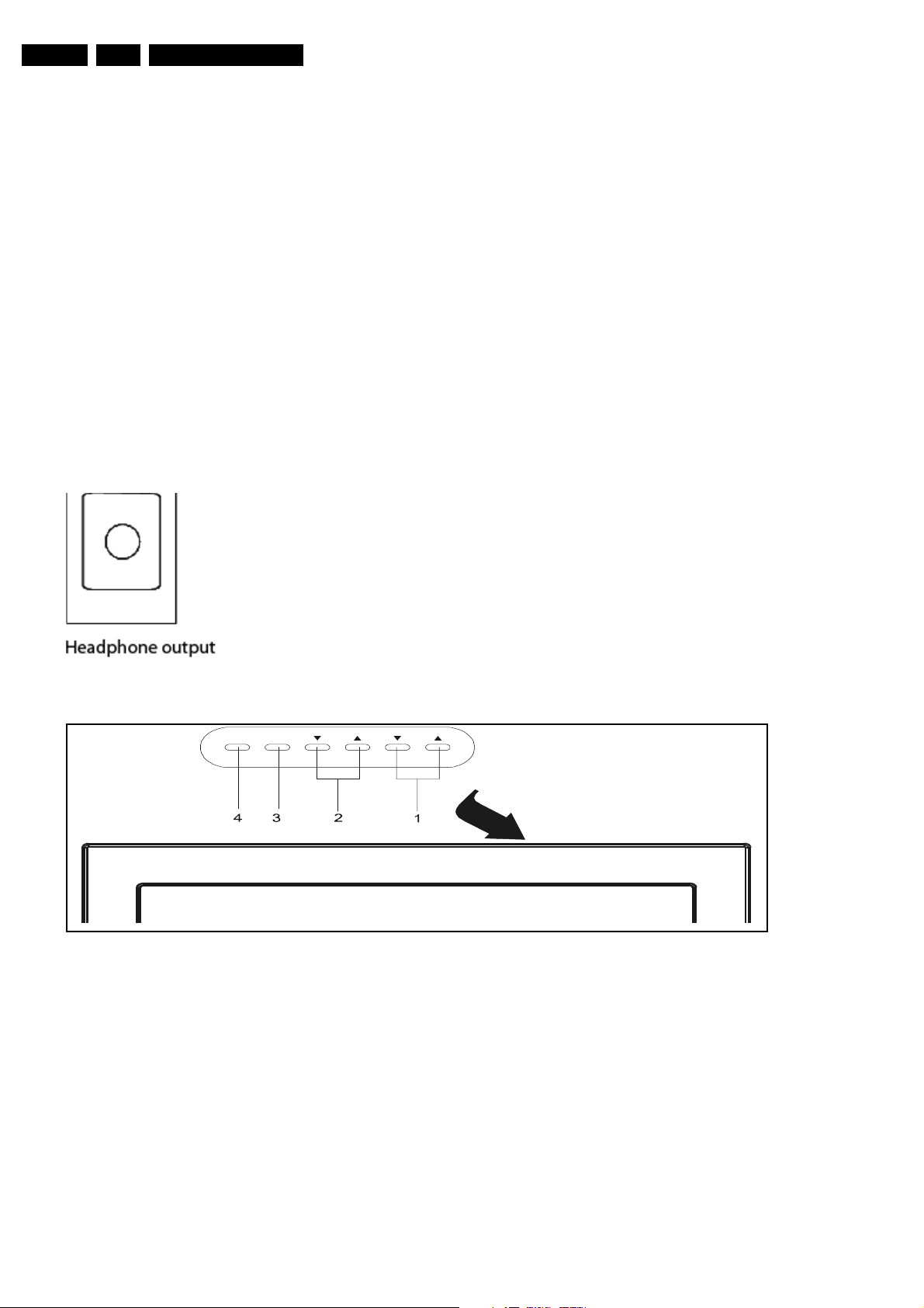
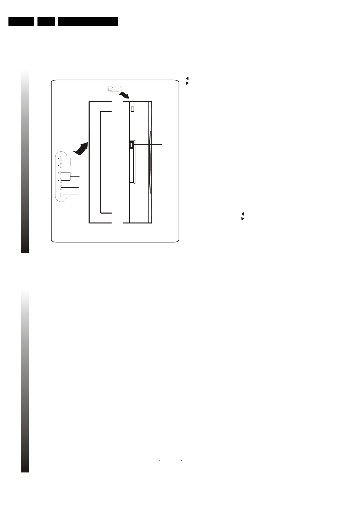
1.2.1 Side connections, Top (or Front) Control
SIDE I/O
Figure 1-1
TOP CONTROL
TV/AV/DVD
1. Chanel up/down buttons
2. Volume/picture control buttons
3. Menu button
4. TV/AV/DVD button
MENU VOL. CH.
EN ER PLAY/PAUSE
Figure 1-2
Page 3
Technical Specifications, Connections
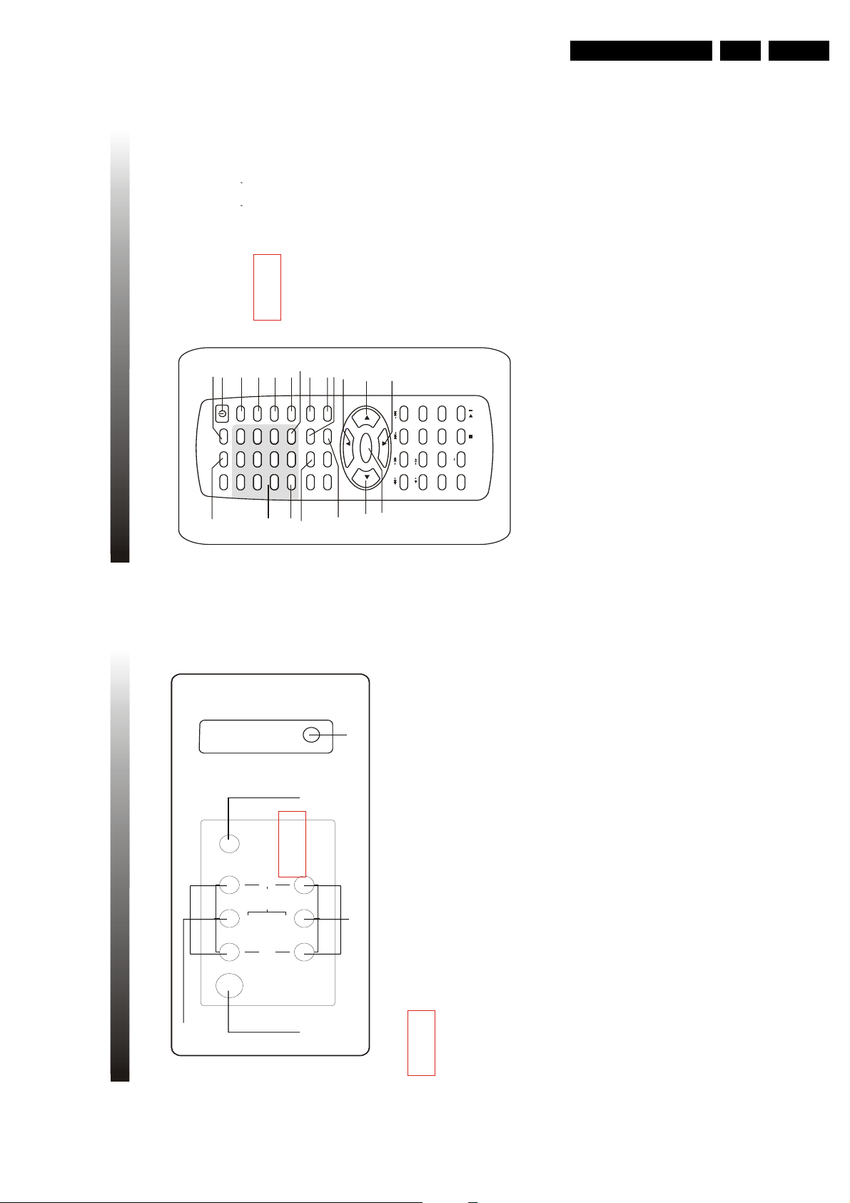
OWER
COAXIAL
DVD DIGITAL
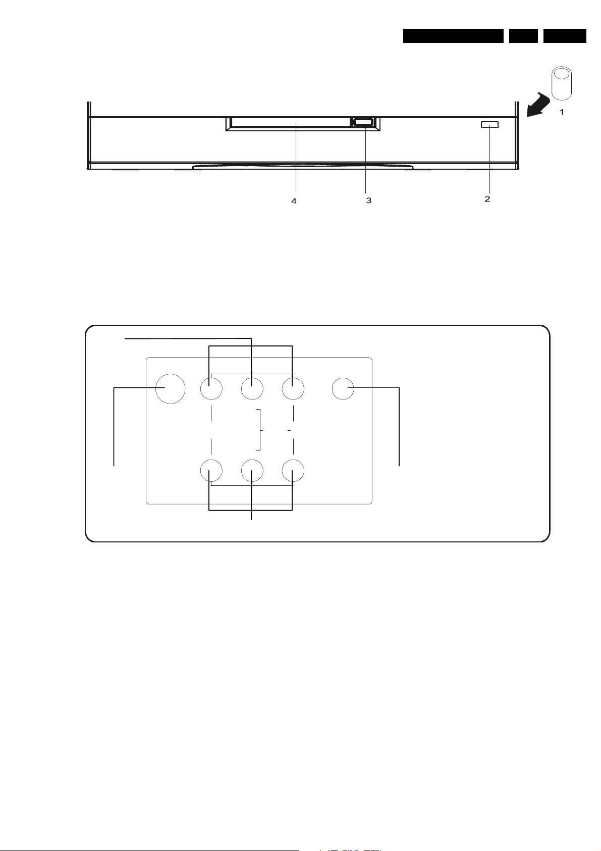
FRONT CONTROL
Figure 1-3
1. Power button
2. Standby indicator
3. Open button
4. Open door
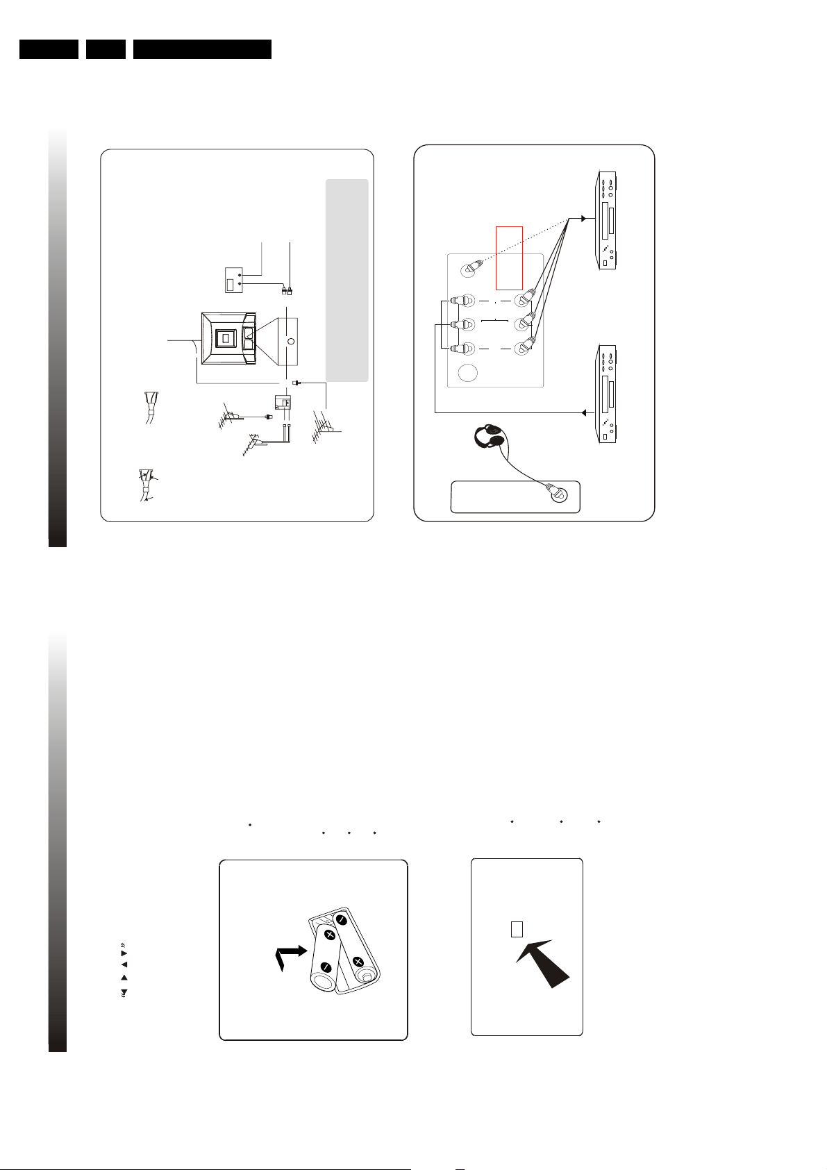
1.2.2 Rear Connections
EN 3TC4.1U AA 1.
2
AV INPUT
75 OHM
ANTENNA
INPUT
VIDEO AUDIO
L
(MONO)
L
R
1
AV OUTPUT
4
1. 75 OHM antenna input
2. Audio/Video in(AV input)
3. DVD digital video output/coaxial
4. Audio/Video output(Monitor output)
Audio/video in
OUTPUT
3
Figure 1-4
1. Video CVBS (1Vpp/75Ω)
2. Audio L (0.5 Vrms/10kΩ)
3. Audio R (0.5 Vrms/10kΩ)
4. headphone 3.5mm(8 - 600Ω/4Mw)
Page 4

EN 4 TC4.1U AA2.
Safety & Maintenance Instructions, Warnings, and Notes
2. Safety & Maintenance Instructions, Warnings, and Notes
2.1 Safety Instructions For Repairs
2.1.1 General Safety
Safety regulations require that during a repair
• Due to the ‘hot’ parts of this chassis, the set must be
connected to the AC power via an isolation transformer.
• Safety components, indicated by the symbol , should be
replaced by components identical to the original ones.
• When replacing the CRT, safety goggles must be worn.
Safety regulations require that after a repair, the set must be
returned in its original condition. Pay particular attention to the
following points:
• General repair instruction: as a strict precaution, We advise
you to re-solder the solder connections through which the
horizontal deflection current is flowing, in particular:
– all pins of the line output transformer(LOT)
– fly-back capacitor(s)
– S-correction capacitor(s)
– line output transistor
– pins of the connector with wires tothe deflection
coil
– other components through which the deflection current
flows.
Note: This re-soldering is advised to prevent bad connections
due to metal fatigue in solder connections and is therefore only
necessary for television sets more than two years old.
• Route the wire trees and EHT cable correctly and secure
them with the mounted cable clamps.
• Check the insulation of the AC power cord for external
damage.
• Check the strain relief of the AC power cord for for proper
function, to prevent the cord from touching the CRT, hot
components,or heat sink.
• Check the electrical DC resistance between the AC plug
and the secondary side (only for sets that have an isolated
power supply). Do this as follows:
1. Unplug the AC power cord and connect a wire between
the two pins of the AC plug.
2. Turn on the main power switch (keep the AC power
cord unplugged)
3. Measure the resistance value between the pins of the
AC plug and the metal shielding of the tuner or the
aerial connection of the set. The reading should be
between 4 M and 8 M.
4. Switch the TV OFF and remove the wire between two
pins of the AC plug.
• Check the cabinet for defects, to prevent the the possibility
of the customer touching any internal parts.
Figure 2-1 Class 1 Laser Product
Note: Use of controls or adjustments or performance of
procedure other than those specified herein, may result in
hazardous radiation exposure. Avoid direct exposure to beam.
2. 1.3 Sh ock , F ire Hazar d Serv ice Te st
Caution: After servicing this appliance and prior to returning to
customer, measure the resistance between either primary AC
cord connector pins (with unit NOT connected to AC mains and
its Power switch ON), and the face or Front panel of the
product and controls and chassis bottom.
Any resistance measurement less than 1 Megohms should
cause unit to be repaired or corrected before AC power is
applied, and verified before return to user/customer. Ref. UL
Standard NO. 1492
Note on safety:
Symbol : Fire or electrical shock hazard. Only original parts
should be used to replace any part with symbol (other than
original type), may increase risk or fire or electrical shock
hazard.
2. 2 2. 2 Ma i n te n a nc e I n st r u cti o n s
It is recommended to have a maintenance inspection carried
out by qualified service personnel. The interval depends on the
usage conditions:
• When the set is used under normal circumstances, for
example in a living room, the recommended interval is
three to five years.
• When the set is used in an environment with higher dust,
grease or moisture levels, for example in a kitchen, the
recommended interval is one year.
• The maintenance inspection includes the following actions:
1. Perform the 'general repair instruction' noted above.
2. Clean the power supply and deflection circuitry on the
chassis.
3. Clean the picture tube panel and the neck of the picture
Tube.
2.3 Warnings
2.1.2 2.1.2 Laser Safety
This unit employs a laser .Only qualified service personel
remove the cover, or attempt to service this device (duo to
possible eye injury).
Laser Device Unit
Type : semiconductor laser
GaA/As
Wavelength : 650 nm (DVD)
: 780 nm (VCD/CD)
Output Power : 7 mW (DVD)
: 10 mW (VCD/DVD)
Beam divergence : 60 degree
2.3.1 2.3.1 General
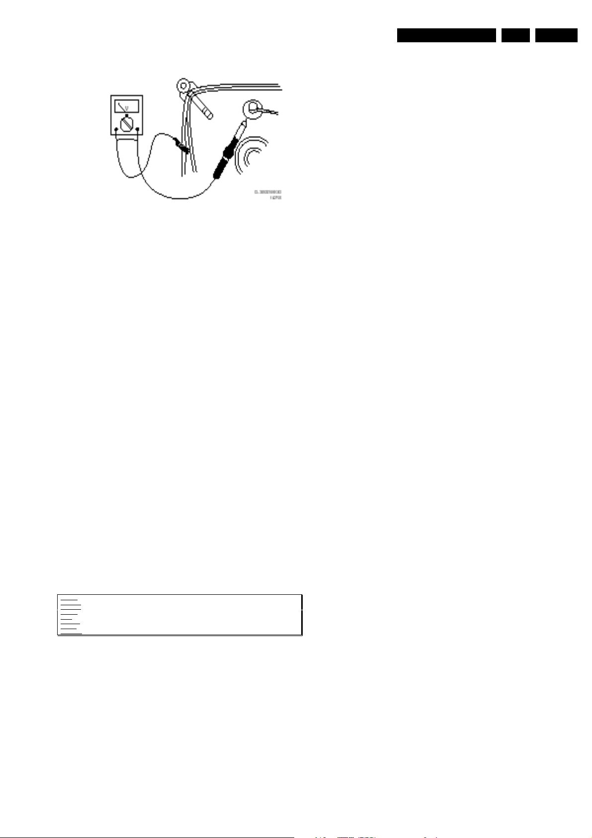
• In order to prevent damage to ICs and transistors, avoid all
high voltage flashovers. In order to prevent damage to the
picture tube, use the method shown in Fig. 2-1, to dischage
the picture tube. Use a high voltage probe and a multimeter (position VDC). Discharge until the meter reading is
0 V (after approx. 30 s).
Page 5
Safety & Maintenance Instructions, Warnings, and Notes
Figure 2-2
• All ICs and many other semiconductors are susceptible to
electrostatic discharges (ESD). Careless handling during
repair can reduce life drastically. When repairing, make
sure that you are connected with the same potential as the
mass of the set by a wristband with resistance. Keep
components and tools also at this potential. Available ESD
protection equipment:
– Complete kit ESD3 (small tablemat, wristband,
connection box, extension cable, and ground cable)
4822 310 10671.
– Wristband tester 4822 344 13999.
• Together with the deflection unit and any multi-pole unit.
flat square picture tubes form an integrated unit. The
deflection and the multi-pole units are set optimally at the
factory. Adjustment of this unit during repair is therefore not
recommended.
• Be careful during measurements in the high voltage
sect i o n sec t i on an d o n the p i c ture t u be.
• Never replace modules or other components while the unit
is switched ON.
• When you align the set, use plastic rather than metal tools.
This will prevent any short circuits and the danger of a
circuit becoming unstable.
EN 5TC4.1U AA 2.
• Where necessary, measure the waveforms and voltages
with ( ) and without ( ) aerial signal. Measure the
voltages in the power supply section both in normal
operation ( ) and in standby ( ). These values are
indicated by means of the appropriate symbols.
• The picture tube panel has printed spark gaps. Each spark
gap is connected between an electrode of the picture tube
and the Aquadag coating.
• The semiconductors indicated in the circuit diagram and in
the parts lists are completely interchangeable per position
with the semiconductors in the unit, irrespective of the type
indication on these semiconductors.
2.3.2 Laser
• The use of optical instruments with this product, will
increase eye hazard.
• Only qualified service personnel may remove the cover or
attempt to service this device, due to possible eye injury.
• Repair handling should take place as much as possible
with a disc loaded inside the player.
• Text below is placed inside the unit, on the laser cover
shield.
CAUTION VISIBLE AND INVISIBLE LASER RADIATION WHEN OPEN AVOID EXPOSURE TO BEAM
ADVARSEL SYNLIG OG USYNLIG LASERSTRÅLING VED ÅBNING UNDGÅ UDSÆTTELSE FOR STRÅLING
ADVARSEL SYNLIG OG USYNLIG LASERSTRÅLING NÅR DEKSEL ÅPNES UNNGÅ EKSPONERING FOR STRÅLEN
VARNING SYNLIG OCH OSYNLIG LASERSTRÅLNING NÄR DENNA DEL ÄR ÖPPNAD BETRAKTA EJ STRÅLEN
VARO! AVATTAESSA OLET ALTTIINA NÄKYVÄLLE JA NÄKYMÄTTÖMÄLLE LASER SÄTEILYLLE ÄLÄ KATSO SÄTEESEEN
VORSICHT SICHTBARE UND UNSICHTBARE LASERSTRAHLUNG WENN ABDECKUNG GEÖFFNET NICHT DEM STRAHL AUSSETSEN
DANGER VISIBLE AND INVISIBLE LASER RADIATION WHEN OPEN AVOID DIRECT EXPOSURE TO BEAM
ATTENTION RAYONNE MENT LASER VISIBLE ET INVISIBLE EN CAS D'OUVERTURE EXPOSITION DANGEREUSE AU FAISCEAU
!
Figure 2-3 Warning text
2.4 Notes
• Measure the voltages and waveforms with regard to the
chassis (= tuner) ground (), or hot ground (),depending
on the area of circuitry being tested.
• The voltages and waveforms shown in the diagrams are
indicative. Measure them in the Service Default Mode (see
chapter 5) with a color bar signal and stereo sound
(L:3KHz, R: 1KHz unless stated otherwise) and picture
carrier at 475.25MHz (PAL) or 61.25MHz (NTSC, channel
3).
Page 6
EN 6 TC4.1U AA3.
1. POWER BUTTON
To turn ON/OFF the TV set
3. OPEN BUTTON
To open or close the open door of DVD
2. STANDBY INDICATOR
Lights when the TV is in the working mode
and goes out when it is in the standby mode
1.2.1 FRONT PANEL
1.2 DESCRIPTION OF CONTROL KEYS & CONNECTOR
7.
MENU BUTTON
To display the main menu on the screen
To decrease/increase the sound volume and
picture settings level
6. VOLUME/PICTURE CONTROL (/)
BUTTONS
8. TV/AV/DVD BUTTON
To switch between TV program AV input and
DVD sources
4. DVD OPEN DOOR
1
2
3
TV/AV/DVD
MENU
VOL
CH
EN ER PLAY P USE
OWER
4
5678
PLAY/PAUSE or ENTER as the silkprint below
shows works respectively only when the set is
in DVD state Please refer their corresponding
function introductions to the DVD section
5. CHANNEL ( / ) BUTTONS
Select program number cyclically
To turn on the TV when it is in standby mode
To select the item in sub-menus
7
1. INTRODUCTION
3. Directions For Use
Directions For Use
ncreases shadow detail without compromising overall picture contrast
Dynamically boosts the black level in the dark areas of the picture according to picture content
T NTED BR GHT BLACK P CTURE TUBE
1.1 FEATURES
1. INTRODUCTION
4 P CTURE SETT NGS
The picture this television produces can be personalized to produce the optimum display
SLEEP T MER
3 LANGUAGE OSD
This television can display the menu in three languages English French and Spanish
quality
This television can be fully operated and programmed using the supplied remote control
V-CH P
CLOSED CAPT ON DECODER
Allows parents to restrict viewing of certain channels containing content they deem inappropriate
Lets the user watch television for a preset amount of time before the unit goes into standby
mode This television can be programmed up to 120 minutes (10 minutes intervals)
FULL FUNCT ON REMOTE CONTROL
local listings for program broadcasts that have been closed captioned (more on pg 26)
This television is equipped with a Closed Caption Decoder that enables the set to print the
audio portion of a television program on the screen similar to subtitles Please check your
AUTO OFF FUNCT ON
- f the TV set is turned on from ON Timer function the TV set will turn off automatically after
15 minutes without any operation on the TV set
- The TV set will turn off automatically after 4 hours without any operation on the TV set
MPX STEREO/SAP RECEPT ON
This television is designed to receive stereo and the Second Audio Program (SAP) broadcasts
where available
6
Page 7
Directions For Use
1.3 OPERATION OF REMOTE CONTROL
1.3.1DESCRIPTION OF REMOTE CONTROL KEYS
5. CLOCK BUTTON
1. STANDBY BUTTON
When the main power is on to turn the TV set on
or off
INTRODUCTION OF KEY FUNCTION
This TV features with a full-function remote handset
For a more compact remote unit design some of the
keys are multiple with more than one function The
following text describes the function of numbered keys as
dictated above Functions of keys related to DVD operation
are introduced in DVD section later
10.
DISPLAY
To display the current program number
and function status
Press the button once agin to display
9. FAV.
13.MENU
Press to access the main menu(P CTURE
SOUND FEATURE T MER and
PRESET) or go back to the previous
screen within on the screen menu
3. MUTE BUTTON
To temporarily turn off the sound and to
restore it by pressing it again
2. TV/AV/DVD BUTTON
To switch between the TV program AV
input and DVD sources
4.
SLEEP BUTTON
Set the sleep timer from 120 to 10
minutes by pressing the SLEEP button
repeatedly To display the remaining
time press the SLEEP button once To
cancel the sleep timer press the
SLEEP button until OFF appears
RECALL BUTTON
Press to return to the previously
viewed channel
12.
8. (0-9) DIGIT KEYS
To select program number directly
VOLUME UP/DOWN BUTTON
To decrease or increase the sound
volume and picture setting level
11.
PO ER
SLEEP
VOL+
PCTURE/DEL
SEFFECT
VOL-
MTS
MENU
TVAV D
DSP AY
R/L
SKP
SEARCH
MODE
SUBTTLE ZOOM
STOP PLAY PAUSE
/
9
6
3
MUTE
RECALL
OPENCLOSE
TTLE
MENUPCB SETUP
SCAN
REPEAT
LANGUAGE ANGLE
REPEAT
A B
ENTER
21
AV.
8
7
5
4
0
CH+
SLOW
1
2
3
5
6
7
8
9
10
12
11
13
15
17
4
11
15
14
16
Pressing the MENU button in the first
screen of the main menu at any time will
exit the menu
17
To browse the preset favorite channels
This button will not function if you have
not set any favorite program
PICTURE/DEL. BUTTON
Cyclically selects the 5 picture settings
Movies-Sports-Week Signal-Multimedia
-Personal
7.
n favourite list setting to delete or restore
a favourite channel
To jump to clock setting in TV status
SOUND EFFECT BUTTON
6.
To switch between the 4 sound effect settings
circularly Voice Music Theatre Personal
CLOCK
DVD10+
CH-
1. INTRODUCTION
9
EN 7TC4.1U AA 3.
DVD DIGITAL
1.2.2 REAR & SIDE TERMINAL
1. INTRODUCTION
2
AV NPUT
HEADPHONE
3
OUTPUT
COAXIAL
R
L
(MONO)
INPUT
75 OHM
ANTENNA
L
VIDEO AUDIO
1
5
AV OUTPUT
1. 75 OHM ANTENNA INPUT
2 AUDIO/VIDEO IN (AV INPUT)43. DVD DIGITAL OUTPUT/ COAXIAL
5. HEADPHONE OUTPUT
4. AUDIO/VIDEO OUT (MONITOR OUTPUT)
8
Page 8
EN 8 TC4.1U AA3.
Before plugging the UHF/VHF Rod Antenna into the
ANT(enna). In jack, check that the pin is not bent. If
it is bent, straighten the pin as i lustrated, then plug
the pin into the ANT(enna). In jack.
*
Some cab e TV sys ems use scrambed
signa s and require a specia converter
to receive these channe s. Consut your
oca cabe company.
FCC WARNING -Ths equ pment may generate or use rad o
frequency energy. Changes or modf cat ons to th s equ pment
may cause harmfu nterference un ess the mod f cat ons are
express y approved n the nstruct on Manua . The user cou d
ose the author y to operate th s equpment f an unauthor zed
change or mod fcat on s made.
Cabe
Pug
Bent pn
(Needs to be straightened)
( straight pin)
UHF
Antenna
(Not supp ed)
VHF
Antenna
(Not supp ed)
OROR
OUT
N
ANT.IN
From Cable System
or Satellite Antenna
75-ohm
Coaxial Cable
From Cable System
UHF/VHF Rod
Antenna
(Supp ed)
CATV Box
or Sate e Box
(Not supp ed)
*
Note to CATV system installer:
This reminder is provided to call the CATV system instaler's attention to Article 820-40
of the NEC that provides guidelines for proper grounding and, in particular, specifies that
the cable ground sha l be connected to the grounding system of the bulding as close to
the point of cable entry as practical.
VHF/UHF
Combnat on An enna
(Not supp ed)
VHF UHF
Combner
(Not supp ed)
75-ohm
Coaxial Cable
2.1 CABLE/ANTENNA CONNECTIONS
75 OHM
ANTENNA
INPUT
VIDEO AUD O
COAX
DVD D GITAL
OUTPUT
R
AV UT
V OUTPUT
L
L
MONO
2.2 EXTERNAL CONNECTIONS
A VCR or other video component can
be connected to this unit for dubbing.
A VCR, DVD player, video game
system or other audio/video component
can be connected here.
AV N
MONITOR OUT
HEADPHONE
2. CONNECTIONS
11
Directions For Use
CHANNEL UP/DOWN BUTTON
To cyclically select the program number
ENTER BUTTON
Within the on-screen menu press to enter
some special function such as Calendar
Favorite list and so on
16.
MTS BUTTON
To select the sound modes cyclically
1. INTRODUCTION
Mono Stereo SAP and Mono+SAP
14.
To select the item in menu systems
17.
CURSOR , / , BUTTON
To activate the selections in the menu
system or to change item settings
15.
NOTES:
INSTALLATION OF BATTERIES
1 Open the battery compartment cover
1.3.2
one year depending on how often the
remote control is used For the best
The life time of the batteries may last up to
direction
correct
2 nstall two R03P (size AAA) batteries in
performance the batteries should be
replaced on a yearly basis or when remote
operation becomes erratic
direction as shown left
Be sure to place the batteries in the correct
Point the remote toward the infra-red remote
Do not mix old and new batteries or
different types
Old batteries may leak chemical and
damage the remote control Always remove
batteries as soon as they become weak
sensor on the main unit as shown left
3 Close the battery cover
1.3.3 EFFECTIVELY USING THE REMOTE CONTROL
f direct sunlight incandescent light or any
other strong light sources hit the remote
NOTES:
SENSOR
control sensor the remote control may not
operate properly
f there is an obstacle between the main
unit and the remote control the remote
control signal may not be received
R03P(S ZE AAA) batteries should be used
10
Page 9
Directions For Use
Within the on screen menu almost all of the functions and adjustments for this television can be
achieved The MENU button is used to access the main menu or go back to the previous screen
Pressing the MENU button in the first screen of the main menu or the TV/AV/DVD button at any time
will exit the menu
Use the UP/DOWN buttons on the TV or CH+ /CH- on the remote control to scroll through
the items in the menu Use the VOLUME UP/DOWN buttons on the TV or on the remote control to
change the settings or status of the selected item and use the ENTER button on the remote control to enter
the submenu for some special functions
CHANNEL
NOTE:
Some keys on the remote control have the same functions as those in the menu They can be
used on their own or to compliment the on screen display
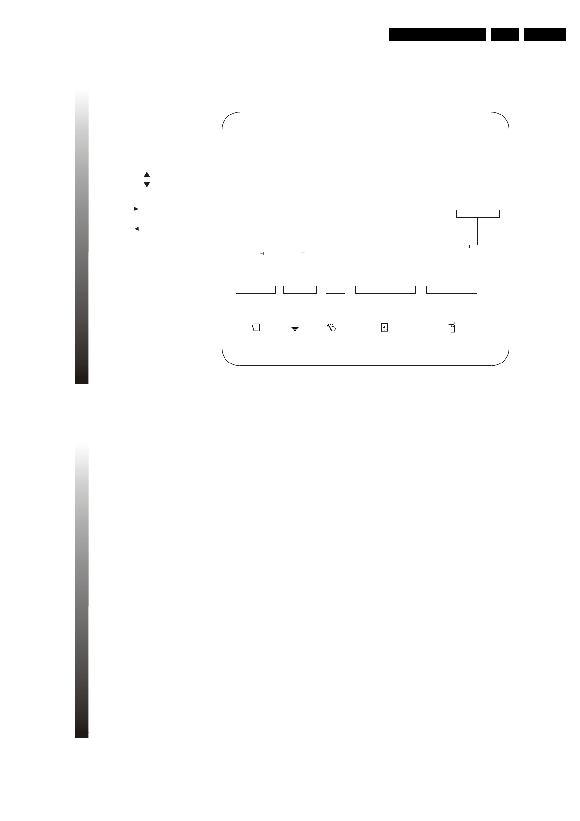
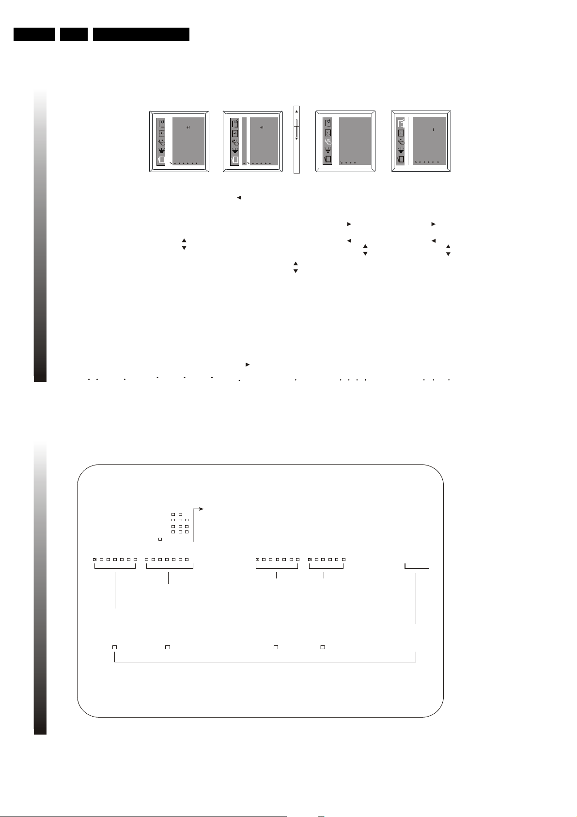
3.1 MAP OF THE ON-SCREEN MENU
PICTURE
FEATURE
TIMER
PRESET
Color 50
Brightness 50
Picture 50
Sharpness 50
Tint 00
DNR On/Off
C. Temp Normal/Warm/cool
Off Time OFF/ONCE/DAILY
0: 00
On Time OFF/ONCE/DAILY
0: 00
Channel 2
Tuner Mode
Cable/Antenna
Clock 0: 00
Tuner Mode
Cable/Antenna
Channel 2
Skipped On/Off
Manual Up/Ddown
Auto Search
Favorite List
Tuner Mode Cable/Antenna
Ch 1 Cable/Antenna 2
Ch 2 Cable/Antenna 3
Ch 3 Cable/Antenna 4
Ch 4 Cable/Antenna 5
Ch 5 Cable/Antenna 6
Language English/French/Spanish
C.Capt Off/CC1/CC2/CC3/C.Mute
AutoLock
Smart timer On/Off
SOUND
Bass 50
Treble 50
Balance 00
Surround On/Off
Volume 50
AVL On/Off
/
13
3. MENU OVERVIEW
EN 9TC4.1U AA 3.
button repeatedly
2. CONNECTIONS
To switch between the TV channels the connected audio/video equipment and DVD press the
TV/AV/DVD
2.3 FREE DISTANCE
The DVD D G TAL OUTPUT jack is optional for use When the set is in DVD state and the receiving
equipment has a coaxial jack they can be connected
For good ventilation of the set it is suggested that a free space of at least 5CM be left between its
12
two sides or back and the wall or anything that may be positioned to block its ventilation holes
Page 10
EN 10 TC4.1U AA3.
4.1 BASIC OPERATION
4.1.1 TURN ON/OFF THE TV
Press POWER button on the main unit to turn on/off the TV set.
If the standby indicator is off, TV is in standby mode.To turn on the TV from STANDBY mode, press POWER
button on the remote control or the CHANNEL UP/DOWN button on the set.
Press POWER button on the remote control to switch the TV to standby mode and the standby indicator
will go out. t is noticeable that PLEASE WA T will appear on the screen before the set goes into standby
mode when in DVD status.
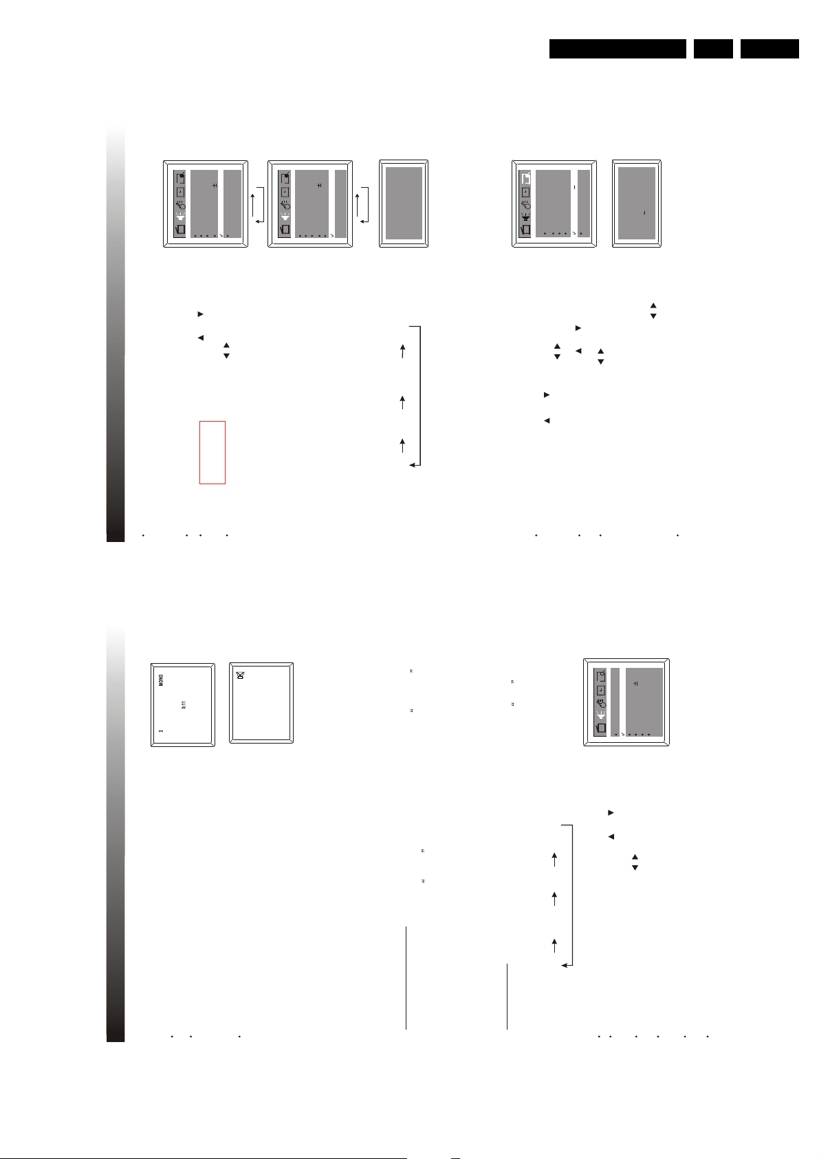
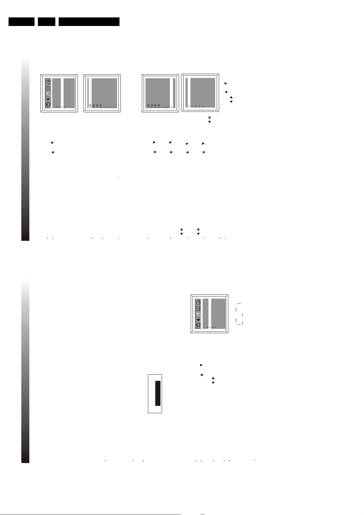
4.1.2 SELECT MAIN MENU
By pressing the MENU button, the main menu bar will appear on the top screen,
and PICTURE menu will be highlighted, which means the pull-down menu PICTURE
is selected and its corresponding sub-menu will be displayed underneath it.
Then press VOLUME UP/DOWN button on the set or on the remote control,
you can move the cursor right or left for selecting other pull-down menus in the main
menu bar.
4.1.3 SELECT SUB-MENU
After selecting a function menu, press CHANNEL UP/DOWN button on the set or CH+
/CH- on the remote control to enter the submenu. Press any of the buttons to move the
cursor up/down to select one item you want to reset with a tick appearing ahead.
4.1.4 ADJUST OPTION
Press VOLUME UP/DOWN button on the set or on the remote control to adjust
the data or status. E.g., the Brightness is adjusted to 65% as shown.
Pressing the MENU button can exit the main menu.
Brightness
Picture
Tint
DNR
C. Temp
505000
Off
Normal
Sharpness 50
Color
50
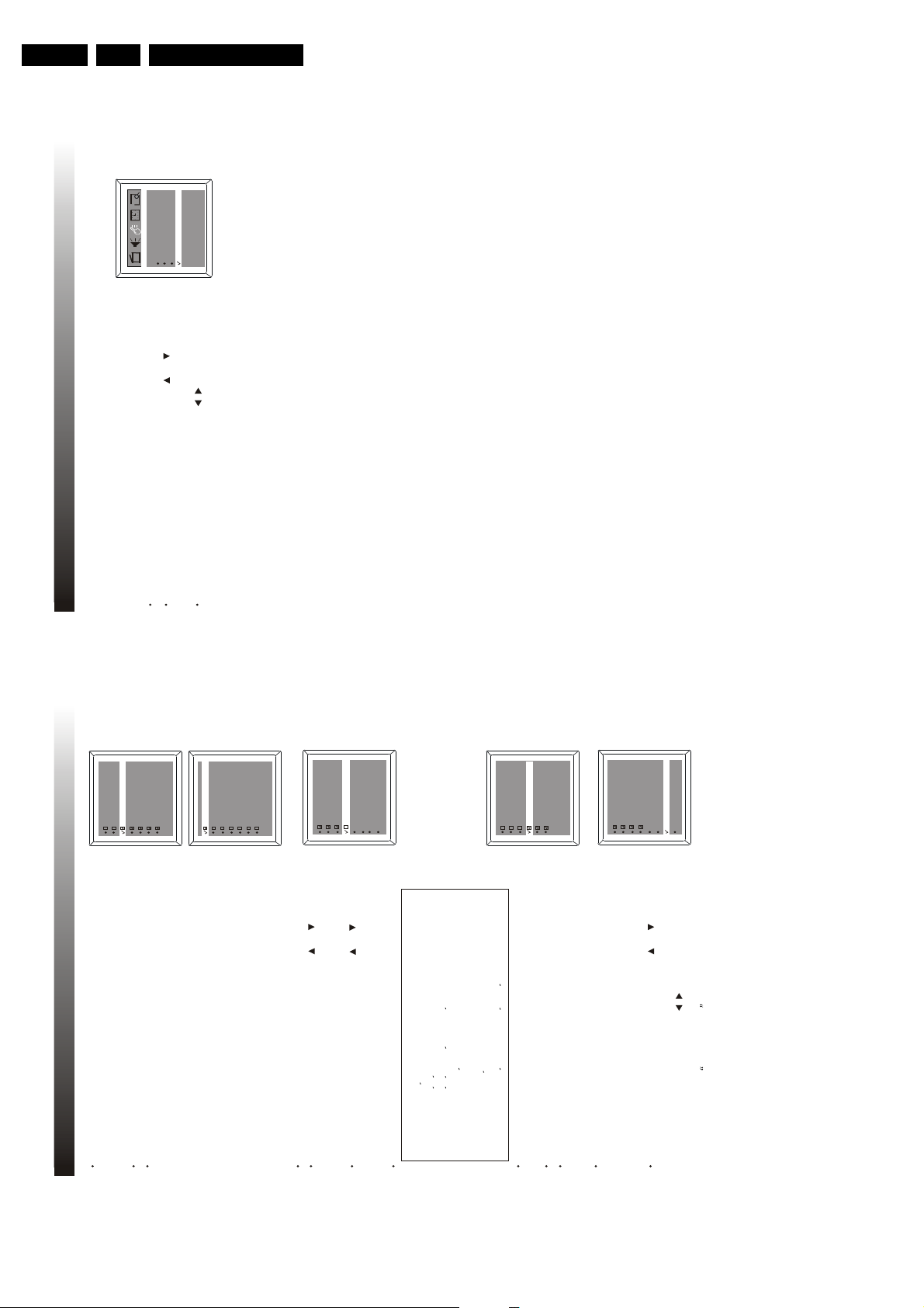
4.1.5 SELECT LANGUAGE
You can set the TV on-screen menu to be English, French, or Spanish.
Press the VOLUME UP/DOWN button on the set or on the remote control
to select your desired language English (or Spanish or French):
Press the CHANNEL UP/DOWN button on the set or CH+ /CH- on the remote
control to select Language.
Activate the FEATURE menu.
Auto Lock
English
Smart Timer Off
C.Capt Off
Language
/
/
/
4.1.6 SELECT TUNER MODE
It is important to know what type of signal-Cable or a normal antenna-you are using. To tell
the TV whether you are using a Cable signal, set the Tuner Mode to Antenna or Cable as
follows:
Press the VOLUME UP/DOWN button on the set or on the remote
control to select Antenna or Cable. Choose Cable if you have Cable TV service.
If you do not have Cable TV service and you connected an antenna to the
TV, choose Antenna.
Activate the PRESET menu.
Skipped
Favorite list
On
2Channel
TunerMode
Auto search
Manual Up
/
Picture
Tint
DNR
C. Temp
50
00
Off
Normal
Sharpness 50
Color50Brightness 50
Brightness
65
Press the CHANNEL UP/DOWN button on the set or CH+ /CH- on the remote
control to select Tun er Mo de.
Antenna
15
4. TV OPERATION
Directions For Use
3. MENU OVERVIEW
---
---
---
---
---
Dialogue
Language
Sexual
Violence
Fantasy V
Content
C8+
GEPG
14+
18+C8ans+
G
13 ans+E16 ans+
18 ans+
Ch lock Off
Tuner Mode Cable/Antenna
Channel 2
Lock Off
GPGPG-13
N/A
R
NC-17
X
NONE F V S L D
TV-Y
TV-Y7
TV-G
TV-PG
TV-14
TV-MA
Content
TV-Y
TV-Y7
TV-G
TV-PG
TV-14
TV-MA
14
MPAA rating
TV parental guidelines
Canadian english rating
Canadian french rating
Block unrated On/Off
Block No Rating On/Off
Master Enable On/Off
Ch lock
AUTO LOCK ----
3.2 MAP OF THE AUTO LOC K MENU
Page 11
Directions For Use
Press the VOLUME UP/DOWN button on the set or on the remote control
to turn on/off the surround sound.
4.2.3 SURROUND SOUND
Activate the SOUND menu.
4.2.4 AVL FUNCTION
The method to turn on/off the AVL function is the same as the surround sound.
On Off
/
Balance : Adjust the sound source position from left speaker to centre to
right speaker as balance is adjusted from L50(-50) to R50(+50).
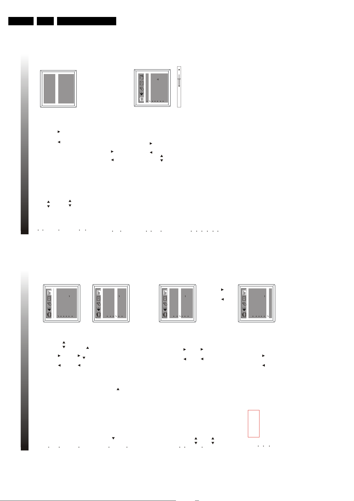
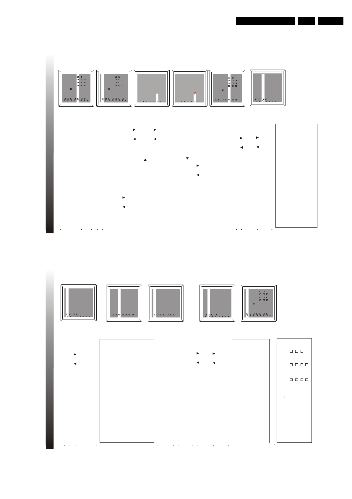
4.3. CHANNEL PRESET
4.3.1 AUTO SEARCH
Please preset all the active channels in your area to the TV set before you enjoy
the TV programs.
Press the VOLUME UP/DOWN button on the set or on the remote control to start
the auto searching when the TV turns black. Then all available channels will be stored
from No.1(Cable mode) or No.2 (Antenna mode) upward in order and the TV remains
black during the whole process. Auto-searching will stop after all the frequency bands
are searched, and the last programme which you select before auto search action will
reappear on the screen. If you want to exit auto search, just press on the remote
control.
First select the signal source. Activate the PRESET menu, press CHANNEL UP/
DOWN button on the set or CH+ /CH- , then the highlight bar is on Tuner Mode.
Press the VOLUME UP/DOWN button on the set or on the remote control to
select Antenna or Cable to be the signal source.
NOTE
Press and hold the MENU button on the front panel of the unit for a few seconds to start auto search action
directly. Besides, if the signal source is Cable, you can get 125 programs, from channel 1 to channel 125,
altogether, however, if the signal source is Antenna, 68 programs from channel 2 to channel 69.
Programming
Please Wait
Ante nna 3
/
/
/
Treb le
Bal ance
50
00
Volu me
Bas s 50
On
50
Surround On
Skipped
Favorite list
On
2Channel
Tuner Mode
Auto Search
Manual Up
Stop
Press CHANNEL UP/DOWN button on the set or CH+ /CH- on the remote control
to select Auto Search.
On Off
Treb le
Bal ance
AVL
50
00
Volu me
Bas s 50
On
50
Surround On
Press the CHANNEL UP/DOWN button on the set or CH+ /CH- on the remote
control to select Surround.
AVL
Voice
4.2.5 SOUND EFFECT SELECTION
Press S.EFFECT button on the remote control to select different sound effect to
allow you to enjoy in the following sequence:
Theatre PersonalVoice
Music
Antenna
4. TV OPERATION
17
EN 11TC4.1U AA 3.
4.1.7 DISPLAY
4. TV OPERATION
Press the DISPLAY button on the remote control to display the current status of the
TV set, such as the current channel No. (or VIDEO input).
Press DISPLAY button again, the current time will be displayed on the middle screen
if you set the current time in the sub-menu of TIMER.
Press MUTE button on the remote control to temporarily turn off the sound and
the sign of MUTE as shown will appear on the screen. Press the MUTE button
once again to restore the sound. Besides, pressing VOLUME UP button
4.1.8 MUTE
also can restore the normal sound output.
NOTE: when the sound of the set is set to 0 or MUTE, no AV audio is output.
This TV is equipped with a feature known as Multi-channel TV Sound or MTS MTS broadcasts
greatly enhance the TV viewing by bringing you programs with high fidelity stereo sound MTS
also provides an extra channel called the Second Audio Program or SAP which broadcasters
can use to transmit a second language for bilingual transmission or for other purposes
Listening to Stereo Sound
4.2 SOUND ADJUSTMENT
4.2.1 MTS STEREO
When the TV is turned on or a channel selection is made, make certain that the word STEREO
f the broadcast signal is not strong enough or clear stereo sound is not available press the MTS
appears on the screen This means that Stereo broadcasting is available You can enjoy stereo sound
from the left and right speakers
When a Mono broadcast is received, no indication is displayed
button to change to mono sound The noise should be eliminated Press it again to return to the stereo
sound
Listening to SAP
When the TV is turned on or a channel selection is made make certain that the letters SAP
SAP Mono+SAPMono
Stereo
appears on the screen This means that Second Audio Program broadcasting is available
Press the MTS button cyclically to select the desired audio setting
Activate the SOUND menu.
4.2.2 BASS, TREBLE, BALANCE ADJUSTMENTS
50
00
50
On
On
Treble
Balance
Surround
AVL
Volu me
Bass 50
/
Press VOLUME UP/DOWN button on the set or on the remote control to
Press the CHANNEL UP/DOWN button on the set or CH+ /CH- on the remote
adjust to your favourable sound, e.g. adjust Bass to 50.
control to select Bass.
The same adjusting procedure is applicable to Volume, Treble & Balance.
Bass : Decrease the low frequency (Bass) by adjusting toward 0,
Notes
increase the low frequency (Bass) by adjusting toward 100.
Treble : Decrease the high frequency (Treble) by adjusting toward 0,
16
increase the high frequency (Bass) by adjusting toward 100.
Page 12
EN 12 TC4.1U AA3.
Press CHANNEL UP/DOWN button on the set or CH+ /CH- on the
remote control to select CH 3 , then press the VOLUME UP/DOWN button
on the set or on the remote control to select channel number you
want to store into this position, such as 8.
Repeat the above procedure to set other four favorite channels.
Press the MENU button three times to exit menu display.
When the highlight bar is on Tuner Mode, press the VOLUME UP/DOWN button
on the set or on the remote control to select Antenna or Cable to be the
signal source, e.g. Cable.
TunerMode
CH 1 Cable 1
CH 2 Cable 2
CH 4 Cable 4
CH 5 Cable 5
CH 3 Cable 8
/
/
Press the ENTER button to display Favorite List menu entries as shown.
4.4 OPERATION OF WATCHING TELEVISION
4.4.1 SELECTING CHANNELS
Press CHANNEL UP/DOWN button on the set or CH+ /CH- on the remote control to change the channel ascendingly/
descendingly.
Use the digit keys on the remote control directly to select the channel.
4.4.2 PICTURE ADJUSTMENT
Activate the PICTURE menu.
Press the CHANNEL UP/DOWN button on the set or CH+ /CH- on the remote control
to select the item, e.g. Brightness..
Press VOLUME UP/DOWN button on the set or o n the remote control
to adjust the picture until you are satisfied, and the Brightness setting will be
automatically stored in the memory of the TV set. The same adjustment
procedure is applicable to color, picture, sharpness, tint and c.temp setting.
Adjust the level of COLOR, BRIGHTNESS, PICTURE, SHARPNESS, TINT and C.Temp
to get the most favorable picture
/
Picture
Adjust for black to white ratio of the picture.
Brightness
Color
Sharpness
Tint
NOTES:
C. Temp
Adjust for color temperature with three choices: normal, warm and cool.
Adjust for picture background level, i.e. the total brightness of picture.
The saturation of color, i.e. the stronger or weaker color of picture.
Adjust for detailed level of picture.
Adjust for color tune only when watching NTSC picture.
Picture
Tint
DNR
C. Temp
50
00
Off
Normal
Sharpness 50
Color50Brightness 50
Brightness
65
4. TV OPERATION
19
Directions For Use
2Channel
On
Antenna
Skipped
Tuner Mode
First select the signal source. You can refer to the method introduced in AUTO
SEARCH to realize this step.
4.3.2 MANUAL TUNE
4. TV OPERATION
Press the CHANNEL UP/DOWN button on the set or CH+ /CH- on the remote control
You can store the channel at your favorite position number by manual tune.
Auto search
Manual Up
/
to select Channel, then press VOLUME UP/DOWN button on the set or on the
remote control to select the channel number at which you want the searched channel to
Favorite list
Press the CHANNEL UP/DOWN button on the set or CH+ /CH- on th e remote control
be stored.
Antenna
Tuner Mode
2Channel
On
Skipped
Manual Up
Favorite list
Auto search
Antenna
Tuner Mode
2Channel
Manual Up
Skipped On
Favorite list
Auto search
Antenna
Tuner Mode
2Channel
Skipped On
Manual Up
Auto search
Favorite list
18
/
to select Manual, then press VOLUME UP button on the set or o n the remote control to
start searching upward; or press VOLUME DOWN button on the set or o n the remote
control to start searching downward.
To stop manual search, press the VOLUME DOWN button on the set
or on the remote control when searching upward, or press the
VOLUME UP button on the set or on the remote control when
searching downward.
When channel searching is completed, press the MENU button to quit
NOTE
menu, or menu will quit after a few seconds without further action.
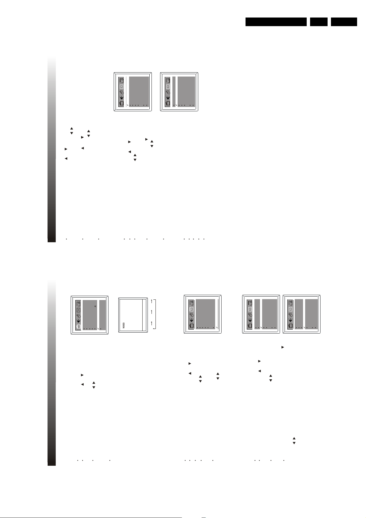
4.3.3 PROGRAM SKIPPED
After the auto search, some fault stations may be memorized because the TV
Activate the PRESET menu.
Press the CHANNEL UP/ DOWN button on the set or CH+ /CH- on the remote
station broadcasts with different frequencies for your and your neighborhood regions.
control to select Channel, then press the VOLUME UP/DOWN button on the set or
These additional stations are weak and should be removed from channel memory.
on the remote control to select the channel No. you want to skip, e.g. 18.
Press the CHANNEL UP/ DOWN button on the set or CH+ /CH- on the remote
/
control to select Skipped, then press the VOLUME UP/DOWN button on the set or
on the remote control to turn on or off skipped function.
Note:
A skipped channel can not be accessed by pressing CHANNEL UP/ DOWN button on the set or CH+ /CH-
on the remote control. However, you can get it by means of digit buttons.
Activate the PRESET menu.
Press the CHANNEL UP/DOWN button on the set or CH+ /CH- on th e remote control
by pressing FAV. button.
to select Favorite List.
4.3.4 FAVORITE CHANNEL SETTING
You can store five favorite channels in memory and preview those channels
Page 13
Directions For Use
On Time
Channel
Tune r M ode
0:00
2
Off
0:00
Clock
9:30
Antenna
OffOff Time
4.6.3 OFF TIMER
To turn off the TV on specified time, off timer function will be useful to you.
Activate the TIMER menu.
Press the CHANNEL UP/DOWN button on the set or CH+ /CH- to select Off Time.
Press the VOLUME UP/DOWN button on the set or on the remote control to
select among Daily, Once, Off.
If you select DAILY or ONCE, press CHANNEL DOWN button or CH- to 0:00 beneath
Off Time, then press the VOLUME UP/DOWN button on the set or on the remote
control to set the Off time, e.g 22:50.
Press menu button to exit menu display, or menu will quit after a few seconds
without further operation.
NOTES
Off : The timer is set to off and will not operate.
Once : The timer is set to alarm only one time.
/
/
Channel : This is the channel the TV will display at ON time.
Tuner Mode : This is the mode the TV will display at ON time.
Daily :The timer is set to alarm at that time everyday until otherwise adjusted
Press the CHANNEL UP/DOWN button on the set or CH+ /CH- to select
Channel, then press the VOLUME UP/DOWN button on the set or on the
remote control to select your desired channel No., e.g 11.
Press the CHANNEL UP/DWON button on the set or CH+ /CH- on the remote control to
select Tuner Mode, then press the VOLUME UP/DOWN button on the set or on the
remote control to select Antenna or Cable to be the signal source.
/
Press the MENU button to exit the menu display, or menu will quit after a
few seconds without further operation.
/
On Time
Channel
TunerMode
2
Off
0:00
Clock
9:30
Antenna
Off Time
0:00
Off
4. TV OPERATION
21
EN 13TC4.1U AA 3.
Color50Brightness 50
50
Picture
Sharpness 50
00
Tint
Normal
C. Temp
DNR Off
2
OffOff Time
Off
0:00
0:00
On Time
Antenna
Channel
TunerMode
9:30
Clock
DVD
VIDEO
TV
turned off into standby mode.
/
/
2
OffOff Time
Off
0:00
0:00
9:30
Antenna
Clock
Channel
TunerMode
On Time
2
OffOff Time
Off
0:00
0:00
9:30
Antenna
Clock
Channel
TunerMode
On Time
20
/
/
Press the VOLUME UP/DOWN button on the set or on the remote control
Activate the TIMER menu.
Press the CHANNEL UP/ DOWN button on the set or CH+ /CH- on the remote
control to select On Time.
to select among OFF, ONCE, DAILY./If you select DAILY or ONCE, press the CHANNEL DOWN button on the set or CH- on the
remote control to select to 0:00 beneath On Time, then press VOLUME UP/DOWN button on
4.4.3 DNR FUNCTION
Turn this function to ON mode to get a clearer picture when the signal is poor.
4. TV OPERATION
Activate the PICTURE menu.
Press VOLUME UP/DOWN button on the set or o n the remote control
Press the CHANNEL DOWN button on the set or CH+ /CH- on the remote control to
select DNR.
to turn it on or off.
When DNR is turned to On mode, the Sharpness of the picture
NOTE
will be decreased.
4.5 TV/AV/DVD SELECTION
Press TV/AV/DVD button repeatedly to select the TV, AV or DVD signal sources.
When the set is in DVD state, you can playback discs(see the particular instructions
in DVD section). This TV set has one composite video input.
4.6 TIMER FUNCTION
Timer function is provided by the microcomputer of TV set. Once it is set, the ON/OFF
time and time displaying functions can start functioning. The TV set will keep the correct
time as long as the main power is on, even if the TV has been
4.6.1 CURRENT TIME SETTING
Press the VOLUME UP/DOWN button on the set or on the remote control
Activate the TIMER menu.
Press the CHANNEL UP/DOWN button on the set or CH+ /CH- on the remote
control to select Clock.
to set the current time , e.g. 9:30.
If you want to change hour value directly, press ENTER to select hour part, then
repress the VOLUME UP/DOWN button on the set or on the remote control to
set its value. Afterwards, press ENTER to save the setting and simultaneously exit
hour setting. The method is also suitable for Off Time and On Time.
4.6.2 ON TIMER
To turn on the TV everyday on specified time with your desired channel, on timer
function provides a convenient way to do it.
the set or on the remote control to set the ON time, e.g 9:59.
Page 14
EN 14 TC4.1U AA3.
6.1 CH LOCK SETUP
CH LOCK enables parents to prevent their children from watching inappropriate channels. If the locked
channel is selected to watch, message appears on the TV screen with a blue background
and the sound is mute.
'channel lock on'
After inputting the password for Auto Lock, you can enter Auto Lock setup menu.
Press the CHANNEL UP/DOWN button on the set or CH+ /CH- on the remote
control to select CH lock and press the ENTER button, then CH lock set up menu is
activated.
Press the CHANNEL UP/DOWN button on the set or CH+ /CH- on the remote
control to select Tuner Mode, and press the VOLUME UP/DOWN button on the set or
on the remote control to select Antenna or Cable to be the signal source.
Press the CHANNEL UP/DOWN button on the set or CH+ /CH- on the remote
control to select Channel, and press the VOLUME UP/DOWN button on the set or
on the remote control to select a channel you want to lock.
Press the CHANNEL UP/DOWN button on the set or CH+ /CH- on the remote
control to select Lock, and press the VOLUME UP/DOWN button on the set or
on the remote control to select On.
If you want to lock several other channels, please repeat the above steps.
After setting all channels you want to lock, press the CHANNEL UP/DOWN button on the set or CH+ /CH- on
the remote control to select CH lock, and press the VOLUME UP/DOWN button on the set or on the remote
control to select On. It means all channels you selected have been locked.
TV parentalguidelines
Canadian englishrating
Canadian frenchrating
MPAArating
CH lock On
TunerMode
Cable
Channel 2
Lock On
AUTO LOCK function enables parents to prevent their children from watching inappropriate channels
or inappropriate material on TV.
NOTES
When the FEATURE menu is activated and the highlight bar is on Auto Lock
you can change the password following the steps
below:
, or the
V-chip function is already activated,
Press the CHANNEL UP button on the set and the VOL.+ button on the remote
control simultaneously.
TV parentalguidelines
Canadian englishrating
Canadian frenchrating
Block unrated off
Block NoRating off
MPAArating
Activate the FEATURE menu.
Press the CHANNEL UP/DOWN button on the set or CH+ /CH- on the remote
control to select Auto Lock, press ENTER to input a four-digit password, then you
can go on setting up Auto Lock. (0000 is the default password).
Input a new four-digit password with the digit keys on the remote control, and press
the ENTER button. Then Auto Lock function is activated and your new password is
set successfully.
Please remember the password and don t let children know the password.
/
/
/
6 2 V-CHIP SETUP
This TV has a built-in V-CH P, which can reads the ratings for programming (except for news and sports
programs, unedited movies on premium cable channels, and emergency broadcast system signals),
then denies access to programming if the programs rating meets the limitations you select. n this case,
message appears on the TV screen together with a blue background and the
sound is mute.
'V-CH P block active...'
NOTE
Programming may be rated by the Motion Picture Association of America(MPAA)or according to the
Television Parental Guideline, Canadian English Rating or Canadian French Rating.
Master Enable off
CH LOCK
English
Smart Timer Off
C.Capt Off
Language
Auto Lock
/
NOTE
When CH Lock is on, there is no existence of PRESET submenu.
Block unrated off
Block NoRating off
Master Enable off
CH LOCK
6. AU TO LOC K F UNCTIO N
23
Directions For Use
You may view labeled (cc)TV programs, movies, news, prerecorded tapes, etc with either a dialogue
caption or text display added to the program
CAPTION MODE
5. CLOSED CAPTION
1 Characters can be displayed on the TV screen when the received broadcast signal contains the
caption signal
2 There are three modes for the caption display
Paint-on mode Displays input characters on the TV screen immediately
Pop-on mode Once characters are stored in memory it is displayed all at once
Roll-up mode Displays the characters continuously by scrolling (max 4 lines)
f the received broadcast signal does not contain the caption signal or text signal but the
To display the text on the screen by scrolling (max 7 lines)
TEXT MODE
NOTE
'
's
The caption or text characters will not be displayed while the menu display or function display
caption mode or text mode is selected no change will occur
When your TV receives a special effects playback signal (i e Search Slow Still) from a VCR s
video output channel (Ch3 or Ch4) your TV may not display the correct caption or text
Captions and texts may not match the TV voice exactly
is shown
f you see this screen
CC3
C.Mute
Off
CC1 CC2
English
Auto Lock
C.Capt Off
Language
Smart Timer Off
22
/
Activate the FEATURE menu.
Press the CHANNEL UP/DOWN button on the set or CH+ /CH- on the remote
Press the VOLUME UP/DOWN button on the set or on the remote control
control to select C.Capt.
to select a caption or text channel you want to watch.
To cancel the caption or text mode, just set C.Capt to off.
Press the menu button twice to exit menu, or menu will quit after a few seconds
A black box is shown on the TV screen this means that your TV is set to text mode
5.1 CLOSED CAPTION OPERATION
To clear screen select C Capt to Off
without further operation.
When C.Mute is selected and the MUTE function is activated(by''
pressing the MUTE button on the remote control), the caption
transmitted in channel CC1 will be displayed on the TV screen.
NOTE
Page 15
Directions For Use
When you select a rating to block, e.g. TV-PG, the higher rating(TV-14
and TV-MA) and their sub-ratings will be blocked automatically, while the
lower rating (TV-Y, TV-Y7, TV-G) and their sub-ratings will be unblocked
automatically shown as Fig.1.
In Fig2, you can see the sub-rating setup situation. No tick in the frame
under F, V, S, L D , which means <unblock> or < view>.
When you blockY rating, all the ratings will be blocked automatically.
To unblock all the ratings, select N/A and press the ENTER button.
PROGRAM
TV-Y7, TV-PG, TV-14 and TV-MA include sub-ratings. When you block a
rating, its sub-ratings will be blocked automatically. But you can unblock
the sub-ratings individually.
1. In the menu shown as Fig.1, press the UP/DOWN button on the
set or CH+ /CH- on the remote control to select the item Content.
2. Press the ENTER button to enter the sub-rating setup menu.
3. Press the CHANNEL UP/DOWM button on the set or CH+ /CH- on the
remote control to select a rating category, e.g. TV-14 as Fig.3.
4. Press the VOLUME UP button on the set or on the remote control to
start a sub-rating selection.
5. Press the CHANNEL UP/DOWN button on the set or CH+ /CH- on the
remote control to select your desired sub-rating, e.g. Language. Then press
the ENTER button to turn it <block> or <view>. If you select <view>, this sub
-rating in rating TV-14 is unblocked.
6.You can unblock several other sub-ratings of this rating category by
repeating the step5.
7. Press VOLUME DOWN button on the set or on the remote control to
exit the sub-rating selection of this category. By pressing CHANNEL UP
/DOWN button on the set or CH+ /CH- on the remote control , you can
select other rating category, and repeat step4, 5 to set the sub-rating
<block> or <view>.
8. For example, if you only set the sub-ratings of TV-14 as Fig4, then press
the Menu button to go back to the previous screen, the display will be
shown as Fig.5, the sub-ratings(V, S, L) have been unblocked..
Fig.1
Fig.2
TV-Y7
TV-G
Content
TV-14
TV-MA
Violence
Sexual
Language
Dialogue
TV-Y
Fantasy V
TV-PG
TV-Y7
TV-G
Content
TV-14
TV-MA
Violence
Sexual
Language
Dialogue
Block
TV-Y
Fantasy V ---
TV-PG
Fig.3
Block
Block
Block
TV-Y7
TV-G
Content
TV-14
TV-MA
Violence
Sexual
Language
Dialogue
TV-Y
Fantasy V
TV-PG
TV-Y7
TV-G
Content
TV-14
TV-MA
Violence
Sexual
Language
Dialogue
View
TV-Y
Fantasy V ---
TV-PG
Fig.4
View
View
Block
TV-Y
TV-Y7
TV-G
NONE F VSLD
TV-PG
TV-14
Content
TV-MA
Fig.5
6.2.3 CANADIAN ENGLISH RATING SETUP
Activate the Auto Lock setup menu.
Press the CHANNEL UP/DOWN button on the set or CH+ /CH- on the remote
control to select Canadian English rating, then press the ENTER button to enter the
Canadian English rating setup menu.
Press the CHANNEL UP/DOWN button on the set or CH+ /CH- on the remote
control to select the your desired item and press the ENTER button to block it.
TV-Y
TV-Y7
TV-G
NONE F V S L D
TV-PG
TV-14
Content
TV-MA
TV-Y
TV-Y7
TV-G
NONE F V S L D
TV-PG
TV-14
Content
TV-MA
TV parentalguidelines
Canadian frenchrating
Block unrated off
Block NoRating off
MPAArating
Canadian englishrating
Master Enable off
CH LOCK
6. AU TO LOC K F UNCTIO N
25
All the Canadian English ratings shall be shown in the table below:
Selection Rating Category Explanation
E Exempt
C Children
C8+ Children eight years and older
G
General programming, suitable for all audience
PG Parental guidance
14+ Viewers 14 years and older
NOTE
18+ Adult programming
EN 15TC4.1U AA 3.
6.2.1 MPAA RATING SETUP
6. AU TO LOC K F UNCTIO N
MPAArating
Activate the Auto Lock setup menu. Then the highlight bar is on MPAA rating as shown.
TV parentalguidelines
Canadian englishrating
Press ENTER button to enter the MPAA rating setup menu.
Canadian frenchrating
Master Enable off
Block unrated off
Block NoRating off
CH LOCK
Press the CHANNEL UP/DOWN button on the set or CH+ /CH- on the remote
control to select the item you want to block, then press ENTER button to confirm.(the
tick in the frame shows that this rating has been blocked).
NOTE
All the MPAA ratings shall be shown in the table below:
G
N/A
G General Audience
PG Parental Guidance Suggested
Selection Rating Category Explanation
PG-13
R
NC-17
PG
PG-13 Unsuitable for children under 13
R Restricted; under 17 requires
GPGPG-13
N/A
R
NC-17
When you select a rating to block, e.g. PG, the higher rating(PG-13, R,
NC-17 and X) will be blocked automatically, while the lower rating (G) will
be unblocked automatically.
X
When you block G rating, all the ratings will be blocked automatically.
Activate the Auto Lock setup menu.
To unblock all the ratings, select N/A and press the ENTER button.
6.2.2 TV RATING SETUP
X
NC-17 No oneunder 17 admitted
X Mature Audience Only
accompanying parent or adult
guardian
TV-MA
TV-Y
TV-Y7
TV-G
NONE F VSLD
TV-PG
TV-14
Content
MPAArating
Canadian englishrating
Canadian frenchrating
TV parentalguidelines
Block unrated off
Master Enable off
Block NoRating off
CH LOCK
TV-Y7 TV-PG TV-14 TV-MA
Appropriate for all childrenY7Appropriate for children seven and older
General Audience
Parental Guidance suggested
Unsuitable for children under 14MAMature Audience Only
Y
G
PG
Selection Rating Category Explanation
Press the CHANNEL UP/DOWN button on the set or CH+ /CH- on the remote
control to select TV parental guidelines, then press the ENTER button to enter the TV
rating setup menu as shown.
Press the CHANNEL UP/DOWN button on the set or CH+ /CH- on the remote
control to select the item you want to block, then press the ENTER button to confirm.
NOTE
All the TV ratings shall be shown in the table below:
14
F (Fantasy Violence)
All the sub-ratings shall be shown in the table below:
V (Violence)
S(sexual situation)
L(Course Language)
D(Suggestive Dialogue)
24
Page 16
EN 16 TC4.1U AA3.
7.1 SMART TIMER
If Smart Timer is turned on, the TV will turn off automatically after 4 hours without
any operation on the set.
Activate the FEATURE menu.
Press the VOLUME UP/DOWN button on the set or on the remote control
to turn it on or off.
Press the CHANNEL UP/DOWN button on the set or CH+ /CH- on the remote control
to select Smart Timer.
/
Auto Lock
English
C.Capt Off
Language
Smart Timer Off
7. SUPER FUNCTION
27
Directions For Use
GEPG
C
C8+
When you select a rating to block, e.g. C8+, the higher rating(G,PG, 14+
18+) will be blocked automatically, while the lower rating (C) will be
unblocked automatically.
When you block C, all the ratings will be blocked automatically.
6. AU TO LOC K F UNCTIO N
14+
18+
C
C8+
To unblock all the ratings, select E and press the ENTER button.
GEPG
TV parentalguidelines
Canadian englishrating
MPAArating
14+
18+
Activate the Auto Lock setup menu.
6.2.4 CANADIAN FRENCH RATING
Canadian frenchrating
Block unrated off
Block NoRating off
Press the CHANNEL UP/DOWN button on the set or CH+ /CH- on the remote
control to select Canadian french rating, then press the ENTER button to enter the
Canadian french rating setup menu.
Press the CHANNEL UP/DOWN button on the set or CH+ /CH- on the remote
Master Enable off
control to select your desired item and press the ENTER button to block it.
CH LOCK
NOTE
Selection Rating Category Explanation
All the Canadian French ratings shall be shown in the table below:
GeneralG
General- Deconseille aux jeunes enfants
13 ans + Gette emission peut convenir aux enfants
E Exemptees
8 ans +
de moins de 13 ans
TV parentalguidelines
Canadian englishrating
MPAArating
8ans+E16 ans+
G
13 ans+
18 ans+
Canadian frenchrating
Block unrated off
Master Enable off
Block NoRating off
CH LOCK
26
/
Gette emission est reservee aux adult
Gette emission ne convenient pas aux moins de 16 ans
16 ans +
18 ans+
When you select a rating to block, the higher rating will be blocked
automatically.
When you block G, all the ratings will be blocked automatically.
To unblock all the ratings, select E and press the ENTER button.
6.3 ACTIVATE V-CHIP
When all your limits in four places (MPAA rating, TV parental guidelines, Canadian
English rating and Canadian French rating) are set, return to Auto Lock setup menu
by pressing the MENU button. Here Auto Lock offers various blocking options from
which to choose:
Press the CHANNEL UP/DOWN button on the set or CH+ /CH- on the remote
control to select Block unrated(or Block No Rating, Master Enable). Press the
VOLUME UP/DOWN button on the set or on the remote control to select On
or OFF.
Mater Enable This is the master switch for Auto Lock. When ON, all the blocking
/censoring you have set is enabled.When Off, all the blocking/censoring is disabled.
Block Unrated All unrated programs (based on movie ratings or TV ratings) will be
blocked if this feature is ON and Master Enable is ON.
Block No Rating All programs with NO content advisory can be blocked if this feature
is ON and Master Enable is ON.
Page 17
Directions For Use
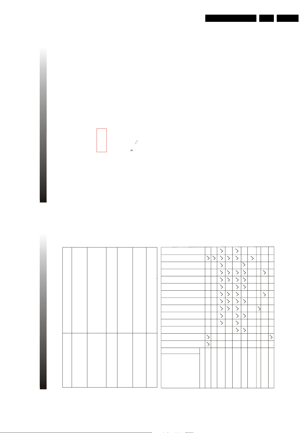
MAIN UNIT
TV Receiving System
AV Colour System
Antenna Input VHF/UHF/CATV 75OHM Unbalanced (F-Type)
Video Input/Output 75-ohm 1 0Vp-p RCA
Audio Input 10k ohm 0 5 Vrms high impedance
Audio Output 1k ohm 0 5 Vrms
Audio Output Power
Operating V oltage
60Hz
Power Consumption
Dimensions
X X
MM
Net Weight
INFRA-RED REMOTE CONTROL
Features Full Function Remote Control
Effective Distance Power 8 meters
Power Supply DC 3V (two batteries size AAA)
PACKING LIST
Product is subjected to change without notice.
98W
28 kg
510
484 491
4W+4W
120V
NTSC-M
1 TV set - one set
2 Remote Control Handset - one set
3 Operation Manual - one pc
PAL4 43 NTSC3 58 & NTSC4 43
Closed Caption System
15 119/FCC
Channel Coverage VHF
UHF
CATV
2-13
14-69
2-13 a-w w+1~W+84 A-5~A-1 5A
Tuning system
181 Channel Frequency synthesized tuning system
Channel Access
Direct Access Keyboard
Programmable Scan Up/Down
CRT Size 54CM(Diaglonal)
Language of OSD
English French and Spanish
9. SPECIFICATION
29
EN 17TC4.1U AA 3.
Possible Remedy
Closed Caption Problem
Sometimes a performance problem can be easily solved by checking apparent but often overlooked
possibilities.
Before arranging for service,check these items. It could save your time and money.
8. TROUBLESHOOTING
You are watching a live broadcast and spelling errors made by the closed
captioning production company pass through uncorrected. A prerecorded
program will not show any misspelled words because of the normal time
available for editing the captions.
Captions that are delayed a few seconds behind the actual dialogue are
common for live broadcast. Most captioning production company can
Interference caused by building, power lines, thunderstorms, etc. may
display a dialogue to maximum of 220 words per minute. If a dialogue
cause scrambled or incomplete captions to appear.
exceeds that rate. Selective editing is used to ensure that the captions
remain up-to-date with the current TV screen dialogue.
Broadcasters may at times use a time compression process to the actual
program so that additional advertisting time can be given.Since the decoder
cannot read the compressed information, captions will be lost.
You are in the TEXT mode. Select CAPTION mode or CAPTION (OFF)
The videotape was either an illegal copying or the tape duplicating company
accidentally left out the captioning signals during the copying process.
My TV is showing captions that are
misspelled.
My TV will not show the text in its entirety
or there is a delay of what is being said.
My TV screen show a black box on
My prerecorded videotape does not show
My program guide listed a TV show as being
closed captioned, but none of the captions
My caption are scrambled with white boxes
on the screen.
were displayed.
certain channels.
any caption. The tape box mentions it being
closed captioned.
Weak picture
No color
No power
PROBLEM
Picture blured
No picture or sound
Picture OK,sounds poor
Sounds OK,picture poor
Ghosts in picture
picture
Lines or streaks in
channel
Poor reception on some
Picture rolls vertically
Picture distorted
Bars on screen
work
Remote control doesn't
trouble.Is TV in standby mode?
Is the power switch turned on?
Try a new channel, if OK, possible
station
Is antenna connected to termina
POSSIBLE REMEDY
Is TV power cord connected.
on the jack of the set?
If outside antenna is being used,
check for broken wire.
Check for local interference.
Turn off the power switch and
then turn it on after one minutes.
28
Adjust CONTRAST&BRIGHTNESS
control
Adjust color control.
Check batteries in remote control
Page 18
EN 18 TC4.1U AA3.
31
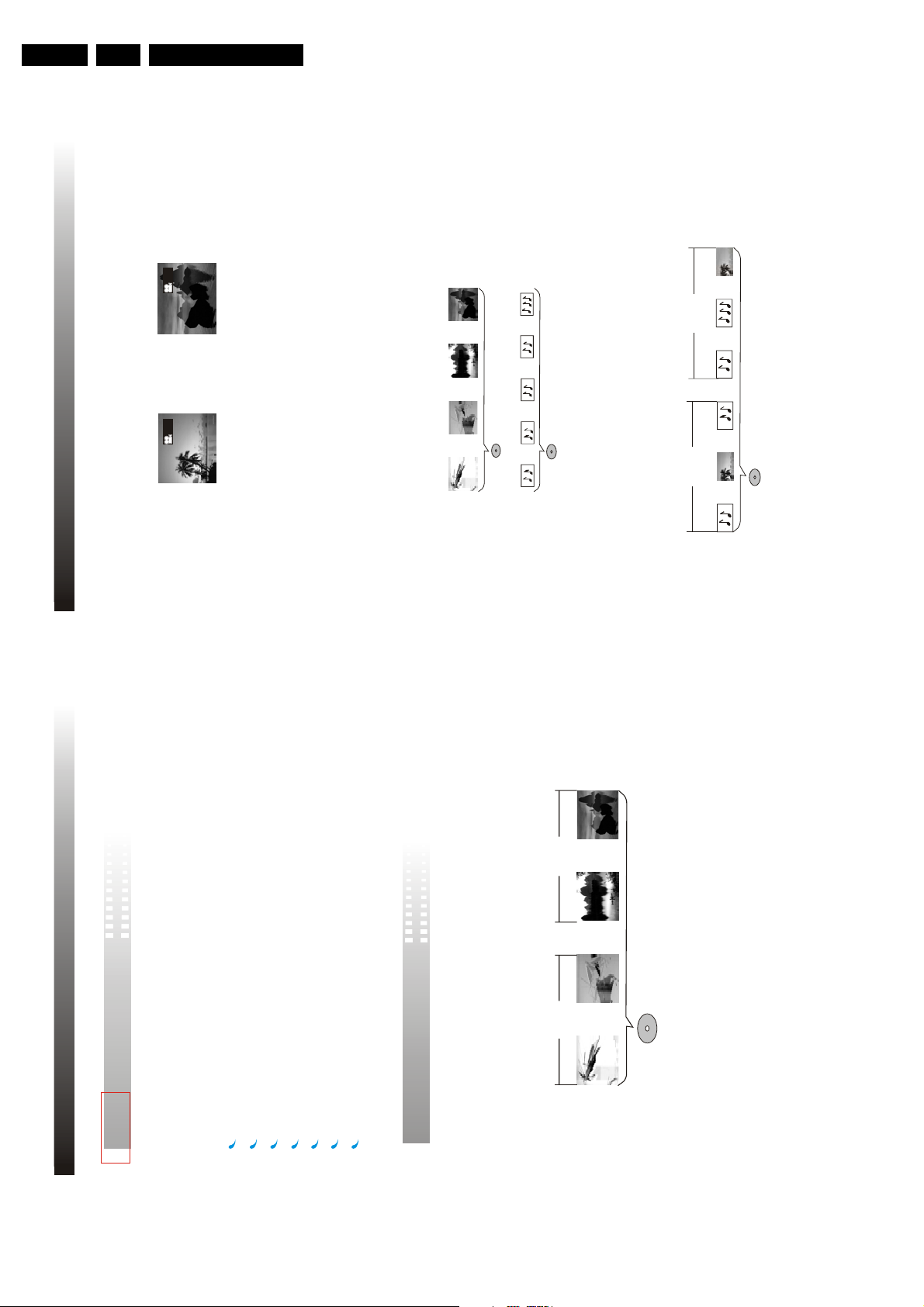
You can select the expected subtitle language or turn subtitles off when watching movies or discs that
have multi-language subtitles recorded on them
SVCD/VCD/CD are divided into a number of tracks A track may contain a number of index points
occasionally, which effectively divides the track up into several parts
CD DISCS
SVCD/VCD DISCS
1/
4
2/
4
You can view scenes from different camera angles when watching movies or other media with multiple
angle playback available
You can select the expected language on when watching movies or discs that have multiple languages
and/or audio soundtracks recorded on them
MP3 (MPEG1 audio layer 3) is a compressed audio file format Files are recognized by their file
extension " mp3" or " MP3" JPEG is a compressed image file format Files are recognized by their file
extension " jpg"
or " JPG" Please refer to MP3 playing on page 32 and JPEG playing on page 33 for
details
MP3
FOLDER1 FOLDER2
TRACK1 TRACK2PICTURE1 TRACK1 TRACK2 PICTURE1
TRACK1 TRACK2 TRACK3 TRACK4
TRACK1 TRACK2 TRACK3 TRACK4 TRACK5
Multi-angle
Multiple languages
Multi-language subtitles
SVCD/VCD/CD
MP3/JPEG
11. OPERATION GUID
Directions For Use
Introduction of product functions
This appliance adopts Taiwan MTK latest-generation DVD decoder chip that integrated functions of
10. INTRODUCTION
decoder and server t supports full functional DVD playback modes including 8 languages, 32 sub-
titles and 9 angels The appliance can play DVD, DVD+RW, DVD+R, super VCD, VCD, DVCD, CD,
CDR discs n addition, MP3 and Picture CD are also playableand CDRW
The player has the following features
24-bit/192KHz audio D/A converter with high-quality DVD audio output
The latest laser-head with super error-correction capability
10-bit/27MHz video D/A converter with up to 500-line horizontal resolution
Multi-angle playback selection
16 9 and 4 3 TV screen aspect ratio support
Multi-lingual playback
Parental Lock Level control system
Differences in disc composition
All discs are divided into smaller, more manageable sections so that you can find specific content
more easily DVD discs are divided into one or more titles Each title may be further divided into
several chapters Occasionally, a chapter may contain index points, effectively dividing the chapter
DVD
up into several parts, too
TITLE2
TITLE1
CHAPTER1 CHAPTER2 CHAPTER1 CHAPTER2
30
DVD DISCS
Page 19
Directions For Use
F V.
Note This operation is only available for VCD discs of version 2 0
and above
TITLE
Press T TLE button to access the title menu of the disc
Select the item with the CURSOR buttons then press
ENTER to start playback
Or press the NUMBER buttons to play the corresponding
chapter directly
Notes
This operation is only available for DVD discs Some discs may directly begin playback after data reading
Press MENU/PBC button and the main menu of the disc will
be displayed on the TV screen Menu screen varies with
the disc
Select the item with the CURSOR buttons then press
ENTER to start playback
Or press the NUMBER buttons to play the corresponding
chapter directly
MENU/PBC
When a DVD disc is played
When a VCD disc is played
Press MENU/PBC button to select PBC on or off When PBC is on,
a menu will be displayed for some discs
Press the NUMBER buttons to play the corresponding chapter
directly f you do not choose any one, it will playback from the first
one sequentially
During playback when PBC is off, press MENU/PBC to change PBC
back to on and the disc will go back to its beginning When PBC is on
and during playback of the first selected one you press NUMBER
buttons to select another chapter, you will see PBC OFF appear left
top, which means PBC becomes off automatically PBC OFF will not
appear again later
33
OPEN/CLOSE
Press to open or close the DVD tray
Press OPEN/CLOSE button or on the set when in AV or
TV status, it will turn to DVD status automatically
DVD10+
Press DVD10+ button to select two or three-digit item The times
of pressing this button decide the first bit Anyway it will be limited
by the sum of items
For example, press DVD10+ button once, 1- will be displayed,
press any digit key, take 5, the 15th item will be selected and played
Press DVD10+ button twice, 2- will be displayed, press any
digit key, take 5, the 25th item will be selected and played
13. BASIC OPERATION
EN 19TC4.1U AA 3.
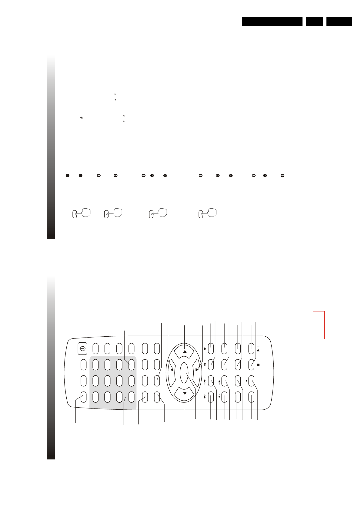
12. DIAGRAM OF REMOTE CONTROL
POWER
TV/AV/DVD
MUTE
OPEN/CLOSE
1
C SYS.
SLEEP
3
6
21
5
4
21
S.EFFECT
9
8
7
VOL+
PICTURE/DEL.
MTS
D SPLAY
0
RECALL
TITLE
FAV.
DVD10+
2
3
VOL-
MENU
MENU/PBC SETUP
6
5
4
ENTER
6
6
8
8
6
SEARCH
SK P
SCAN
7
9
14
13
12
11
10
MODE
R/L
SLOW
9
16
STOP PLAY/PAUSE
SUBT TLE ZOOM
A B
REPEAT
REPEAT
LANGUAGE ANGLE
18
19
17
16
15
/
20
15 STOP
16 SLOW
17 LANGUAGE
8 SK P
9 SCAN
10 SEARCH MODE
1 OPEN/CLOSE
2 DVD10+
3 T TLE45
18 ANGLE
19 REPEAT
20 REPEAT A-B
21 D SPLAY
11 R/L
12 ZOOM
13 SUBT TLE
14 PLAY/PAUSE
MENU/PBC
SETUP
6 CURSORS
7 ENTER
32
Page 20
EN 20 TC4.1U AA3.
For VCD discs
Note The above displayed information is related to the setting and content of the disc
SINGLE ELAPSED
SINGLE REMAIN
PRO LOGIC OFF
DISPLAY OFF
Press or button on remote control to fast search
forward or reversely
Press PLAY/PAUSE button to resume normal playback speed
SCAN SCAN
Note SLOW REVERSE function is only available for DVD discs
SCAN
SLOW
12
14
18 116
12
1 4
18
116
Press PLAY/PAUSE button to resume normal playback speed
Press or button on remote control to play the disc in
forward or reverse slow motion
SLOW SLOW
Press button on remote control to skip forward to the next
chapter
Press button on remote control once to skip back to the
current chapter(DVD) or track (VCD or CD)
SKIP
SKIP
SKIP
Press button on remote control twice to skip backward to
the beginning of the previous chapter or track
SKIP
Note playback resumes in a normal speed after skipping to the beginning of a chapter
35
2X
4X 8X 16X 32X
2X
4X 8X 16X 32X
For DVD discs
TITLE ELAPSED
TITLE REMAIN
CHAPTER ELAPSED
CHAPTER REMAIN
DISPLAY OFF
13. BASIC OPERATION
Directions For Use
13. BASIC OPERATION
VCD 1 0 and 1 1 discs are only available for sequential
playback mode Sequential playback mode will be accessed
Sequential playback
Under sequential playback mode, you can press the NUMBER
buttons to play the corresponding chapter directly Number
buttons are available during playback
directly after disc reading for these discs
With some discs, playback may start directly after data reading
Note The sequential playback mode is only available for
VCD and SVCD
Example: AUDIO 1/4:AC-3 5.1CH CHINESE
Press LANGUAGE repeatedly to toggle between up to 8 audio
languages or sound when the disc is recorded with multi-
languages
LANGUAGE
the first language is Chinese
Totally 4 languages/sound recorded
The first language
For DVD karaoke discs, press LANGUAGE to alternate between
music and artist vocal
Note this function is only available for DVD and Super VCD discs
Press SUBT TLE repeatedly to toggle between up to 32
subtitle languages when the disc is recorded with
multi-subtitles
SUBTITLE
The third subtitle
Example SUBTITLE 03/08 ENGLISH
The third subtitle language is English
Totally 8 subtitles recorded
on the disc
Note This function is only available for DVD and Super VCD discs Total number of subtitle differs depending
Press ANGLE repeatedly to toggle between up to 9
viewing angles when scenes recorded in the disc was
shot with multiple cameras from different angles
ANGLE
Note this function is only available for some DVD discs
34
Press D SPLAY button repeatedly and the below disc information
will be displayed in sequence circularly on TV screen
DISPLAY
Page 21
Directions For Use
Press A-B button once to set the repeated playback start
point A will be displayed on TV screen
Press A-B button again to set the repeated playback end
point AB will be displayed on TV screen and the cycle
begins
Press A-B button for the third time to cancel A-B repeated
playback A sign that is the same with REPEAT state will be
displayed on TV screen
REPEAT
A-B
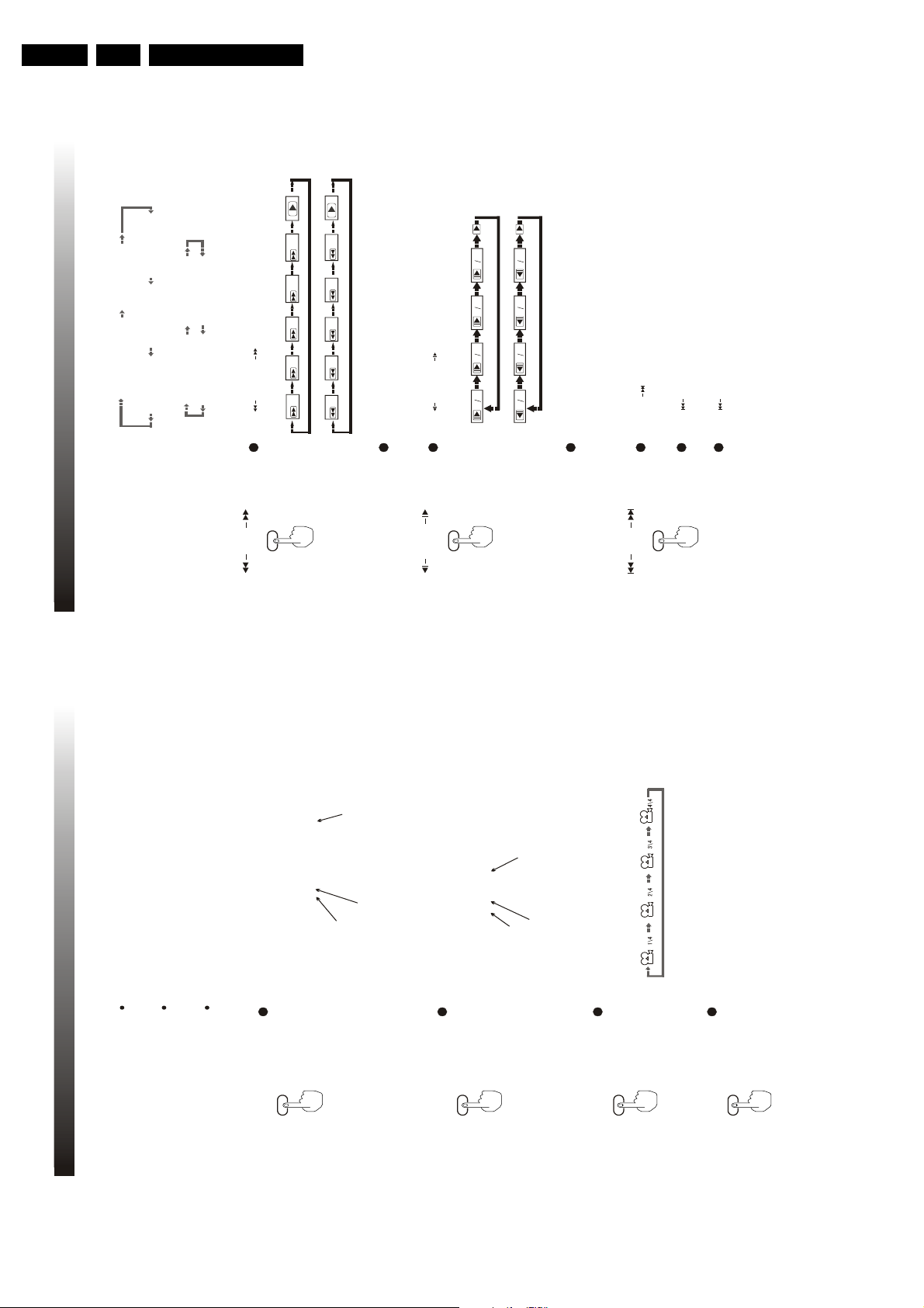
ZOOM
1
During playback, press ZOOM button to zoom in or out
the current picture to 2, 3, 4, 1/2, 1/3, 1/4 and 1 time of
the original size sequentially and circularly
When the picture is large than the TV screen can display,
you can use CURSOR buttons to move the picture
Press ZOOM repeatedly until the original picture size is
resumed
During playback, press PLAY/PAUSE button on the remote control
to pause playback A still picture of the pause point will appear on
the TV screen
When playback paused, press PLAY/PAUSE button again to
resume playback from the pause point
During playback, press STOP button once and the player will be
in PRESTOP mode (memory stop), then press PLAY/PAUSE
button to resume playback from the stop point
Press STOP button twice and the player will be in STOP mode,
then press PLAY/PAUSE button to start playback from the
beginning of the disc
Notes This function is only available for DVD and VCD (in sequential playback mode)
nitial setting to function setup will not be available in PRESTOP mode
STOP
PLAY/PAUSE
37
13. BASIC OPERATION
EN 21TC4.1U AA 3.
13. BASIC OPERATION
Press R/L button to switch the channel mode
R/L
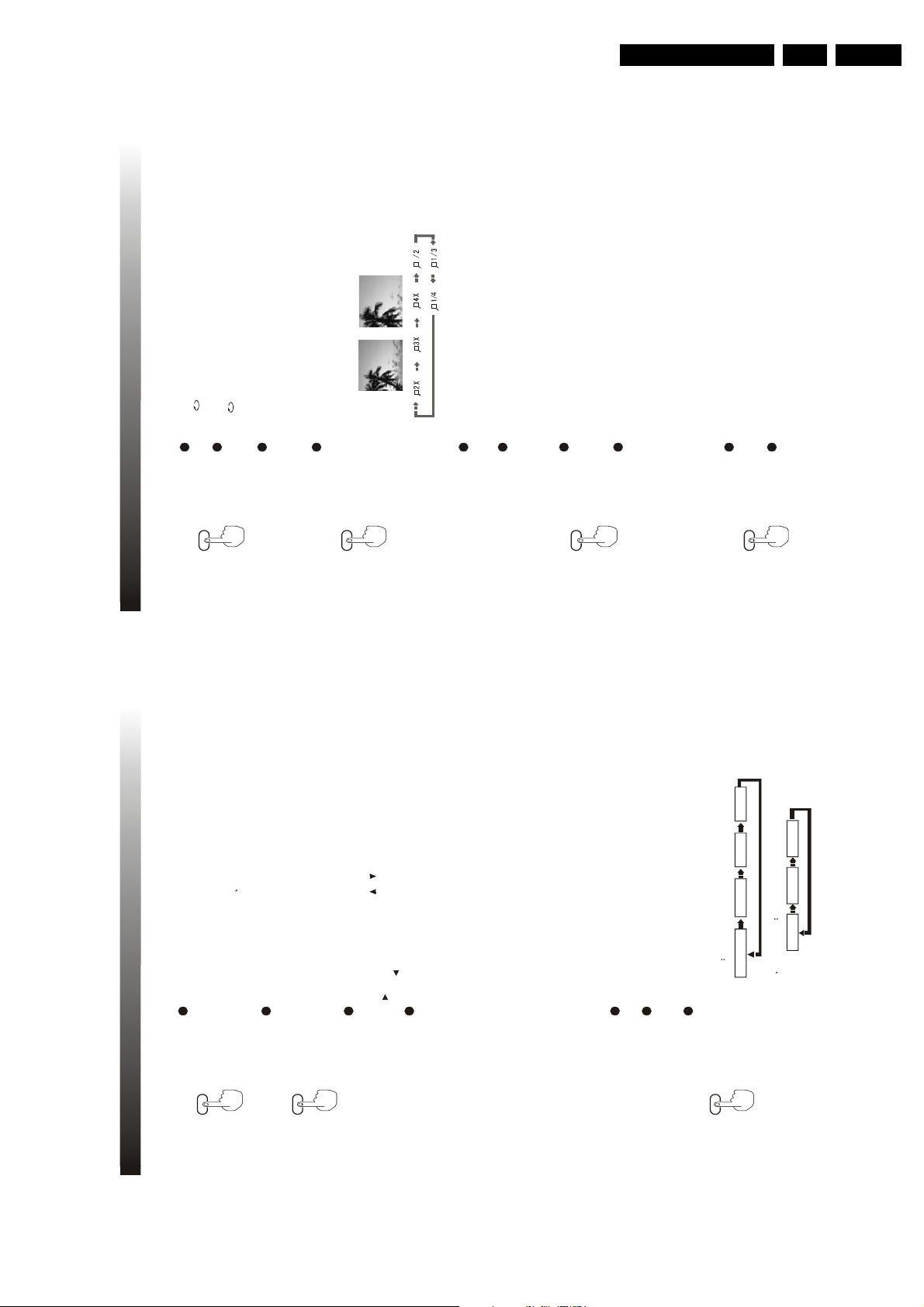
Press SEARCH MODE button once, you can see a dwindled playback
Note R/L button is for SVCD VCD and CD discs only
SEARCH
picture appear above and search information menu below f you want
to exit, repressing the button is OK and the playback picture will return
MODE
For DVD discs
to its normal size
For DVD discs and VCD ones, the search information displayed is
different We will make introduction in detail respectively
The search information includes T TLE, CHAPTER, AUD O, SUBT TLE,
ANGLE, TT T ME, CH T ME, REPEAT and T ME D SP You can select a
certain item by CURSOR or When a certain item is selected, press
to change its status or value Then press ENTER to save your setting
Press to go back to option volume
02/03
06/26
5.1 CH CHINESE
OFF
TITLE
CHAPTER
AUDIO
SUBTITLE
For example
02 is the desired title number and 03 is the total title number
06 is the desired chapter number and 26 is the total chapter number
(The exact total number of title or chapter differs depending
on the disc )
Time format HOUR M NUTE SECOND
Note For TT T ME (means title total time) and CH T ME (means chapter time),
you can input your desired value, after you finish inputting, the playback picture
For VCD discs
The search information includes TRACK, D SK T ME, TRACK T ME, REPEAT
will jump to where the time corresponds to But the displayed time remains
and T ME D SP
unchanged
Press REPEAT button to switch the repeat mode in below
Operation procedures are the same as for DVD discs
REPEAT
DVD disc
sequence
Repeat_A Repeat OffRepeat_track
T t e repeat on Repeat a Repeat off
36
Chapter repeat on
SVCD VCD discs
Notes Repeat playback is only available in PBC OFF mode for VCD2 0 and Super VCD discs
Page 22

EN 22 TC4.1U AA3.
ENTER
TV D SPLAY
The width-to-height ratio of conventional TV is 4 3, while the one of wide screen TV is 16 9
This width-to-height ratio is called the aspect ratio When viewing discs recorded in different
aspect ratio, the image's width-to-height ratio can be switched to match the TV or monitor
being used
There are three sub-items for item TV D SPLAY NORMAL/PS, NORMAL/LB and W DE Select
NORMAL/PS or NORMAL/LB according to your preference when using a conventional TV; select
W DE when using a wide screen TV
Then press cursor / to select one form For example, NORMAL/LB is selected Then press
ENTER to confirm and save the setting
You can press CURSOR to go back to the previous menu any time and follow the procedures
above to go on with other settings
Pressing SETUP at any time can clear the menu off
We make a further explanation about all the items as follows
39
-- GENERAL SETUP PAGE --
TV DISPLAY
ANGLE MARK
OSD LANG
CAPTIONS
NORMAL/PS
NORMAL/LB
WIDE
NORMAL TVLETTER BOX
LAST MEMORY
ENTER
As the above picture shows, TV D SPLAY is chosen and has three different forms Now it is
NORMAL/PS f you want to change its form to another form, you use CURSOR to see
the highlighted bar changes its color to the same with TV D SPLAYs Simultaneously, the
relevant description in the left-bottom corner will change The following picture tells that
-- GENERAL SETUP PAGE --
TV DISPLAY
ANGLE MARK
OSD LANG
CAPTIONS
NORMAL/PS
NORMAL/LB
WIDE
NORMAL TVPAN SCAN
LAST MEMORY
,
14. BASIC SETTING
Directions For Use
To achieve to the best effect of the DVD player, you may need to perform initial setting according to the
14. BASIC SETTING
content of the disc and peripheral equipment Details of all the adjustable functions will be described
later in this chapter Press SETUP to access the setup menu directly and press CURSOR / to repeat
setup page in below sequence To be noticeable, PREFERENCE SETUP page can be accessed only
when DVD is in STOP status And during playback, the cycle will be jumping from V DEO SETUP to
V deo setup
Ana og aud o setup Doby d g ta setup
Preference setup
Genera setup
GENERAL SETUP directly
GENERAL SETUP
-- GENERAL SETUP PAGE --
SETUP
ANGLE MARK
TV DISPLAY
OSD LANG
CAPTIONS
LAST MEMORY
GOTO GENERAL SETUP PAGE
and relevant description appears in left-bottom corner
option When selected, the option item is highlighted with its submenu on the right meantime
Use cursor buttons to enter the current page and press cursor / select the desired setup
NORMAL/PS
-- GENERAL SETUP PAGE --
TV DISPLAY
NORMAL/LB
WIDE
ANGLE MARK
OSD LANG
CAPTIONS
ENTER
LAST MEMORY
SET TV DISPLAY MODE
38
Page 23

Directions For Use
ANALOG AUDIO SETUP
DOWNM X
LT/RT Output mixed two-channel audio encoded with Dolby DOWNM X method, which
can be reverted back to multi-channel audio via an amplifier with Dolby Pro Logic decoder
STEREO This is a Dolby Stereo audio effect Signals of multi-channel audio are mixed into
the left and right channel, so sound from channels other than left and right can be heard
POST DRC(Dynmic Range Compression)
There are three options ON, OFF and AUTO
-- AN ALOG AU DIO SET UP PAGE --
DOWNMIX
POST DRC
GOTO ANALOG AUDIO SETUP PAGE
41
This setting is used to control sound from speaker of this set itself
14. BASIC SETTING
-- AN ALOG AU DIO SET UP PAGE --
DOWNMIX
GOTO ANALOG AUDIO SETUP PAGE
ON
OFF
AUTO
POST DRC
EN 23TC4.1U AA 3.
Viewing discs recorded in 16:9 aspect ratio on a standard 4:3 TV
14. BASIC SETTING
The Letter Box presentation
places black bars at the top and
bottom portions of the screen to
provide the full wide screen pre-
sentation of a movieon a stan-
Set to NORMAL/LB
dard TV (4:3 aspect ratio)
Wide screen format DVD /
Super VCD
Setting and Appearance
Wide screen format DVD
DVD/Super VCD screen size format
Set to NORMAL/PS
The Pan & Scan presentation
crops both sides of the wide sc-
reen presentation to use the full
standard TV screen.
Set to WIDE
Wide screen format DVD / Super
VCD (unnatural squeezed effect)
When viewing a wide screen
format DVD or Super VCD on a
standard TV and TV DISPLAY is
set to WIDE, the picture may
appear 'squeezed' on the screen.
To remedy this condition, select
either NOREMAL/LB or NOR-
MAL/PS.
Note
Whether the aspect can be switched or not depends on the disc
ANGLE MARK
Some discs may not include the screen format selected in the TV D SPLAY setting n this case,
the standard TV screen format available on the disc is automatically selected
ON angle mark will appear in top-right corner of the TV screen
OFF angle mark will be invisible
ANGLE MARK
Note this function is only available for DVD discs that have scenes
recorded from multiple angles
On-Screen Display Language consists of ENGL SH, FRENCH and SPAN SH When selected,
all on-screen display information for SETUP MENU and remote control operation will be in the
relevant language
OSD LANG
CAPT ONS
ON CAPT ONS will view on-screen closed caption
OFF CAPT ONS will be invisible
LAST MEMORY
ON When you change the set status from DVD to TV and back to DVD again, the DVD playback
Note This function is only available for certain DVD discs
40
will remain where it was before you did the change
OFF Turn off the last memory function
Page 24
EN 24 TC4.1U AA3.
P CTURE PREV EW
While a picture being played, press STOP button to access the preview screen Use CURSOR
( )buttons to select the preferred picture and press ENTER to play
KODAK P CTURE CD PLAYBACK
Kodak Picture CD looks exactly the same as a common Compact Disk t can be ordered in a
Kodak color photograph shop with "Kodak Picture CD" logo when developing and printing
135mm color film or APS (Advanced Photograph System) film The shop will develop and
print your film and store all your photos in a compact disk This Kodak Picture CD can be slide
shown with the DVD player
Each picture will be adjusted pro rata to fit the TV screen All
pictures can be zoomed, rotated and
changed slide-showing style as stated above
Kodak Picture CD mark
Notes in preview mode, you can also select "slide show" or view the menu descriptioin
47
15. MP3/PICTURE CD PLAYBACK
Directions For Use
15. MP3/PICTURE CD PLAYBACK
REPEAT FOLDER
Repeat all the tracks inside the selected folder
REPEAT ONE
Repeat only the selected track inside the selected folder
RANDOM
Play tracks inside the selected folder
JPEG P CTURE PLAYBACK
MP3/PICTURE CD Playback
Same as MP3 CD, JPEG picture play modes also include FOLDER, SHUFFLE, REPEAT
FOLDER and REPEAT ONE
Some MP3 CD and other discs also contain JPEG picture files, which can be viewed with
the DVD player
Basic operation for Picture CD playback
ZOOM
While a picture being displayed, press ZOOM and "ZOOM 100%" will appear on screen,
and then you can press F F button to enlarge the picture up to 200% and FR button to
make it smaller up to 50%
Notes When a picture is enlarged, use CURSOR ( )buttons to move the picture While
moving, in top-left corner of the screen will respectively appear PAN LEFT, PAN R GHT,
ROTAT NG
While a picture being displayed, press CURSOR( )buttons to rotate the picture
PAN UP, PAN DOWN, which will remain for about 3 seconds
LEFT and R GHT buttons each pressing rotate picture by 90, press four times to resume the
original position
UP button each pressing flip the picture horizontally, press twice to resume the original
position
DOWN button each pressing flip the picture vertically, press twice to resume the original
position
46
Page 25

Directions For Use
Above disc type mark can be found on disc labels or disc jackets
CDR and CDRW discs recorded in CD Audio or Video CD format, or with MP3 audio files, are
also playable
CAUTION
CDR/CDRW discs recorded using a personal computer or a CD recorder may not play if the
disc is damaged or dirty, or if there is dirt or condensation on the player's lens
f you record a disc using a personal computer, even if it is recorded in a compatible format,
there are cases in which it may not play because of the settings of the application software
used to create the disc (Check with the software publisher for more detailed information )
49
16. SPECIFICATION
EN 25TC4.1U AA 3.
16. SPECIFICATION
Color system : PAL/MUL T /NTSC
working humidity : 10% ~ 80%
DVD horizontal resolution : 500 line
working temperature : 0 ~ 40C
Environment:
SVCD horizontal resolution : 350 line
Video:
VCD horizontal resolution : 250 line
Signal to noise : 95 dB
+
Frequency response : 20 Hz ~ 20 KHz 1 dB
Distortion and noise : -70dB
Dynamic range : > 80dB
Audio:
Crosstalk : 80dB
Disc features and
Diameter /
Playable discs
playback time
Playable sides
types and marks
Digital audio, digital video
DVD video
DVD video
135 min.
MPEG2, moving pictures + sound
12cm single-sided 1 layer
270 min.
2 layer
270 min.
12cm double-sided 1 layer
540 min.
2 layer
Digital audio, digital video
DVD video
MPEG2, moving pictures + sound
45 min.
8cm single-sided 1 layer
70 min.
2 layer
83 min.
8cm double-sided 1 layer
152 min.
2 layer
Digital audio, digital video, MPEG2
1/2,2/3, moving pictures + sound
Super VCD
Super VCD
40 min.
10 min.
Digital audio, digital video,
12cm single-sided
8cm single-sided
74 min.
20 min.
MPEG1, moving pictures + sound
12cm single-sided
8cm single-sidedCD12cm single-sided
VCD
VCD
Compressed digital audio
CD
74 min.
20 min.
8cm single-sided
Compressed digital audio
Up to 170 songs, 12 hr.
12cm single-sided
MP3 discs
MP3
48
Page 26

EN 26 TC4.1U AA3.
Problem
Playback is not
possible
No picture
Distorted picture or
black-and-white picture
No sound
Picture quality is poor
Possible cause
The disc is above the Parental Lock Level.
The video cable is not connected properly.
The audio cable is not connected properly
Output color system (NTSC/PAL) does
not match the TV color system.
The disc is not compatible or seriously
damaged.
The disc is loaded upside down.
Condensation inside the player.
The TV is not set up properly.
The disc is not clean or scratched.
MUTE is on.
Audio is set to digital output
Solution
Press SYSTEM button to switch to the
appropriate color system.
Only use playable discs.
Make sure the label side is facing up.
Turn off the Parental Control.
Turn on the player to warm up for about
30 min.
Connect the video cable properly.
Set the TV input to AV, S-video or Com-
ponent Video and press VIDEO button on
remote control to match the video output
of the player.
Clean the disc or replace the disc.
Connect the audio cable properly.
Press the MUTE button again.
Reset the audio output or use SMART
KEY function.
51
18. TROUBLESHOOTING
Directions For Use
Handling disc
Holding the disc by the edges so the surface will not be soiled with finger prints ( A)
Do not scratch the disc Do not write on the label side with a pen
Be careful not to drop or bend the disc
Do not install more than 1 disc on the disc tray
Do not try to close the disc tray when the disc is not installed in the tray properly (B )
Be sure to store the disc in a disc case after playback
17. DISC MAINTENANCE
f the surface of the disc is soiled, wipe the disc outwards from the center with a soft,
Keep the disc away from direct sunlight, heat sources, humid or dusty areas
Cleaning disc
damp( water only) cloth ( C)
( f wipe the discs in a circular motion, circular scratches are likely to occur, which will
cause noise )
Do not use any type of solvent such as thinner, benzine, commercially available
cleaners or antistatic spray
f the disc is brought from a cold to a warm environment, moisture may form on the disc
Wipe this moisture off with a soft, lint-free cloth before using the disc
50
A
B
C
Page 27

Directions For Use
Abkhazian 6566
Afar 6565
Afrikaans 6570
Amharic 6577
Arabic 6582
Armenian 7289
Assamese 6583
Avestan 6569
Aymara 6589
Azerhaijani 6590
Bahasa Melayu 7783
Bashkir 6665
Belarusian 6669
Bengali 6678
Bihari 6672
Bislama 6673
Norwegian 7866
Bosanski 6683
Brezhoneg 6682
Bulgarian 6671
Burmese 7789
Castellano, Espanol 6983
6765
Chamorro 6772
Chechen 6769
Chewa; Chichewa; Nyanja 7889
9072
Chuang; Zhuang 9065
Church Slavic; Slavonic 6785
Chuvash 6786
Corsican 6779
Cesky 6783
Dansk 6865
Deutsch 6869
Dzongkha 6890
English 6978
Esperanto 6979
Estonian 6984
Euskara 6985
6976
Faroese 7079
7082
Frysk 7089
Fijian 7074
Gaelic; Scottish Gaelic 7168
Gallegan 7176
Georgian 7565
Gikuyu; Kikuyu 7573
Guarani 7178
Gujarati 7185
Hausa 7265
Herero 7290
Hindi 7273
Hiri Motu 7279
Hrwatski 6779
Ido 7379
Interlingua (International)7365
Interlingue 7365
Inuktitut 7385
Inupiaq 7375
Irish 7165
Italiano 7384
Ivrit 7269
Japanese 7465
Javanese 7486
Kalaallisut 7576
Kannada 7578
Kashmiri 7583
Kazakh 7575
Kernewek 7587
Khmer 7577
Kinyarwanda 8287
Kirghiz 7589
Komi 7586
Korean 7579
Kuanyama; Kwanyama 7574
Kurdish 7585
Lao 7679
Latina 7665
Latvian 7686
Letzeburgesch; 7666
Limburgan; Limburger 7673
Lingala 7678
Lithuanian 7684
Luxembourgish; 7666
Macedonian 7775
Malagasy 7771
Magyar 7285
Malayalam 7776
Maltese 7784
Manx 7186
Maori 7773
Marathi 7782
Marshallese 7772
Moldavian 7779
Mongolian 7778
Nauru 7865
Navaho; Navajo 7886
Ndebele, North 7868
Ndebele, South 7882
Ndonga 7871
Nederlands 7876
Nepali 7869
Norsk 7879
Northern Sami 8369
North Ndebele 7868
Norwegian Nynorsk; 7878
Occitan; Provencal 7967
Old Bulgarian; Old Slavonic6785
Oriya 7982
Oromo 7977
Ossetian; Ossetic 7983
Pali 8073
Panjabi 8065
Persian 7065
Polski 8076
Portugues 8084
Pushto 8083
Russian 8285
Quechua 8185
Raeto-Romance 8277
Romanian 8279
Rundi 8278
Samoan 8377
Sango 8371
Sanskrit 8365
Sardinian 8367
Serbian 8382
Shona 8378
Shqip 8381
Sindhi 8368
Sinhalese 8373
Slovensky 8373
Slovenian 8376
Somali 8379
Sotho; Southern 8384
South Ndebele 7882
Sundanese 8385
Suomi 7073
Swahili 8387
Swati 8383
Svenska 8386
Tagalog 8476
Tahitian 8489
Tajik 8471
Tamil 8465
Tatar 8484
Telugu 8469
Thai 8472
Tibetan 6679
Tigrinya 8473
Tonga (Tonga Islands) 8479
Tsonga 8483
Tswana 8478
Turkmen 8475
Twi 8487
Uighur 8571
Ukrainian 8575
Urdu 8582
Uzbek 8590
Vietnamese 8673
Volapuk 8679
Walloon 8765
Welsh 6789
Wolof 8779
Xhosa 8872
Yiddish 8973
Yoruba 8979
Zulu 9085
Bokmal,
Catalan
E
Farancais
,
7383
Islenska
20. LANGUAGE CODE
53
8482
..
,
EN 27TC4.1U AA 3.
19. REGION CODE
Region Management nformation
Region Management information This player is designed and manufactured to respond to the
Region Management nformation that is recorded on a DVD disc f the Region number described
on the DVD disc does not correspond to the region number of this year, this player cannot play
this disc
EXAMPLE
F THE Region number for this player is 1
This product incorporates copyright protection technology that is protected by
method claims of certain U S Patents and other intellectual property rights owned
by Macrovision Corporation and other rights owners Use of this copyright protection
technology must be authorized by Macrovision Corporation, and is intended for
home and other limited viewing uses only unless otherwise authorized by Macrovision
Corporation Reverse engineering or disassembly is prohibited
52
Page 28

EN 28 TC4.1U AA4.
Mechanical Instruction
4. Mechanical Instruction
4.1 Chassis Overview
DVD DE C ODER MODUL E
Figure 4-1 Chassis Overview
Page 29

4.2 Exploded Views
Mechanical Instruction
EN 29TC4.1U AA 4.
DVD DE C ODER MODUL E
Figure 4-2 Exploded Views
Page 30

EN 30 TC4.1U AA4.
Mechanical Instruction
4.3 Parts list of Exploded Views
NO. Part Name Part NO. Total
1 DVD RRONT ANEL 56-379320-1UN01 1
2 DVD SWITCH KNOB 56-379680-1HA01 1
3 SPRING KNOB 67-X24283-0E0 1
4 LENS 56-R213LE-OHC01 1
5 PCB IR RECEIVE BD 42-TD21S9-IRA 1
6 S/T SCREW B 3*8 BT 63-B30080-BT4 1
7 SPEAKER 8OHM 5W 42-50908D-BX1 2
8 S/T SCREW B3*12 AB 63-B30120-AB4 8
9 SPEAKER 16OHM 8W 42-G3516F-BX1 2
10 S/T SCREW B3*12 AB 63-B30120-AB4 4
11 FRONT CABINET 55-R213FC-2UN01 1
12 FUNCTION INLAY 58-379660-0UI01 1
13 PUSH BUTTON 56-D166FB-0UA01 1
14 S/T SCREW W3*10AB 63-W30100-AB4 2
15 CRT METAL MTG 67-325570-1E0 4
16 S/T SCREW B 4*15AB 63-B40150-AB4 20
17 S/T SCREW W 3*10AB 63-W30100-AB4 8
18 POWER INLAY 58-380690-0UI01 1
19 POWER KNOB 56-R213PK-0HA01 1
20 SPRING 67-X24970-0E0 1
21 POWER ADAPTER 62-368420-0HA 1
22 PCB SWITCH BD 42-TD21S9-SWA 1
23 S/T SCREW B 3*10AB 63-B30100-AB4 2
24 CRT BRACKET 62-396500-0UN 2
25 LENS 56-R213LE-0HC01 1
26 S/T SCREW B 3*10AB 63-B30100-AB4 2
27 HOLDER POWER CORD 62-216340-0UA 1
28 CRT A51QDX992X002(H) 44-21RFLW-SZ1A 1
29 TOOTH WASHER 6*18*2 65-A60180-20E
30 NUT M6.0*1.0 65-Z60100-50E 4
31 MAIN BD BRACKET 62-400060-1UN 4
32 P.C.B MAIN PCB BD 42-TD21S9-MAA
33 DVD SCREEN COVER
BOTTOM
34 TERMINAL BD BRACKET 62-R213TB-0UN 1
35 S/T SCREW W 3*12AB 63-W30120-AB4 2
36 INLAY REAR AV 58-R213RI-2UI 1
37 S/T SCREW B 4*15AB 63-B40150-AB4 1
38 DVD FRONT DOOR 56-379690-0UA01 1
39 DVD SCREEN COVER
UPPER
40 M/C SCREW B 3*6 64-B30060-103 4
41 S/T SCREW B 3*12 AB 63-B30120-AB4 4
42 DVD MPEG PCB 40-00TD21-DEB 2
43 M/C SCREW B 3*6 64-B30060-103 2
44 REAR CABINET 55-R213RC-1UN01 1
45 S/T SCREW B 4*20 AB 63-B40200-AB4 6
46 S/T SCREW F 3*A0 BT 63-F30100-BT3 2
67-400040-0G0 1
67-400030-0G0 1
4.4.1 Accessing the DVD Interface panel(Decoder board)
1. UUN01nscrew the four fixation screws at position (1)
shown as Figure 4-3, then separate the whole DVD
module(DVD loader and Decoder board) from the TV
chassis after you remove all cables connecting DVD
module and the TV chassis?
2. Unscrew the four fixation screws at position (2) shown as
Figure 4-4, then you can separate the Decoder board from
the DVD module after you remove all cables connecting it,
shown as Figure4-4.
4.4.2 Accessing the DVD loader
Remove the screws at position (3) shown as Figure 4-5,
remove the top-cover of the DVD loader, then you can access
the DVD loader after you remove all connection cables, shown
as Figure 4-6.
2
1
Figure 4-3 DVD Module
4.4 Service positions (DVD)
The following PWB’s or modules are added for DVD (see also
PWB location drawing, chapter 1):
1. DVD Interface panel.
2. DVD Module.
Note: Figures can deviate slightly from the actual situation, due
to different set executions.
Figure 4-4 Decoder board
Page 31

Mechanical Instruction
EN 31TC4.1U AA 4.
3
Figure 4-5 Access DVD loader
Figure 4-6
Page 32

EN 32 TC4.1U AA5.
Service Mode, Error Codes and Fault Finding
5. Service Mode, Error Codes and Fault Finding
5.1 Compair
5.1.1 Introduction
ComPair (Computer Aided Repair) is a service tool for Philips
Consumer Electronics products. ComPair is a further
development on the European DST (service remote
control),which allows faster and more accurate diagnostics.
Compare has three big advantages: .
• ComPair helps you to quickly get an understanding on how
to repair the chassis in a short time by guiding you
systematically through the repair procedures.
• ComPair allows very detailed diagnostics (on I2C level)
and is therefore capable of accurately indicating problem
areas. You do not have to know anything about I2C
commands yourself because ComPair takes care of this.
• ComPair speeds up the repair time since it can
automatically communicate with the chassis (when the
microprocessor is working) and all repair information is
directly available. When ComPair is installed together with
the SearchMan electronic manual of the defective chassis,
schematics and PWBs are only a mouse click away.
5.1.2 Specifications
ComPair consists of a Windows based faultfinding program
and an interface box between PC and the (defective) product.
The ComPair interface box is connected to the PC via a serial
or RS232 cable.
In case of the M133 chassis, the ComPair interface box and the
TV communicate via a bi-directional service cable via the
service connector.
The ComPair faultfinding program is able to determine the
problem of the defective television. ComPair can gather
diagnostic information in two ways:
• Automatic (by communication with the
television):ComPair can automatically read out the
contents of the entire error buffer. Diagnosis is done on I2C
level. Compare can access the I2C bus of the television.
ComPair can send and receive I2C commands to the micro
controller of the television. In this way, it is possible for
ComPair to ommunicate (read and write) to devices on the
I2C busses of the TV-set.
• Manually (by asking questions to you): Automatic
diagnosis is only possible if the micro controller of the
television is working correctly and only to a certain extend.
When this is not the case, ComPair will guide you through
the faultfinding tree by asking you questions (example:
Does the screen give a picture? Click on the correct
answer: YES / NO) and showing you examples (example:
Measure P202 and click on the correct oscillogram you see
on the oscilloscope). You can answer by clicking on a link
(e.g. text or a waveform picture) that will bring you to the
next step in the faultfinding process.
• By a combination of automatic diagnostics and an
interactive question / answer procedure, ComPair will
enable you to find most problems in a fast and effective
way.
• Beside fault finding, ComPair provides some additional
features like:
• Up or downloading of presets.
• Managing of preset lists.
• If both ComPair and SearchMan (Electronic Service
Manual) are installed, all the schematics and the PWBs of
the set are available by clicking on the appropriate
hyperlink.
5.1.3 How To Connect
First install the ComPair Browser software before connecting
ComPair to the M133-DVD (see the Quick Reference Card for
installation instructions). In the M133-DVD, you can only
diagnose the TV. Always start the diagnosis by connecting the
ComPair tool to the TV-set. Connection to the TV-set.
1. Connect the RS232 interface cable between a free serial
(COM) port of your PC and the PC connector (marked with
'PC') of the ComPair interface.
2. Connect the mains adapter to the supply connector
(marked with 'POWER 9V DC') on the ComPair interface.
3. Switch the ComPair interface "off".
4. Switch the television set "off" with the mains switch.
5. Connect the ComPair interface cable (3122 785 90004)
between the connector on the rear side of the Compare
interface (marked with 'I2C') and the ComPair connector
P202 on the mono carrier.
PC VCR Power I2C
Figure 5-1 ComPair set-up
1. Plug the mains adapter in the mains outlet and switch "on"
the interface. The green and red LEDs light up together.
The red LED extinguishes after approx. 1 second while the
green LED remains lit.
2. Start the ComPair program and read the 'introduction'
chapter.
Connection to the DVD-module
Follow the instructions given on the screen for further
diagnosis.
1. Use the ComPair DVD interface cable (3122 785 90017) to
connect the DVD-module to the ComPair interface.
5.1.4 How To Order
ComPair order codes:
• Starter kit ComPair32/SearchMan32 software and
ComPair interface (excl. transformer): 3122 785 90450.
• ComPair interface (excluding transformer): 4822 727
21631.
• Starter kit ComPair32 software (registration version): 3122
785 60040.
• Starter kit SearchMan32 software: 3122 785 60050.
• ComPair32 CD (update): 3122 785 60070.
• SearchMan32 CD (update): 3122 785 60080.
• ComPair interface cable for TV set: 3122 785 90004.
5.2 Error Codes
5.2.1 Error Buffer
The error code buffer contains all detected errors since the last
time the buffer was erased. The buffer is written from left to
right. When an error occurs that is not yet in the error code
buffer, it is written at the left side and all other errors shift one
position to the right.
Page 33

Service Mode, Error Codes and Fault Finding
p
EN 33TC4.1U AA 5.
5.2.2 Error Codes
In case of non-intermittent faults, clear the error buffer before
you begin the repair. These to ensure that old error codes are
no longer present.
Table 5-1 Error code overview
Error Device Error description Check item Dia-
0 Not applicable No Error
1 Not applicable X-Ray Protection(USA) C407,Q402 A2
2 - - - 3 STV9302 Vertical Protection IC301,VlotAux.±14v A2,A3
4 MSP3425G MSP I2C identification error IC1001,IC101 A5,A7
5 - - - 6 I2C bus General I2C bus error R027,R028,IC101 A5
7 - - - 8 - - - 9 M24C08 NVM I2C ident. error IC001,RO24,R025,R026 A5
10 Tuner Tuner I2C ident. error TU101,IC103 A4
11 - - - 12 - - - 13 - - 14 - - - -
If possible, check the entire contents of the error buffer. In
some situations an error code is only the result of another error
code and not the actual cause (e.g., a fault in the protection
detection circuitry can also lead to a protection).
gram
5.3 TV Fault Finding
5.3.1 No picture, no sound, no raster, fuse blown
No Picture,
No Raster,
No Sound,
Fuse Blown
Is L804(+B)
No No No
Shorted to
Earth?
Yes Yes Yes
Check the load of
+B, such as the
collector of Q402
Is the drain of
Q801 shorted
Is D801- D804
OK?
to earth?
Check IC801 and
Check Q801
Figure 5-2 No picture, no sound, no raster, and fuse blown
its peripheral
com
onents
Replace
D801-D804
Page 34

EN 34 TC4.1U AA5.
5.3.2 No picture, No sound, No Raster, and abnormal +B Voltage
Service Mode, Error Codes and Fault Finding
No Picture,
No Raster,
No sound,
Abnormal +B
Voltage
Is the +B
Yes Yes
resistance to
earth OK?
Is the working
voltage of IC803
OK?
No No
Check the load
of +B
Check VR830 and
the bias circuit of
IC803
Figure 5-3 No picture, No sound, No Raster, and abnormal +B Voltage
5.3.3 No Picture, No Sound, No Raster, and +B OK
No Picture,
Yes OK
No Raster,
No Sound,
+ B OK
Yes No No
Is the voltage
of pin17 of
IC101 9V?
No
Is the H-out
waveform at
pin13 of IC101
Replace IC101
Ok?
Check IC803 and
their peripherial
components
Check the
waveform at
static working
point of Q401
Replace Q401
and R402
Check Q402
and LOT
Is the
resistance to
Yes Yes
earth of pin17
of IC101 OK?
No No
Replace
IC101
Is the output
voltage of IC102
9V?
Check IC102
And its
Peripheral
circuits
Figure 5-4 No Picture, No Sound, No Raster, and +B OK
Check R256,
C244 and C245
Page 35

Service Mode, Error Codes and Fault Finding
OK
OK OK
No No No No
OK
No
No Picture,
No Sound,
Noise dots
Check the
AGC voltage
of the tuner
Check the VT
voltage of the
tuner
Check the voltage
of band select
terminals of the tune
r
Check the 5V power
supply terminal of the
tuner
Check the
AGC section
circuit
Check the
VT section
circuit
Check band
select section
circuit
Check 5V power
supply circuit
Check Q101 and
its peripheral
components
Check the
tuner
Replace the
tuner
OK
No
OK OK
No No No
OK
No No
Sound OK,
Raster OK,
No Picture
Check the RGB
waveform at
pin50, pin51,
pin 52 of IC101
Check Q501,
Q505,Q503 and
their peripheral
components
Check the
waveform at
p
in26 of IC101
Check the Hsync
waveform at pin62
of IC101
Check IC101 and
its peripheral
com
p
onents
Check Q203,
Q204 and their
peripheral
components
Check Q213, Q202,
Q003 and their
peripheral
components
Check the
waveform at pin30
of IC101
Check the
waveform at pin45
of IC101
Replace
IC101
5.3.4 No Picture, No Sound, Snow Dots
EN 35TC4.1U AA 5.
Figure 5-5 No Picture, No Sound, Snow Dots
5.3.5 No picture, Sound OK
Figure 5-6 No picture, Sound OK
Page 36

EN 36 TC4.1U AA5.
p
p
p
p
5.3.6 No Picture, No Raster, Sound OK
Service Mode, Error Codes and Fault Finding
No Raster,
No picture,
Sound OK
No No
Yes OK
No No
Yes OK
No
Check the
horizontal
section circuit
Check the
video amplifier
section
OK
No
OK
5.3.7 No Sound, Picture OK
Check the
heater voltage
is it 6.3V
Is the
horizontal
circuit OK?
Check the
R/G/B
cathode
Check the
screen
voltage
Replace the
CRT
Check the
voltage of pin10
of the LOT
Check R407
Replace the
CRT
Re-adjust the
Vg2 on the LOT
Figure 5-7 No Picture, No Raster, Sound OK
Replace the
LOT
Replace
R407
Picture OK,
No sound
No
OK
No No
OK OK
Check the
speakers and
OK
the leads
connected with
No
No OK No
Check the Vcc
voltage at pin13 of
IC601
Check the volume
control voltage at
in10 of IC601
Check the
waveforms
between pin 1&5
and pin 12&14 of
Check the input
signal waveforms
at pin 1&5 of
IC601
Check the peripheral
supply circuits of
pin13 of IC601
Check the waveform
at pin1 of IC101
Check the peripheral
components of pin10
of IC601
Check
IC1001
Replace
IC101
Check the
waveform at
in31 of IC101
Replace IC101
OK OK
OK No
Replace IC601
Check IC1001 and
its peripheral
com
onents
Check Q206
and its
eripheral
Replace Q206
Figure 5-8 No Sound, Picture OK
Page 37

5.3.8 No Tuning Control
p
Tuning control
does not work
Service Mode, Error Codes and Fault Finding
EN 37TC4.1U AA 5.
Is the voltage of
Yes Yes
BM terminal of
the tuner 5V?
No No
Check the 9V
power supply
circuit for the
Tuner
5.3.9 Unstorable channel
Channels
cannot be
stored
Check the Hsync
OK OK
impulse waveform
at pin62 of IC101
Varies the VT
voltage from 0 to
30V while tuning
Check the tuner
of pin SCL&SDL
Figure 5-9 No Tuning Control
Check waveform
at pin45 of IC101
with video signal
in
ut
Check the tuner
Q101, IC101 and
IF section circuit
Check Q2 13,
Q202,Q003 and
their peripheral
components
Check the IF
section and its
peripheral
circuits
OK No No
Check IC001
and IC101
Check IC101
Figure 5-10 Unstorable channel
Replace the failed
components
Page 38

EN 38 TC4.1U AA5.
5.3.10 One Horizontal Line
One horizontal line
Check the deflect yoke
junction terminal
Service Mode, Error Codes and Fault Finding
Correct it
Check the 14V
voltage at pin 4 of
IC301
Check the V sawtooth
waveform at pin 1 of
IC301
Check IC301 and
its peripheral
components
Figure 5-11 One Horizontal Line
5.3.11 No Color
No color
Check the 14V
power supply
circuit
Check IC101 and the
peripheral circuit of
pin 16 of IC101
OK No No
Check the color
system setting
Is the TV signaol
too weak?
Check the
waveform at pin
6&7 of IC101
No Yes OK
Check the peripheral
Re-setting
Check the
antenna
component of pin 47
of IC101
Figure 5-12 No Color
Check X001,
C031, C032
Page 39

Service Mode, Error Codes and Fault Finding
R125
0
SGND
5VD
*
CN1
8 PIN 2.5mm
1
2
3
4
5
6
7
8
-12V
VCC
+12V
STA/GNG /POWERON
EN 39TC4.1U AA 5.
5.4 DVD Fault Finding
5.4.1 Repair positions
1. DVD Power supply of the pins of the socket S901 on the TV
board. Refer to the TV power board maintenance section.
2. On the decoder board
2.1.Power supply: CN1
*
CN1
8
7
6
5
4
3
2
1
8 PIN 2.5mm
SGND
STA/GNG /POWERON
-12V
+12V
VCC
5VD
2.2.Crystal oscillator
0
R125
Figure 5-14 One Horizontal Line
Check whether there is 27Mhz clock signal on R41
Figure 5-13 One Horizontal Line
2.3.Audio
U12
SLRCK
SDAT0
SBCLK
VQ
RMAIN
1 14
LRCK MCLK
2
3
4
5
6
7
SDATA
BCLK
NC
CAP
AOUTR
GND
FORMAT
DEEMPH
MUTE
AOUTL
Vcc
NC
13
12
11
10
9
8
SACLK
LMAIN
+5VA
WM8726 NC
Figure 5-15 One Horizontal Line
Check if there is digital signal input on pin 1, 2, 3 and 14 and
analog audio output on pin 6 and 9 of U12.
Page 40

EN 40 TC4.1U AA5.
2.4.DVD Video signal
Service Mode, Error Codes and Fault Finding
Y4
R93
75R,1%
Y5
R100
75R,1%
Y6
R106
75R,1%
*
*
R90
NC
R112 0
1
R97
NC
R113 0
1
R104
*
NC
R114 0
1
+5VV
23
+5VV
23
+5VV
23
Q15
NC
Q18
NC
Q21
NC
C170
100p
C178
100p
C187
100p
C166
NC
L19
1.8uH 0805
C175
NC
L23
1.8uH 0805
C183
NC
L27
1.8uH 0805
C171
100p
C179
100p
C188
100p
+5VV
1 2
1 2
+5VV
1 2
1 2
+5VV
1 2
1 2
D7
1N4148
D9
1N4148
D11
1N4148
D13
1N4148
D15
1N4148
D17
1N4148
C173
NC
C181
NC
C189
NC
L20 FB 1206
L24 FB 1206
L28 FB 1206
G/Y
B/U
R/V
There are 3 video signal circuits. This Y U V video output circuit
is for your reference.
The Y U V signal of CN12A on the DVD MPEG board is to
pinP914 on the TV board .
5.4.2 Repair instruction
1. Detailed repair instructions
1.1.Troubleshooting and service of the Power Supply
Board S901 SCOKET (at DVD MODE)
1.1.1.Principle of Power Supply Operation
This appliance adopts a switched-mode power
supply,which is assembled with the TDA16846
power switch module from Philips and is capable of
protecting itself from over-current, over-voltage,
over-heat and short-circuit. The circuit mainly
stabilizes at +3.3v and fluctuate within a
permissible range, such as 5VD, VCC,+12V and 12V Please pay attention to the high voltage inside
the white silkscreen with the mark “CAUTION” on
the PCB while repairing. When using an
oscillograph to check the circuit, an isolated
transformer must be connected.
1.1.2.Troubleshooting and Service
• 5VD(S901 ‘1) , VCC(S901’3) voltage varies out
of the DVD power supply
Figure 5-16 One Horizontal Line
• Please check whether the SWITCH IC
IC901(PQ05RD21) is damage ,If IC901 is normal
Check
• whether D835 are open or short, If are not open or
short, please check whether pin59 of IC101
• have high level If have high level , check the
switching power transformer (T803) is damage.
• All the output voltages are 0V
• Check whether then IC801 is eroded, If TV working
normal, the DVD power supply
• 5VD,Vcc,+12V,-12V is not 0V.
• +12V(S901’5) and 12V (S901’7) voltage are not
normal, while other voltages are normal
• Check whether D834 and D402 are open or short,
If are not open or short,?”\switching power
• transformer is damage.
1.2.Troubleshooting and service of the Decoder and
Servo Board
1.2.1.Troubleshooting and service of the pickup
unit
• Spindle motor does not move
• Check the FFC connection between 24P of the
CN2 and the loader.
• Check if +5V voltage is normal.
• Check if laser voltage (2V for VCD and 2.2V for
DVD) exists on C pole of Q4 and Q5, if voltage on
Page 41

Service Mode, Error Codes and Fault Finding
EN 41TC4.1U AA 5.
pin 52 of U3 varies between 0 and 5V (5V for VCD
and 0V for DVD) , and if peripheral components
are eroded or badly soldered.
• If the above are all normal but there is no laser
emission, then change the loader.
• If no voltage variance on pin 52 of U3, then change
U3.
• If the pickup unit does not emit laser or focus, the
spindle motor will not move. For the non-focus
defect, check if there is signal sent from pin 12 and
pin 13 of U5to pin 1 and pin 26 of U4, and if there
are F+, F-, T+ and T- signals output from U4.
• Disc cannot be read.
• Check the FFC connection between 24P of the
CN2 and the loader.
• Check if laser voltage (2V for VCD and 2.2V for
DVD) exists on C pole of Q4 and Q5 and if they are
normal, if voltage on pin 52 of U3 varies between 0
and 5V (5V for VCD and 0V for DVD), and if
peripheral components are eroded or badly
soldered.
• Check if U3, U4, U5 and peripheral components
are eroded or badly soldered.
• Check if there is pin 8 of CN2 has RFO signal. The
normal RFO signal is a clear reticulated wave. If
not, check if bad solder exist on U3 and peripheral
components; if yes, then check the connection
between U4 and U3.
• If all the above are normal, then change U3 or the
loader.
• Only DVD disc, or only disc except DVD can be
recognized.
• Check the FFC connection between 24P of the
CN2 and the loader.
• Check if laser voltage 2V output on C pole of Q4, if
pin 125 of U3 is at low level.
• Check if pin 1 to pin 38 of U3 and the peripheral
components are badly soldered, defected and
eroded.
• Check if voltage variance exists on pin 52 of U3.
• If all the above are normal, then change U3 or the
loader.
• No video picture, normal sound
• Check if the Y1 to Y6 signals on Pin 164 to Pin 173
of U5 are normal and if short-circuit and bad solder
exist on the filter network where they are
connected to.
• Abnormal color of video picture
• Check if the 27MHz output signal is normal.
• Check if the 3.3V and 2.5V of the U1 and D1 power
supply voltages on the decoder board are normal,
and if the ripple factor is too high.
• Check if the video filter network circuit is normal.
• If all the above are normal, then change U5, U8 or
U7.
1.2.4.Troubleshooting and service of the audio unit
1. No sound
• Firstly, check if the power supply voltages +12V
and -12V to the operat ion amplifying IC U13 are
normal.
• Check if the B poles of muting transistors Q12 and
Q13 are at 0.7V. If yes, then check the relevant
muting circuit.
• Check whether bad solder exists on Pin 1, 2, 3 and
14 of U12 on the decoder board and whether the
signal is abnormal. Disconnect RN2 and check if
the clock signal ACLK, ABCK and ALRCK output
by U5 are normal. If yes, then change U12.
• Distorted audio and loud noise
• Firstly, check if the power supply voltages +12V
and -12V to the operat ion amplifying IC U13 are
normal.
• Check if the muting transistor Q12 and Q13 are
normal.
• Check if the muting transistor Q10 and Q11 are
normal. If they are abnormal, Q12 and Q13 may be
half-saturated.
• Check whether bad solder exists on Pin 1, 2, 3 and
14 of U12 on the decoder board and whether the
signal is abnormal. Disconnect RN2 and check if
the clock signal ACLK, ABCK and ALRCK output
by U5 are normal. If yes, then change U12.
1.2.2.Troubleshooting and service of the decoder
unit
• No video, no audio and buttons do not work.
• Check the all the power supplies to the decoder
board.
• Check if the reset circuit consisting of C5, R1 and
D2 is normal (at a high level for tens of
milliseconds, then constantly at 0V). If the circuit is
at low level constantly, then C5, D2 and R1 are
eroded.
• Check the 27MHz signal output, if there is no
signal output, then crystal oscillator Y1 and
peripheral components are defected or eroded.
• Check if R59 can output 93MHz signal, if not, then
check if short-circuit, bad solder or foreign object
exist on Audio DAC circuit U12, SDRAM, U8 and
U7.
• If the reset level is normal, then check the chipselection signal on Pin 26 of U10 and its address
and data signals.
• Check if short-circuit and bad solder exist on Pin
Y1 and Y6 of U5 to the subsequent filer circuit.
• If the peripheral components of U5 are all normal,
there is no short-circuit, bad solder and bad
connection on the PCB, then change the major
chip U5.
1.2.3.Troubleshooting and service of the video unit
• Loud noise when power on and off
• Check if the MUTE signal line to the resistor R81
and R87 on the base electrode of the muting
transistor Q12 and Q13 on the decoder board is
broken, and if Q12 and Q13 are eroded.
• Check if muting transistors Q11 and Q12 and the
peripheral components are defected.
• Remote reception is insensitive or fails.
• Check if the power supply voltage to the remote
censor is normal.
• Check if the remote control works properly.
• Use an oscillograph to check if there is output
waveform from the first pin IR of the remote sensor
after each pressing of buttons on the remote
control. If the remote control works correctly but
remote censor does not output, then the remote
censor should be changed.
1.2.5.Remote reception is insensitive or fails.
• Check if the power supply voltage to the remote
censor is normal.
• Check if the remote control works properly.
• Use an oscillograph to check if there is output
waveform from the first pin IR of the remote censor
after each pressing of buttons on the remote
control. If the remote control works correctly but
remote censor does not output, then the remote
censor should be changed.
Page 42

EN 42 TC4.1U AA5.
r
5.4.3 Repair flow charts
1. The power can not be on or off
The power can not
be on or off
Service Mode, Error Codes and Fault Finding
No
Check if the power
supply on the TV
main board is normal
Yes
Check if the S901 on the
TV board to CN1 on the
No
decoder board is in good
contact
Yes
Check if the Voltage
IC(3.3V) to U1 is broken
Yes
and if L29 on the decode
board is badly soldered
No
Check if there is 0V and
No
3.3V voltage difference
on pin 158 of U5
Repair the DVD
power supply on the
TV main board
Ensure S901 is in
good contact
Ensure the voltage
IC and L29 is in
good condition.
Change U5.
Yes
Figure 5-17 The power can not be on or off
Page 43

Service Mode, Error Codes and Fault Finding
2. No video picture, no sound (DVD)
No video picture, no
sound.
Check if all the voltage
No
from the TV power board
to CN1 of the decoder
board are normal.
Yes
Check if the reset circuit
consisting of C11, R1 and
No
D4 is normal(at a high level
for tens of milliseconds,
then constantly at 0V.
Yes
EN 43TC4.1U AA 5.
Check the loaded circuit.
Change C11, D4 and
R1.
Check if there is 27VHz
No
signal output.
Crystal oscillator Y1 and
peripheral components
are defected or eroded.
Yes
Check if the is 93MHz
signal output on R59.
No
Check if short-circuit, bad
solder or foreign object exist
on U12, U10, SDRAM, U7
and U8.
Yes
Yes No
Check if short-circuit and
bad solder exist on pin
No
Y1 and Y6 of U5 to the
subsequent filer circuit.
Yes
Reconnect the
component where there
Check U5.
is short-circuit or bad
solder.
Figure 5-18 No video picture, no sound (DVD)
Page 44

EN 44 TC4.1U AA5.
3. All output voltage of S901 on the TV main board is 0V or deviated
Service Mode, Error Codes and Fault Finding
1) +5V output voltage
on the TV main board is
0V or deviated.
Check if pin 2 of IC901 is
Yes
0V.
No
Yes
Check if the fast diode
D835 is blown.
2) +12V output voltage
on TV main board is 0V
or deviated.
Yes
Check if the L905 is
broken.
No
Yes
Check if the fast diode
D834 is blown.
Check if the pin4 of
IC901 is high level.
Change the fast diode
D835.
Change L905.
Change the fast diode D834
3) –12V output voltage on TV main
board is 0V or deviated.
Check if resistor R415 is blown or
Yes
broken
Change the resistor R415.
Yes
Chech if –14V voltage is on the pin 5
of the vertical amp IC301.
Yes
Check if –14V voltage is on the fast
No No
diode D402.
Figure 5-19 All output voltage of S901 on the TV main board is 0V or deviated
Check if the fast diode
D402 is blown or broken
Change the FBT
T402
Page 45

Block Diagrams, Waveforms, Wiring Diagram.
6. Block Diagrams, Waveforms, Wiring Diagram.
Block Diagram
EN 45TC4.1U AA 6.
E_14790_001
270704
Page 46

Electrical Diagrams and Print-Layouts
7. Electrical Diagrams and Print-Layouts
TV Main Carrier: Power Supply
A1
EN 46TC4.1U AA 7.
4 1U
E_14790_002
270704
Page 47

Electrical Diagrams and Print-Layouts
TV Main Carrier: Line deflection
A2
EN 47TC4.1U AA 7.
E_14790_003
270704
Page 48

Electrical Diagrams and Print-Layouts
TV Main Carrier: Frame Deflection
A3
EN 48TC4.1U AA 7.
E_14790_004
270704
Page 49

Electrical Diagrams and Print-Layouts
TV Main Carrier: Ture IF
A4
EN 49TC4.1U AA 7.
E_14790_005
270704
Page 50

Electrical Diagrams and Print-Layouts
TV Main Carrier: Video / Sound IF decoder and control
A5
EN 50TC4.1U AA 7.
E_14790_006
270704
Page 51

Electrical Diagrams and Print-Layouts
TV Main Carrier: Audio amplifier
A6
EN 51TC4.1U AA 7.
E_14790_007
270704
Page 52

Electrical Diagrams and Print-Layouts
TV Main Carrier: BTSC Sound Processor
A7
EN 52TC4.1U AA 7.
E_14790_008
270704
Page 53

Electrical Diagrams and Print-Layouts
Layout TV Main Carrier: Part1
EN 53TC4.1U AA 7.
E_14790_009a
270704
Page 54

Electrical Diagrams and Print-Layouts
Layout TV Main Carrier: Part 2
EN 54TC4.1U AA 7.
E_14790_009b
270704
Page 55

8. Alignments
Alignments
EN 55TC4.1U AA 8.
8.1 Summarization
This chassis face with South and North America N system
market “Super Single Chassis” which applied “Toshiba Combo”
IC TMPA8823 that based on Toshiba corporation MCU and
entirely small signal disposing, while the software designed
and exploited by PHILIPS design center.
Any participant to adjust this set should be familiar with the
alignment procedure instruction and the set function feature in
order to dispose questions appear in producing process.
Different from other chassis, it face with N system market, so
added BTSC/SAP ,CCD and V-CHIP function. Please pay
special attention about these functions when aligning or
inspecting
Two operation modes: User mode and factory mode, the user
mode set for user which could be operated by remote control
or key board on the top panel while the factory mode set for
producing alignment or service guiding which could only be
operated by remote control
Methods for entering into factory mode:
1. In TV mode, press the “PLAY/PAUSE” button of the remote
control to enter into factory mode.
2. Press“1,2,3,4,5,6,7,8,9,0,SCAN_DOWN,SCAN_UP,SKIP_D
OWN,SKIP_UP,SLOW_DOWN,SLOW_UP,R/
L,SEARCH,LANGUAGE,ANGLE,SUBTITLE,ZOOM,
REPEAT” keys on the remote control to switch in aligning
menu “FAC01~FAC23” in sequence ;Another method,
Press “ENTER”button firstly and then press “CH+ ,CH-
” to switch in different menu fastly.
3. Press “CH+,CH-”to select any parameter item you
want.While press “
” “ ” to change parameter value.
4. Press“PLAY/PAUSE”button again or press “MENU” button
of the remote control to quit and then the changed factory
parameter will be remembered automatically.
8.2 SPECIAL MODES
time continuously within 15 seconds .Then will enter into
factory mode.
8.3 ALIGNMENT PROCEDURE
8.3.1 FLOWCHART OF ALIGNMENT PROCEDURE
B+ Voltage
adjustment
8.3.2 Adjustment of B+ voltage
1. Apply 120VAC((±
2. Adjust VR821 in STANDARD mode until voltage at
8.3.3 RF AGC adjustment
Observe monitor the collector waveform of Q101 with the probe
of Oscilloscope as Figure 8-1. Select channel 2 (>70dB) from
the antenna input. Enter D-mode, select menu 9 to adjust
RFAGC item until the monitor peak value to 0.8V
3Pf
INPUT
RF
AGC
BTSC/SAP
CCD/V-CHIP
Screen & Focus
adjustment
Picture.geometric
adjustment
Figure 8-1
5V) to mains power input, and Philips
standard testing pattern to RF input.
C406+(B+) is 112V ±
0.5V.
IN60
White balance
adjustment
Sub- brightness
adjustment
.
p-p
OUTPUT
8.2.1 Aging mode
Used for aging before adjusting the set. Set the Bit6 of OPTM2
in D-mode as 1 when pre-setting EEPROM. Then the aging
mode and the easy button “PLAY/PAUSE” of the remote
control are in effect . When over the aligning and the factory
mode is ok ,the two items turn off automatically. Now the Bit6
set as 0 automatically.
8.2.2 Vertical stop-vibration mode
Used for confirming the speedup pole-voltage. In factory mode,
press “TV/AV/DVD" button of the remote control to enter into
vertical stop-vibration mode .Then press once more to quit
8.2.3 White balance mode
Used for white balance auto- aligning. In factory mode, Press
the“REPEAT A-B” button of the remote
control to enter into white balance mode
8.2.4 Factory OK mode
Used for initializing the user menu before sending out of
factory. Please sure there is no other operation after this.In
factory mode ,Press “MTS” button of the remote control to
enter,and then the screen will display WAIT.After finishing
initializing, it will display OK and quit automatically.If press the
“PLAY/PAUSE” button again, it can not enter into factory mode.
If you want to enter again.please follow this:,press the “volume”
button on the front panel to decrease the volume till zero ,and
simultaneously press the “0”button of the remote control three
5ΚΩ
Figure 8-2
8.3.4 Screen & Focus voltage adjustment
1. Apply pattern signal in normal status, enter D-mode, press
“TV/AV/DVD” button to turn off the vertical output.
2. Adjust the SCRREEN switch on the flyback transformer to
make a horizontal shining line just visible on the screen.
(Note: RC/GC/BC setting value is 80, GD/BD setting value
is 40)
3. Press the“TV/AV/DVD” button again to turn on the vertical
output, adjust the “FOCUS” on the flyback transformer to
obtain the optimum focus.
8.3.5 White balance adjustment
1. Apply the black and white pattern in normal status;
2. Alignment of normal color temperature
- Change Color Temperature to normal status, Press “1”of
the remote control to enter menu 1 .
- Use a color analyzer to measure the black side of the
screen. By changing the value of RCUT,GCUT and BCUT,
set the reading of the color analyzer to X=285±12,
Y=295±12.
- Use a color analyzer to measure the white side of the
screen. By changing the value of BDRV?GDRV, set the
reading of the color analyzer to X=285±12, Y=295±12.
Page 56

EN 56 TC4.1U AA8.
Alignments
- Separately set the brightness and contrast from min. to
max., repeat the step 2 and 3 until the reading of the color
analyzer is correct.
3. Alignment of warm color temperature
- Change Color Temperature to warm status, Press “2”of the
remote control to enter menu 2.
- Use a color analyzer to measure the black side of the
screen. By changing the value of RCUT -W, GCUT -W and
BCUT -W, set the reading of the color analyzer to
X=313±12, Y=323±12.
- Use a color analyzer to measure the white side of the
screen. By changing the value of BDRV -W, GDRV -W set
the reading of the color analyzer to X=313±12, Y=323±12.
- Separately set the brightness and contrast from min. to
max., repeat the step 2 and 3 until the reading of the color
analyzer is correct.
4. Alignment of cold color temperature
- Change Color Temperature to cold status, Press “3”of the
remote control to enter menu 3 .
- Use a color analyzer to measure the black side of the
screen. By changing the value of RCUT -C, GCUT -C and
BCUT -C, set the reading of the color analyzer to
X=270±12, Y=275±12.
- Use a color analyzer to measure the white side of the
screen. By changing the value of BDRV -C, GDRV -C, set
the reading of the color analyzer to X=270±12, Y=275±12.
- Separately set the brightness and contrast from min. to
max., repeat the step 2 and 3 until the reading of the color
analyzer is correct
Note: Provided the production line is equipped with the selfWhite balance adjusting equipment, white balance of M133
chassis can be adjusted automatically as following: Press
“REPEAT A-B” button under factory mode, the TV set will
adjust automatically.
8.3.6 Adjustment of Sub-brightness
1. Apply the Grey-scale/Color bar (NTSC signal) to the AV
input, in normal status.
2. Select BRTC to adjust the sub-brightness, until that the 2nd
dark bar of 8 level Grey scale just can be seen.
Note: If customers have special technics requirement about
item 5 and 6 ,Please follow customer’s adjustment standard.
8.3.7 Picture geometric distortion adjustment
Apply Philips standard testing pattern
Menu 4
HPOS5/6(horizontal center) HIGH5/6(vertical amplitude)
VP50/60(vertical center)VLIN5/6(vertical linearity)
VSC5/6(V-S Correction)
HPOS5/5(horizontal center) HIGH5/5(vertical amplitude)
VP50/60(vertical center)VLIN5/5(vertical linearity)
VSC5/5(V-S Correction)
8.3.8 BTSC/SAP Checking
BTSC/SAP function is used to check whether the demodulation
function is normal and not need to adjust.
8.3.9 CCD and V-CHIP Checking
V-CHIP function checking please refer to the operation manual.
CCD function checking see the following detailed checking
methods.
8.3.10 Initialization
Press “MTS” button of the remote control under factory mode
to initialize, the screen will display “WAIT” until “OK” appears
which means the initialization is finished. After initialization, the
set will quit factory mode automatically.
8.4 FACTORY MODE SETTING
D-mode:
Enter D-Mode by pressing“ PLAY/PAUSE” key, and then you
can enter the factory mode. Factory items are grouped into
sixteen different menus. The following tables list the groupings
of the factory items:
Table 8-1 Remote key: “1”
Factory menu 1
Item Remark Max value Default
RC R cut-off setting(for normal color temperature) FFH 80H
GC G cut-off setting (for normal color temperature) FFH 80H
BC B cut-off setting (for normal color temperature) FFH 80H
GD G drive setting (for normal color temperature) 7FH 40H
BD B drive setting (for normal color temperature) 7FH 40H
Table 8-2 Remote key: “1”
Factory menu 2
Item Remark Max value Default
RC-C R cut-off setting (for cool color temperature) FFH 80H
GC-C G cut-off setting (for cool color temperature) FFH 80H
BC-C B cut-off setting (for cool color temperature) FFH 80H
GD-C G drive setting (for cool color temperature) 7FH 40H
BD-C B drive setting (for cool color temperature) 7FH 40H
Table 8-3 Remote key: “1”
Factory menu 3
Item Remark Max value Default
RC-W R cut-off setting (for warm color temperature) FFH 80H
GC-W G cut-off setting (for warm color temperature) FFH 80H
BC-W B cut-off setting (for warm color temperature) FFH 80H
Page 57

Alignments
Factory menu 3
GD-W G drive setting (for warm color temperature) 7FH 40H
BD-W B drive setting (for warm color temperature) 7FH 40H
Table 8-4 Remote key: “4”
Factory menu 4 (for 50Hz source)
Item Remark Max value Default
HIGH5 Height (50Hz) 3FH 00H
VP50 Vertical position (50Hz) 07H 02H
VLIN5 Vertical linearity (50Hz) 0FH 0BH
VSC5 Vertical S correction (50Hz) 0FH 07H
VBLK5 Vertical blanking start & stop [1C, bit 3 ~ 0] 0FH 00H
VCEN5 Vertical center (50Hz & 60Hz) 3FH 1BH
HPOS5 Horizontal position (50Hz) 1FH 0EH
Table 8-5 Remote key: “4”
Factory menu 4 (for 60Hz source)
Item Remark ** Max value Default
HIGH6 Height (60Hz) 3FH 00H
VP60 Vertical position (60Hz) 07H 00H
VLIN6 Vertical Linearity (60Hz) 0FH 08H
VSC6 Vertical S correction(60Hz) 0FH 07H
VBLK6 Vertical blanking start & stop [1CH, bit 3 ~ 0] 0FH 00H
VCEN6 Vertical Center (50Hz & 60Hz) 3FH 1BH
HPOS6 Horizontal position (60Hz) 1FH 16H
EN 57TC4.1U AA 8.
Table 8-6 Remote key: “5”
Factory menu 5
Item Remark ## Max value Default
CNTX Maximum contrast 7FH 7FH
CNTN Minimum contrast 7FH 10H
BRTX Maximum brightness 7FH 20H
BRTN Minimum brightness 7FH 20H
COLX Maximum color 7FH 7FH
COLN Minimum color 7FH 00H
TNTX Maximum tint level 7FH 7FH
TNTN Minimum tint level 7FH 7FH
Table 8-7 Remote key: “6”
Factory menu 6
Item Remark ## Max value Default
BRTC 50% brightness 7FH 45H
COLC 50% color 7FH 50H
COLP PAL system COLC correction 7FH 00H
COLS SECAM 50% color correction 7F 00H
SCOL UV gain [06H, bit 6 ~ 4] 07H 07H
SCNT Sub-contrast [06H, bit 3 ~ 0] 0FH 0CH
CNTC 50% contrast 7FH 4CH
TNTCT 50% tint level (TV mode) 7FH 40H
TNTCV 50% tint level (AV mode) 7FH 40H
Table 8-8 Remote key: “7”
Factory menu 7
Item Remark Max value Default
ST3 50% Sharpness (TV mode, 3.58 system) 3FH 20H
ST4 50% Sharpness (TV mode, 4.43 system) 3FH 20H
SV3 50% Sharpness (AV mode, 3.58 system) 3FH 20H
SV4 50% Sharpness (AV mode, other system) 3FH 19H
SVD 50% Sharpness (DVD mode) 3FH 19H
ASSH Asymmetric sharpness [04H, bit 7 ~ 5] 07H 07H
Page 58

EN 58 TC4.1U AA8.
Factory menu 7
SHPX Maximum sharpness 3FH 1AH
SHPN Minimum sharpness 3FH 1AH
Table 8-9 Remote key: “8”
Factory menu 8
Item Remark Max value Default
MODE1
MOD2
MOD3
OPT
OPTM1
Alignments
Bit 0,Bit 1 CATV selection:00:STD 01:IRC 10:HRC 11:STD
Bit 2
Bit 3 =1: Skip A3(97)?A4(96)?A5(95)Channel
Bit 4 Super reception (PIC BOOST), 1:YES 0:NO
Bit 5 1: CCD (YES) 0: CCD(NO)
Bit 6 1:V-CHIP(YES) 0: V-CHIP (NO)
Bit 7 1: AV(YES)
Bit 0 Speed of searching
Bit 1 Speed of searching
Bit 2 =1: TV has color system PALM
Bit 3 =1: TV has color system PALN
Bit 4 =1: TV has color system NTSC358
Bit 5 =1: TV has color system PAL443
Bit 6 =1: TV has color system NTSC443
Bit 7 =1: TV has color system SECAM
Bit 0 0:woofer 1:dbe
Bit 1 0:no woofer and DBE 1:has woofer or DBE
Bit 2 =1: Has equalizer
Bit 3 =0:V-CHIP(YES), =1 V-CHIP(NO)
Bit 4 =1: has volume item in TV MENU
Bit 5 TV AVL =1: on; =0: off
Bit 6 AV AVL =1: on; =0: off
Bit 7 MONO+SAP mode 0:no 1:yes (only for BTSC)
Bit 0
Bit 1
Bit 2
Bit 3
Bit 4
Bit 5 1:TINT reverse using
Bit 6 1: NTSC system apply different APC value
Bit 7
Bit 0Bit 1
Bit 2 1: AV audio out mute when volume is zero or mute
Bit 3 =1: contrast changing when menu on
Bit4 =1: OSD don't disappear automatically
Bit5
Bit6
Bit 7
STD/IRC/HRC selection(CATV mode) 1:user control
0:under factory mode
Blue background off and TV mode no signal,0:MUTE 1:NO MUTE
Blue background off and TV mode no signal,0: external mute on 1: external mute off
=1: Vertical frequency output when change channel
not via the tune menu
=1: picture mute on (Switch between TV and AV or
change channel in the tune menu )
=1:AFT off while no signal,=0: AFT on while no signal
child lock off(When set turn on) 1:not auto clear0:
auto clear
00: 01:DK1, 10:DK2, 11:DK3Note: No effect in
NTSC only mode
Tuner selection:00:T 01:S 10:A 11:P(MK3)
0:Color temperature adjust mode, 1:color temperature adjustment mode2(namely, the three kind of
color temperature:cool,warm and normal, to be adjusted respectively.
FFH E0H
FFH 13H
FFH E8H
FFH 3CH
FFH 64H
Page 59

Alignments
Factory menu 8
OPTM2 Bit0 1: OFF set to eliminate brightness
Bit1 Power on mode: =0: Sthandby;=1: previous
Bit2 =1: Force power on
Bit 3 =1: HOTEL mode (ON)
Bit 4Bit 5 00: TV ON 01: AV ON 10: TV ON and Channel set-
ting on smallest channel no.(TV,CH2)
Bit 6 1: under factory mode turn off the set by the remote
or power off, then turn on or power on, the set enter
into factory mode and work in aging mode
Bit 7 =1: D-MODE
HDCNT Examined VSYNC in advance, then examine HSYNC before power-
ing off
HSTOP Off the Horizontal or external mute time setting when off set FFH FFH
Table 8-10 Remote key: “9”
Factory menu 9
Item Remark ** Max value Default
RFAGC RFAGC [12H, bit 5 ~ 0] 3FH 25H
BRTS BRTC Correction 3FH 00H
OSD OSD Horizontal position adjustment 7FH 21H
OSDF OSD Character width adjustment FFH 53H
CCD OSD CCD OSD Horizontal position adjustment 3FH 4AH
CCD OSDF CCD OSD Character width adjustment FFH 65H
TXCX OSD intensity when maximum contrast 1FH 1FH
RGCN OSD intensity when minimum contrast 1FH 16H
FFH 00H
FFH 00H
EN 59TC4.1U AA 8.
Table 8-11 Remote key: “0”
Factory menu 10
Item Remark ## Max value Default
V01 Volume 1 corresponded "volume register" value 3FH 46H
V25 Volume 25 corresponded "volume register" value 3FH 68H
V50 Volume 50 corresponded "volume register" value 3FH 74H
V100 Volume 100 corresponded "volume register" value 3FH 78H
VOLMAX Max volume under hotel mode 64H 32H
CURTCEN Center of the curtain FFH A5H
GATE Carrier-Mute setting FFH 2AH
VOL-OUT AV Output Voltage setting 7FH 73H
Table 8-12 Remote key: “SCAN_DOWN”
Factory menu 11
Item Remark ** Max value Default
=1:AV AUTO color system includingPAL/SECAM/
NTSC358/NTSC443;
Bit 0
=0:AV AUTO only include NTSC358,PAL-N,PAL-M
Bit 1 =1: AV has color system AUTO
MDOE4
MDOE5
Bit 2 =1: AV has color system PAL-M
Bit 3 =1: AV has color system PAL-N
Bit 4 =1: AV has color system NTSC358
Bit 5 =1: AV has color system PAL443
Bit 6 =1: AV has color system NTSC443
Bit 7 =1: AV has color system SECAM
Bit 0 =1: Has language English
Bit 1 =1: Has language French
Bit 2 =1: Has language Portuguese
Bit 3 =1: Has language Spanish
Bit 4 =1: Has language german
Bit5-Bit7 Not used
FFH 73H
FFH 0BH
Page 60

EN 60 TC4.1U AA8.
Factory menu 11
MDOE6
MDOE7
MDOE8
MDOE9
AV GAIN AV sound input plus 7FH 19H
Alignments
searching when press MENU button on the top pan-
Bit 0
el=1:(YES) 0:(NO)
Bit 1 =1: curtain when turn on the set
Bit 2 =1: curtain when turn off the set
Bit3-Bit7
Bit 2Bit 300,10: auto select USA or KOREA; 01:forced to USA;
Bit4-Bit7 Time setting for curtain when turn on the set: DATA * 8ms
V-MUTE TIME DURING POS CHANGING 200mS + 8mS
* DATA
when checked different sound source,audio mode =0: no
Bit 0
change =1: change
when checked different sound source, OSD =0: no change
Bit1
=1: change
11:forced to KOREA
Bit 4 FINE, 1:(YES) 0:(NO)
Bit 5 50Hz block 1:(YES) 0:(NO)
Bit 6 =1:contrast and brightness grow up slowly at power on
Sound mute mode =1: use the Fast_mute mode =0: use
Bit 7
Normal mute mode
Bit0 =1: Has v-chip USA rating
Bit1 =1: Has v-chip Canada rating
Bit2 =1: Has v-chip no rating
Bit3 =1: Has v-chip no rating
=1: search mode; =0: scan frequency table mode(for
Bit0
NTSC only!!!!!)
Bit1 0= Other menu mode, 1=Philips menu mode
Bit2 =1: has sound BG
Bit3 =1: has sound I
Bit4 =1: has sound DK
Bit 5 =1: has sound M
Bit6 =1: has sound L
Bit7 =1: has CH LOCK menu
FFH 01H
FFH CBH
FFH 0FH
FFH A2H
Table 8-13 Remote key: “SCAN_UP”
Factory menu 12
Item Remark ## Max value Default
MPB_STR Effect Strength 7FH 43H
MPB_HMC Harmonic Content 7FH 0DH
MPB_HP High Pass Corner Frequency 14H 07H
MPB_LP Low Pass Corner Frequency 14H 11H
MPB_LIM Amplitude Limit 20H 00H
SUB_FRE Subwoofer Corner Frequency 28H 28H
SUB_HP Subwoofer Complementary High Pass Filter 02H 02H
VOL_MAI Volume Loudspeaker 03H 00H
Table 8-14 Remote key: “SKIP_DOWN”
Factory menu 13
Item Remark ## Max value Default
OSD2 OSD Horizontal position adjustment (50%character) 7FH 20H
OSDF2 OSD Character width adjustment(50%character) FFH 64H
PYNX Normal H.SYNC max (For blue background ON-OFF) 3FH 28H
PYNN Normal H.SYNC min (For blue background ON-OFF) 3FH 18H
PYXS Search H.SYNC max(For searching) 3FH 20H
PYNS Search H.SYNC min( For searching) 3FH 1AH
Table 8-15 Remote key: “SKIP_UP”
Factory menu 14
Item Remark ## Max value Default
CLTM Color register setting(TV mode) FFH 29H
CLVO Color register setting(Video mode) FFH 29H
Page 61

Factory menu 14
Color register setting(S-video mode)
CLVS
ABL
DCBS
FLG0
FLG1
Bit 2 ~ 0 YDL [15H, bit 2 ~ 0] (-40ns~240ns)
Bit 4 ~ 3 NTSC matrix [03H, bit 7 ~ 6] (N1,N2,DVD)
Bit 5 C gamma [02H, bit 7] (color gamma on/off)
Bit 6 P/N ID [17H, bit 4] (PAL/NTSC killer sensit.)
Bit 7 FID [17H, bit 3] (Killer off)
Bit 1 ~ 0 ABL gain [16H, bit 5 ~ 4]
Bit 3 ~ 2 ABL start point [16H, bit 7 ~ 6]
Bit 4 WPS [00H, bit 7]
Bit 5 OSD ABCL [16H, bit 3]
Bit 1 ~ 0 Black stretch [15H, bit 4 ~ 3]
Bit 3 ~ 2 Y gamma[15H, bit 6 ~ 5]
Bit 5 ~ 4 OSD level[16H, bit 1 ~ 0]
Bit 7 Blank switch[0CH, bit 7]
Bit 0 Over modulation [13H, bit 5]
Bit 1 Aft window size [13H, bit 6]
Bit 2 Buzz reducer [13H, bit 7]
Bit 3 Audio gain switch [14H, bit 7]
Bit 4
Bit 5
Bit 6
Bit 7
Bit 0 CW SW [06H, bit 7], control PIN26,
Bit 1 Slice level [1EH, bit 6]
Bit 2 Mix gain [15H, bit 7]
Bit 3 V ramp bias [1DH, bit 4]
Bit 6~4
Bit 7 SLO f0 shift(test only)
1: VCO adjust automatically when changing
channel
RF setting, 011: 38.9MHz, 010: 45.75MHz, 100:
38.00Mh
Alignments
FFH 29H
3FH 27H
FFH 14H
FFH 83H
FFH 2CH
EN 61TC4.1U AA 8.
Table 8-16 Remote key: “SLOW_DOWN”
Factory menu 15
Item Remark ## Max value Default
HAFC
AGCC Not Applicable F2H 1CH
NOIS
ONTM V-mute timing w hen power on (01H = 16ms) FFH 08H
NSHP Decreased level of sharpness when noise reduction is on 3FH 1AH
PVLVL X-ray protection start point FFH 68H
PLMT
Table 8-17 Remote key: “SLOW_UP”
Factory menu 16
Item Remark ## Max value Default
D-COL Dynamic color setting 64H 23H
D-BRI Dynamic brightess setting 64H 28H
D-CON Dynamic contrast setting 64H 50H
D-SHP Dynamic sharpness setting 64H 3CH
Bit 1 ~ 0 AFC gain (TV mode) [1CH, bit 5 ~ 4]
Bit 3 ~ 2 AFC gain (AV mode) [1CH, bit 5 ~ 4]
Used to read the register R3 AFC gain 01 (TV
Bit 1 ~ 0
Bit 2 0: AFC gain as above 1: HAFC (TV mode)
Time setting When X-ray protection start point below PVLVL
,(01H = 8ms)
mode) [bit 5 ~ 6]when bigger than the reference
valueor AFC gain 00 (TV mode) [bit 5 ~ 6]
0FH 09H
07H 04H
FFH 50H
Table 8-18 Remote key: “R/L”
Factory menu 17
Item Remark ## Max value Default
S-COL Standard color setting 64H 23H
S-BRI Standard brightess setting 64H 26H
Page 62

EN 62 TC4.1U AA8.
Factory menu 17
S-CON Standard contrast setting 64H 3CH
S-SHP Standard sharpness setting 64H 32H
Table 8-19 SEARCH MODE”
Factory menu 18
Item Remark ## Max value Default
M-COL Mild color setting 64H 1EH
M-BRI Mild brightess setting 64H 2DH
M-CON Mild contrast setting 64H 46H
M-SHP Mild sharpness setting 64H 19H
Table 8-20 Remote key: “LANGUAGE”
Factory menu 19
Item Remark ## Max value Default
T-Hz120-BAS Theater mode, below 120Hz/ Bass 64H 5AH
T-Hz500-TRE Theater mode,center 500Hz/Treble 64H 5AH
T-Hz1K5 Theater mode,center 1.5kHz 18H 0CH
T-Hz5K Theater mode,center 5kHz 18H 0CH
T-Hz10K Theater mode,above 10kHz 18H 0CH
Table 8-21 Remote key: “ANGLE”
Factory menu 20
Item Remark ## Max valu e Default
C-Hz120-BAS Concert mode, below 120Hz/ Bass 64H 32H
C-Hz500-TRE Concert mode,center 500Hz/Treble 64H 32H
C-Hz1K5 Concert mode,center 1.5kHz 18H 0CH
C-Hz5K Concert mode,center 5kHz 18H 0CH
C-Hz10K Concert mode,above 10kHz 18H 0CH
Alignments
Table 8-22 Remote key: “SUBTITLE”
Factory menu 20
Item Remark ## Max valu e Default
C-Hz120-BAS Concert mode, below 120Hz/ Bass 64H 32H
C-Hz500-TRE Concert mode,center 500Hz/Treble 64H 32H
C-Hz1K5 Concert mode,center 1.5kHz 18H 0CH
C-Hz5K Concert mode,center 5kHz 18H 0CH
C-Hz10K Concert mode,above 10kHz 18H 0CH
Table 8-23 Remote key: “ZOOM”
Factory menu 22
Item Remark ## Max valu e Default
YUVGC YUV mode R cut-off compensation 3FH 03H
YUVBC YUV B cut-off 3FH 03H
WAIT_TIME Time for DVD power off FEH 30H
SAVE_TIME Time for DVD Last memoryNote: DVD waiting time= X
32ms
PWOERTIME Brightness and contrast reversion time while power on FFH 00
SECAM B-Y SECAM middle color 07H
SECAM R-Y SECAM middle color 07H
Table 8-24 Remote key: “REPEAT”
Factory menu 23
Item Remark## Max val ue Default
Media-COL Mild color setting 28
Media-BRI Mild color setting 2D
Media-CON Mild color setting 4B
Medila-SHP Mild color setting 37
Medila-COLOR OSD background and cursor color setting 44
FEH 30H
Page 63

Alignments
Factory menu 23
Char-COLOR OSD character color setting 67
Set On time RGB time setting when power on 80
Instruction for Tuner
This procedure require the tuner accord with the following conditions:
1. The below table must be followed
S/N Content Value Remarks
0 Address(ADB) 0XC0
1 Program divider(DB1) Channel corresponded sub-channel
value
2 Program divider(DB2)
3 Control informtion(CB) 0XCE Step Length:62.5KHz
4 Bandswitch(BB) Decided by suppler material Table 2.2
2. Tuner Setting for this procedure
Table 8-25 Band level
Tuner Select-
tion(OPTM1Bit6 and
Bit5)
Low band Mid band High band
01
00/10
11
Band level (Picture frequency)MHz
EN 63TC4.1U AA 8.
Table 8-26 Bandwith
Tuner Selecttion
(OPTM1Bit6?Bit5)
Low band Mid band High band
01 0X01 0X02 0X04
00/10 0X01(6ch 0X05) 0X02 0X08
11 0X01(6ch 0X41) 0X42 0X04
Table 8-27 Model No. accord with this procedure
Tuner selection
(OPTM1Bit6?Bit5)
01 P UV1336/AGN-2
00/10 A TEDH9
11 P(MK3) UV1336I/AGGS-3
Note:
1.The above information is just for reference. Please follow project manager's document while producing
2. While check locking function,key checking channels are those nearing every subsection frequency of the band
Volume count
Supplier
Bandswitch value Remarks
Special deal with
CH6
Special deal with
CH6 and mid-band-
width
Supplier BOM(For refer-
ence)
T/S 2000NJ-5
BOM (For reference)
The relationship of the volume variable and the Audio data(uPC1815)
Volume Range :0-100; Audio data Range :0-0x3f
CONDITION FORMULA
volume<=1 Audio data = volume ÞV01/1
volume<=25 V25>V01 Audio data = (volume-1) Þ(V25-V01)/24+V01
V25<=V01 Audio data = V01
volume<=50 V50>V25 Audio data = (volume-25) Þ(V50-V25)/25+V25
V50<=V25 Audio data = V25
volume>50 V100>V50 Audio data = (volume-50) Þ(V100-V50)/50+V50
V100<=V50 Audio data = V50
Page 64

EN 64 TC4.1U AA8.
Adjustment of White Balance.
TMP8823PSAN IC addressed 0x88(136), EEPROM IC addressed 0x01(160)(Just for white balance)
Parameter address
Item OSD Display Register Address
R CUT OFF RCUT 08 0x40(64)
G CUT OFF GCUT 09 0x41(65)
B CUT OFF BCUT 0x0A(10) 0x42(66)
G DRIVE GDRV 0x0B(11) 0x43(67)
B DRIVE BDRV 0x0C(12) 0x44(68)
R CUT OFF(COOL) RC-C 08 0x45(69)
G CUT OFF(COOL) GC-C 09 0x46(70)
B CUT OFF(COOL) BC-C 0x0A(10) 0x47(71)
G DRIVE(COOL) GD-C 0x0B(11) 0x48(72)
B DRIVE(COOL) BD-C 0x0C(12) 0x49(73)
R CUT OFF(WARM) RC-W 08 0x4A(74)
G CUT OFF(WARM) GC-W 09 0x4B(75)
B CUT OFF(WARM) BC-W 0x0A(10) 0x4C(76)
G DRIVE(WARM) GD-W 0x0B(11) 0x4D(77)
B DRIVE(WARM) BD-W 0x0C(12) 0x4E(78)
Alignments
EEPROM Stored ad-
dress
8.5 ADDITIONAL INSTRUCTION
1. Press “PLAY/PAUSE” button of remote control to enter or
quit D-MODE directly( OPTM2 Bit7=1)
2. The “PLAY/PAUSE” button recover to normal function
when finishing D-MODE,Namely OPTM2 Bit7 sets 0
automatically.If you want to enter into the D-MODE again,
press the “volume” button on the top panel to reduce the
volume till zero ,and simultaneously press the “0”button of
the remote control three times continuously within 15
seconds . and then enter into D-MODE .Press the “MENU”
button of the remote control to quit.
3. When PIN NO. input or V-CHIP,Press the “CH+
button on the top panel, simultaneously press the “”
button of the remote control, and then you can input the
new password.
4. Press “ENTER” button to select the item, when the hour
character change to purple,now you can input
directly.Press “ENTER”button to recover.
5. Press the "ENTER”button of the remote control in factory
mode unit the screen display MEUN TOP.Press “CH+
CH-
”button to switch different factory menu,Press the
“ENTER”button again will return to previous mode
Recover to initial status and make the directly enter D-MODE off.
Picture status :Sport,Personal setting is the same to Movies;Color temperature :cool;Noise Reduction: off;
User Volume:30;S.effect: Theater;Personal setting same to Theater;Surround on ?
C.Capt OFF;V-CHIP OFF;V-CHIP Initial Password: 0000,
1) TV?VIDEO system are priority to AUTO system .
2) When factory setting hasn't AUTO, the set will inspect NTSC3.58?PALM?PALN in sequence and initialize any system that exist in this set.If
factory don't set any system on this set. It will initialized AUTO as default setting
When receiving MON&STEREO, Initialized STEREO
When receiving MON&SAP, Initialized MONO
When receiving MON&STEREO&SAP, Initialized STEREO
1) When Initial mode is ANTENNA mode, initial channel : CH3(CABLE mode),CH3(ANTENNA mode),CH2(Recall CABLE Channel)
2) When mode1.2 is 1:STD(CABLE);When mode1.2 is 0, dicided by mode1.0& mode1.1
3) Prefer channel:CH1,CH2,CH3,CH4,CH5,(CABLE mode)corresponded CH2,CH3, CH4, CH5, CH6,CH7,(ANTENNA mode)
Off Time: OFF, 0:00; On Time: OFF;
When Tuner Mode is set to Antenna, set the Channel to 1;
When Tuner Mode is set to Cable, set the Channel to 2.
Besides, set Smart time off.
Initial language: ENGLISH
?”
6. Items marked with ”**” in D-MODE could be used to set
different data.In order to satisfy different customer,different
picture tube,and different order’requirememt.
7. Items marked with ”##” in D-MODE are the best value
which designed according to the technical specification
standard, performance requirement.If there is no new
changing material from design center.The D-MODE presetting value don’t need to adjust(default value).
Note:
1. Auto turn off,when turning on via timer and no operation
within 30 minutes
2. Auto turn off,If Smart Timer on and no operation within 4
hours in TV mode
3. Timer OFF is priority to Timer ON when time setting is the
same.
4. Auto turn off when TV no signal(blue background on)and
no operation within 15 minutes (Note:Under the four type of
auto turn off , If the user follow the “the last minute”
operation , the clock symbol will glitter on the top left screen
in the last minute.while not follow, The glitter will not
display.)
5. Factory OK mode
Note:
• Provided the production line is equipped with the selfadjusting equipment, The adjusted item should be based
on the result by such equipment.
• There’s difference between PAL geometric/OSD
adjustment and NTSC geometric/OSD adjustment. PAL
adjustment must be done before NTSC adjustment.
Page 65

9. Circuit Description
pply
Circuit Description
EN 65TC4.1U AA 9.
1. Introduction
2. Audio Signal Processing
3. Video Signal Processing
4. Synchronization and deflection processing circuit
5. Power Supply
6. Control
7. Abbreviations
8. IC Data Sheets
Notes:
• For a good understanding of the following circuit
descriptions, please use the block diagram' and/or the
electrical diagrams in section 'Block Diagram and Electrical
Diagram'. Where necessary, you will find a separate
drawing for clarification.
• Figures below can deviate slightly from the actual situation
due to different set executions.
9.1 Introduction
The main chip of this chassis apply TOSHIBA company Supersignal IC.Which contain MCU control,TV manage,AV
Switch,Horizantoal, Vertical etc. small signal disposing. Thus
TUNER TU101
E2PROM IC001
24C08
make the set has powerful function,High integration, fewer
Periphery parts, not need to any additional adjustment to
achieve PIF,SIF,AFC alignment status; Apply signal-crystal
structure and use the internal 640Fh VCO,Frequency division
and counter to attain strict sync. Signal and steady Vertical or
Horizontal pulse signal even sub-carrier wave resume signal of
all aeras’s color systems. Which provide the advantageous
qualifiation for designing the multi-system international TV.
Regarding sound, the chassis which apply German
MICROANS company MSP3425G chip to achieve BTSC/SAP
demodulation and all kinds of S-effect disposing,and
meanwhile via the software setting to select MSP3465G pure
s-effect IC to enhance the sound effect under the condition that
when no BTSC/SAP function.In addition, added real time clock
smart timer ,cool-warm color Temp., Calendar,simulate
biologic-clock,personal channel setting, hotel lock functions via
the software designing. Which improve the software additional
value.
DVD design which apply SANYO DV34 DVD Loader and MTK
company MTK1379C and MTK1336C decoder and servo
module. This project which is one of the world advanced DVD
design projects, read disc smoothly ,powerful compatibility,
super correct defects ability etc.
Line Output
+14V -14V
SAWF Z101
41 42
VIDEO IN CVBS
26
45
CVBS Monitor Output (AV)
Lo 1
Monitor Output (AV)
R01
Sub-power
su
Main Power supply
IC801 DA16846
SCL
58 13 16 58 13 16
MCU+Signal processing
IC101 TPMA8823
SIF
Y U V (from DVD Module)
BTSC Sound Processor
IC 1001 MSP3425G
Ro Lo
TO MCU
+5V
+9V
R50
Audio amplifier
IC601 TDA7496
+110V
+33V
+12V
+5V
+24V
+12V
Frame IC301
STV9302
G51
B52
Video
amplifier
L1 (AV AUDIO)
R1
L2 (DVD AUDIO)
R2
DVD module
SANYO DVD Loader
MTK1379C
MTK1366C
(TO TV CHASSIS)
YUV
-12V
Coaxial Output
9.2 Audio Signal Processing
Stereo
In stereo sets, the signal goes via the SAW filter (position
Z10A), to the audio demodulator part of the UOC IC101. The
audio output on pin 31 goes to the stereo decoder IC1001.The
Figure 9-1 Block Diagram
switch inside this IC selects either the internal decoder or an
external source (see also block diagram above).
The built-in stereo decoder item IC1001 (MSP3425G) can
receive 2CS, NICAM and BTSC stereo signals.The output is
fed ic601 to the audio amplifier (TDA7496 at position IC601).
The volume level is controlled at this IC (pin 10 ) by a 'Mute'
Page 66

EN 66 TC4.1U AA9.
Circuit Description
control line from the microprocessor. The audio signal from
IC601 is then send to the speaker and headphone output
panel.
9.3 Video Signal Processing
9.3.1 Introduction
The video signal-processing path consists of the following
parts:
• RF signal processing.
• Video source selection.
• Video demodulation.
• Luminance/Chrominance signal processing
• RGB amplifier
The processing circuits listed above are all integrated in the
UOC TV processor. The surrounding components are for the
adaptation of the selected application. The I2C bus is for
defining and controlling the signals.
9.3.2 RF Signal Processing
The incoming RF signal goes to the tuner (pos. TU101), where
the IF signal is developed and amplified. The IF signals then
exits the tuner from pin 11 to pass through the SAW filter (pos.
Z101). The shaped signal is then applied to the IF processor
part of the UOC (pos. IC101).
Tuner AGC (Automatic Gain Control) will reduce the tuner gain
and thus the tuner output voltage when receiving strong RF
signals. Adjust the AGC takeover point via the Service
DefaultAlignment Mode (SDAM). The tuner AGC starts working
when the video-IF input reaches a certain input level and will
adjust this level via the I2C bus. The tuner AGC signal goes to
the tuner (pin 1) via the open collector output (pin 43) of the
UOC.The IC also generates an Automatic Frequency Control
(AFC) signal that goes to the tuning system via the I2C bus, to
provide frequency correction when needed.
The demodulated composite video signal is available at pin 30
and then buffered by transistor Q203.
9.3.3 Video Source Selection
The Composite Video Blanking Signal (CVBS) from buffer
Q201 goes to the audio carrier trap filters 1200, 1201, or 1202
(depending on the system used), to remove the audio
signal.The signal then goes to pin 26 of IC 101. The internal
input switch selects the following input signals:
• Pin 26: terrestrial CVBS input
• Pin 24: external AV1 CVBS input
• Pin 19,20,21: external DVD YUV signal input
Once the signal source is selected, a chroma filter calibration is
performed. The received color burst sub-carrier frequency is
used for this. Correspondingly, the chroma band pass filter for
PAL/NTSC processing is switched on. The selected luminance
(Y) signal is supplied to the horizontal and vertical
synchronization circuit and to the luminance processing circuit.
In the luminanceprocessing block, the luminance signal goes to
the chroma trap filter. This trap is switched 'on' or 'off'
depending on the color burst detection of the chroma
cal bration circuit.
The group delay correction part can be switched between the
BG and a flat group delay characteristic. This has the
advantage that in multi-standard receivers no compromise has
to be made for the choice of the SAW filter.
and not affected by the content of the video signal. The tuner
features stable receptivity while the signal output from the
video detector features high fidelity.
PLL built-in PMPA8823 generates 45.75MHZ demodulation
reference signal for Sync detector to demodulate the video
signal, which is called ‘PLL Sync demodulation’.
9.3.5 Chrominance signal Processing
Through the external BPF(band-pass filter) to single out the
chroma signal and burst signal within the range of Fsc
+1.3MHZ from among the composite signals output from the
video detector. After being amplified by ACC, the chroma
signal is fed into the synchronous detector to be demodulated
to obtain the color difference signal.
9.3.6 Luminance channel and matrix circuit
The luminance channel of TMPA8823 has the black strech
circuit to make the ‘darkish’ ingredient of the picture turn
‘atrous’, thus improve the contrast and depth perception of the
picture . It also has the delayed definition-enhanced circirt to
enable the details of the picture more vivid. The luminance
signal(Y) is sent into the matrix circuit after being delayed for
0.6s and composed R/G/B signal combined with three colordifference signals(B-Y,R-Y,B-Y).
9.3.7 CRT Drive Circuit
Adopting the cascode to amplify voltage and current of R/G/B
signal ,the CRTdrive circuit is able to demodulate the cathode
beam current of the CRT. The R/G/B signal input into the
cascode circuit is of negative polarity.
9.4 Sync Separation and Deflection Processing
Circuit
TMPA8823 has the 32fh PLL (fh = horizontal frequency). In
accordance with the frequency and phase information carried
by composite sync signal, PLL generates scan clock signal with
32fh and horizontal drive pulse will be obtained through 32fh
countdown. Use integrating circuit to extract vertical sync
signal from the composite sync pulse to control the counter for
vertical countdown. The counter countdown the 32fh clock
signal, thus vertical frequency sync pulses under various
systems can be obtained.
TMPA8823 includes the vertical SW former(sawtooth wave
former) and control the gain and linear of SW(sawtooth wave).
Therefore, the vertical amplitude control and the linearity
correction of the scanning raster can be achieved by setting the
data with remote controller via I2C bus input.
9.3.4 Video Demodulation
The IF channel mainly ensures the sensitivity and selectivity of
the complete machine. The IF AMP integrated in TMPA8823 is
made up of the third-stage dual-differential amplifier with gain
value above 70dB, SNR of 55Db and bandwidth of 6MHZ. The
video demodulation circuit is made from the built-in PLL Sync
detector. The spectrum of the demodulation carrier is unitary
Page 67

9.5 Power Supply
Circuit Description
EN 67TC4.1U AA 9.
Figure 9-2 Figure 9-2 Internal block diagram of the driver IC (TDA16846)
9.5.1 Introduction
The supply is a Switching Mode Power Supply (SMPS). The
frequency of operation varies with the circuit load. The power
supply starts operating when a DC voltage goes from the
rectifier circuit (D810-D804) via T803, R812 to pin 14. The
operating voltage for the driver circuit is also taken from the
'hot' side of this transformer.
The switching regulator IC 801 starts switching the FET (Q801)
'on' and 'off', to control the current flow through the primary
winding of transformer T803. The energy stored in the primary
winding during the 'on' time is delivered to the secondary
windings during the 'off' time.
The 'MainSupply' line is the reference voltage for the power
supply. It is sampled by resistors R840, VR821 and R841 ,
regulator IC803 can get different output by adjusting VR821.
This regulator drives the feedback opto-coupler IC802 to set
the feedback control voltage on pin 5 of IC801.
The power supply in the set is 'on' any time AC power goes to
the set.
Derived Voltages
The voltages supplied by the secondary windings of T5520 are:
• +24V derived from pin 10 of T803 and +12V derived from
pin 16 of T803 are for the audio circuit
Page 68

EN 68 TC4.1U AA9.
• +12V derived from pin 12 of T803 ,-14V derived from pin 4
of LOT T402 and +5V derived from pin 13 of T803 are for
the DVD module
• 'MainSupply' for the horizontal output, +33V for tuning
system is the secondary output of Mainsupply
• +9V is the secondary output of +12V, +5V is derived from
+9V by regulator IC103, these two voltages are for
UOC,signal processing circuit .
Other supply voltages are provided by the LOT. It supplies
+14V and -14V for the Frame deflection circuit, +200 V source
for the video drive. The secondary voltages of the LOT are
monitored by the 'EHT information' lines. These lines are fed to
the video processor part of the UOC IC 101 on pins 2 and 27.
This circuit will shut 'off' the horizontal drive in case of
overvoltage or excessive beam current.
9.5.2 Basic IC Functionality Description
The TDA 16846 is optimized to control free running or fixed
frequency flyback converters with or without Power Factor
Correction (Current Pump). To provide low power consumption
at light loads, this device reduces the switching frequency
continuously
with load, towards an adjustable minimum (e. g. 20 kHz in
standby mode). Additionally, the start up current is very low. To
avoid switching stresses of the power devices, the power
transistor is always switched on at minimum voltage. A special
circuit is implemented to avoid jitter. The device has several
protection functions: VCC over- and undervoltage, mains
undervoltage, current limiting and 2 free usable fault
comparators. Regulation can be done by using the internal
error amplifier or an opto coupler feedback (additional input).
The output driver is ideally suited for driving a power MOSFET,
but it can also be used for a bipolar transistor. Fixed frequency
and synchronized operation are also possible.
The TDA 16846 is suited for TV-, VCR- sets and SAT receivers.
It also can be good used in PC monitors.
Start Up Behaviour (Pin 14)
When power is applied to the chip and the voltage V14 at Pin
14 (VCC) is less than the upper threshold (VON) of the Supply
Voltage Comparator (SVC), input current I14 will be less than
100 mA. The chip is not active and driver output (Pin 13) and
control output
(Pin 4) will be actively held low. When V14 exceeds the upper
SVC threshold (VON) the chip starts working and I14
increases. When V14 falls below the lower SVC threshold
(VOFF) the chip starts again at his initial condition. Figure 9-3
shows the start-up circuit and Figure9-4 shows the voltage
V14 during start up. Charging of C14 is done by resistor R2 of
the “Primary Current Simulation” (see later) and the internal
diode D1, so no additional start up resistor is needed. The
capacitor C14 delivers the supply current until the auxiliary
winding of the transformer supplies the chip with current
through the external diode D14.
Circuit Description
Figure 9-4 Startup Voltage Diagram
Primary Current Simulation PCS (Pin 2) / Current Limiting
A voltage proportional to the current of the power transistor is
generated at Pin 2 by the RC-combination R2, C2 (Figure 9-3).
The voltage at Pin 2 is forced to 1.5 V when the power
transistor is switched off and during its switch on time C2 is
charged by R2 from the rectified mains. The relation of V
the current in the power transistor (I
primary
) is
and
2
Lprimary: Primary inductance of the transformer
The voltage V
Comparator ONTC (see Figure 9-2). The other input is the
control voltage. If V
switches off (current limiting). The maximum value of the
control voltage is the internal reference voltage 5 V, so the
maximum current in the power transistor (I
The control voltage can be reduced by either the Error Amplifier
EA (current mode regulation), or by an opto coupler at Pin 5
(regulation with opto coupler isolation) or by the voltage V
Pin 11 (Fold Back Point Correction).
is applied to one input of the On Time
2
exceeds the control voltage, the driver
2
Mprimary
) is
at
11
Figure 9-3 Startup Circuit
Fold Back Point Correction PVC (Pin 11)
V11 is deviated by a voltage divider from the rectified mains
and reduces the limit of the possible current maximum in the
power transistor if the mains voltage increases. I.e. this limit is
independent of the mains (only active in free running mode).
The maximum current (IMprimary) depending on the voltage
V
at Pin 11 is
11
Off-Time Circuit OTC (Pin 1)
Figure 9-5 shows the Off-Time Circuit which determines the
load dependent frequency course. When the driver switches off
(Figure9-6) the capacitor C1 is charged by current I
(approx. 1
1
Page 69

Circuit Description
EN 69TC4.1U AA 9.
mA) until the capacitor’s voltage reaches 3.5 V. The charge
time TC1 is
For proper operation of the special internal anti jitter circuit,
TC1 should have the same value as the resonance time “TR”
of the power circuit (Figure 9-6). After charging C1 up to 3.5 V
the current source is disconnected and C1 is discharged by
resistor R1. The voltage
at Pin 1 is applied to the Off-Time Comparator (OFTC). The
V
1
other input of OFTC is the control voltage. The value of the
control voltage at the input of OFTC is limited to a minimum of
2 V (for stable frequency at very light load). The On-Time Flip
Flop (ONTF)
is set, if the output of OFTC is high 1) and the voltage V
3 falls below 25 mV (zero crossing signal is high). This ensures
switching on of the power transistor at minimum voltage. If no
zero crossing signal is coming into pin 3, the power transistor
is switched
on after an additional delay until V
Figure 9-5, OFTCD). As long as V
control voltage, ONTF is disabled to suppress wrong zero
crossings of V
transformer after switch-off. The
discharge time of C1 is a function of the control voltage.
1) i.e. V
, due to parasitic oscillations from the
3
is less than the limited control voltage.
1
falls below 1.5 V (see
1
is higher than the limited
1
at Pin
3
Figure 9-6 Pulse Diagram of Off-Time-Circuit
Figure 9-7 shows the converters switching frequency as a
function of the output power.
Control Voltage Output Power Off-time TD1
1.5 - 2 V Low Constant (TD1MAX.),
const. frequency stand
by
2 - 3.5 V Medium Decreasing
3.5 - 5 V High Free running, switch-on
If the control voltage is below 2 V (at low output power) the “offtime” is maximum and constant
TD1
.≈0.47R1xC1
MAX
at first minimum
Figure 9-7 Load Dependant Frequency Course
Error Amplifier EA / Soft-Start (Pin 3, Pin 4)
Figure 9-8 shows the simplified Error Amplifier circuit. The
positive input of the Error Amplifier (EA) is the reference
voltage 5 V. The negative input is the pulsed output voltage
from the auxiliary winding, divided by R31 and R32. The
capacitor C3 is dimensioned only for delaying zero crossings
and smoothing the first sp ke after switchoff. Smoothing of the
regulation voltage is done with the soft start capacitor C4 at Pin
4. During start up C4 is charged with a current of approx. 2 mA
(Soft Start). Figure9-9 shows the voltage diagrams of the Error
Amplifier circuit.
Figure 9-5 Off-Time-Circuit
Figure 9-8 Error Amplifier
Page 70

EN 70 TC4.1U AA9.
Circuit Description
Synchronization mode is also possible. The synchronization
frequency must be higher than the oscillator frequency.
Figure 9-9 Regulation Pulse Diagram
Fixed Frequency and Synchronization Circuit SYN (Pin 7)
Figure 9-10 shows the Fixed Frequency and Synchronization
Circuit. The circuit is disabled when Pin 7 is not connected.
With R7 and C7 at Pin 7 the circuit is working. C7 is charged
fast by approx. 1 mA and discharged slowly by R7 (Figure 9-
10). The power transistor is switched on at beginning of the
charge phase. The switching frequency is (charge time
ignored)
When the oscillator circuit is working the Fold Back Point
Correction is disabled (not necessary in fixed frequency mode).
“Switch on” is only possible when a “zero crossing” has
occurred at Pin 3, otherwise “switch-on” will be delayed (Figure
9-10).
Figure 9-12 Ext. Synchronization Circuit
9.5.3 Protection Functions
The chip has several protection functions:
Current Limiting
See “Primary Current Simulation PCS (Pin 2) / Current
Limiting” and “Fold Back Point Correction PVC (Pin 11)”.
Over- and Undervoltage Lockout OV/SVC (Pin 14)
When V14 at Pin 14 exceeds 16 V, e. g. due to a fault in the
regulation circuit, the ErrorFlip Flop ERR is set and the output
driver is shut-down. When V14 goes below the lower SVC
threshold, ERR is reset and the driver output (Pin 13) and the
soft-start (Pin 4) are
shut down and actively held low.
Primary Voltage Check PVC (Pin 11)
When the voltage V11 at Pin 11 goes below 1 V the Error Flip
Flop (ERR) is set. E.g. a voltage divider from the rectified mains
at Pin 11 prevents from high input currents at too low input
voltage.
Free Usable Fault Comparator FC1 (Pin 10)
When the voltage at Pin 10 exceeds 1 V, the Error Flip Flop
(ERR) is set. This can be used e. g. for mains overvoltage
shutdown.
Free Usable Fault Comparator FC2 (Pin 6)
When the voltage at Pin 6 exceeds 1.2 V, the Error Flip Flop
(ERR) is set. A resistor between Pin 9 (REF) and ground is
necessary to enable this fault comparator.
Voltage dependent Ringing Suppression Time
During start-up and short-circuit operation, the output voltage
of the converter is low and parasitic zero crossings are applied
for a longer time at Pin 3. Therefore the Ringing Suppression
Time TC1 (see “Off-Time Circuit OTC (Pin 1)”) is made longer
with factor 2.5 at low output voltage. To ensure start-up of the
circuit, the value of resistor R1 (Pin 1, Figure 9-5) must be
higher than 20 kW.
Figure 9-10 Synchronization and Fixed Frequency Circuit
Figure 9-11 Pulse Diagram for Fixed Frequency Circuit
Page 71

9.6 Control
Circuit Description
EN 71TC4.1U AA 9.
9.6.1 Introduction
The microprocessor part of the UOC, has the complete control
on board. User menu, Service Default Mode, Service
Alignment Mode and Customer Service Mode are generated by
the uP. Communication to other ICs is done via the I2C-bus.
9.6.2 I2C-Bus
The main control system, which consists of the microprocessor
part of the UOC (IC101), is linked to the external devices (tuner,
NVM, MSP, etc) by means of the I2C-bus. An internal I2C-bus
is used to control other signal processing functions, like video
processing, sound IF, vision IF, synchronization, etc.
9.6.3 User Interface
The M133 uses a remote control with RC5 protocol. The
incoming signal is connected to pin 63 of the UOC.
The 'Top Control' keyboard, connected to UOC pin 3, can also
control the set. Button recognition is done via a voltage divider.
The front LED (D401) is connected to an output control line of
the microprocessor (pin 56). It is activated to provide the user
information about whether or not the set is working correctly
(e.g., responding to the remote control, normal operation (USA
only) or fault condition)
9.6.4 In- and Output Selection
For the control of the input and output selections, there are
three lines:
STATUS1. In the TV mode, it outputs TV signal, including
VIDEO and AUDIO signal.
STATUS2. In the AV mode, it outputs AV signal, including
VIDEO and AUDIO signal.
STATUS3. In the DVD mode, it outputs DVD signal, including
VIDEO and AUDIO signal.
9.6.5 Power Supply Control
The microprocessor part is supplied with 5V derived from the
'MainAux' voltage via a 5V stabilizer (D817) and a diode.Two
signals are used to control the power supply:
Figure 9-13 lock diagram set control
Stdby_con. This signal is generated by the microprocessor
when over-current takes place at the 'MainAux' line. This is
done to enable the power supply into standby burst mode, and
to enable this mode during a protection. This signal is 'low'
under normal operation conditions and goes to 'high' (5V)
under 'standby' and 'fault' conditions.
POWER_DOWN. This signal is generated by the power
supply. Under normal operating conditions, this signal is 'high'
(5 V). During 'standby' mode, this signal is a pulse train of
approx. 10 Hz and a 'high' duration of 5 ms. It is used to give
information to the UOC about the fault condition in the Audio
amplifier supply circuit. This information is generated by
sensing the current on the 'MainAux' line (using voltage drop
across R249 to trigger Q207). This signal goes 'low' when the
DC-current on the 'MainAux' line exceeds 1.6 - 2.0 A. It is also
used to give an early warning to the UOC about a power failure.
Then the information is used to mute the sound amplifier to
prevent a switch off noise and to solve the switch-off spot.
9.6.6 Protection Events
Several protection events are controlled by the UOC:
BC protection, to protect the picture tube from a too high beam
current. The UOC has the capability of measuring the normal
back level current during the vertical flyback. Soif for some
reason the CRT circuit is malfunctioning (i.e. high beam
current), the normal black current will be out of the 75 A range,
and the UOC will trigger the power supply to shut down.
However, this is a high beam-current situation, the TV screen
will be bright white before the set is shut down.
I2C protection, to check whether all I2C ICs are functioning.
In case one of these protections is activated, the set will go into
'standby'.
The 'on' and 'standby' LEDs are controlled via the UOC.
9.7 Abbreviation list
2CS 2 Carrier (or Channel) Stereo
ACI Automatic Channel Installation:
algorithm that installs TV sets directly
from cable network by means of a
predefined TXT page
ADC Analogue to Digital Converter
Page 72

EN 72 TC4.1U AA9.
Circuit Description
AFC Automatic Frequency Control: control
signal used to tune to the correct
frequency
AFT Automatic Fine Tuning
AGC Automatic Gain Control: algorithm that
controls the video input of the feature
box
AM Amplitude Modulation
AP Asia Pacific
AR Aspect Ratio: 4 by 3 or 16 by 9
ATS Automatic Tuning System
AV External Audio Video
AVL Automatic Volume Level
BC-PROT Beam Current Protection
BCL Beam Current Limitation
B/G Monochrome TV system. Sound
carrier distance is 5.5 MHz
BLC-INFORMATION Black current information
BTSC Broadcast Television Standard
Committee. Multiplex FM stereo
soundsystem, originating from the
USA andused e.g. in LATAM and AP-
NTSC countries.
B-TXT Blue teletext
CBA Circuit Board Assembly
CC Closed Caption
Compare Computer aided rePair
CRT Cathode Ray Tube or picture tube
CSM Customer Service Mode
CTI Color Transient Improvement:
manipulates steepness of chroma
transients
CVBS Composite Video Blanking and
Synchron
DAC Digital to Analogue Converter
DBE Dynamic Bass Enhancement: extra
low frequency amplification
DBX Dynamic Bass Expander
D/K Monochrome TV system. Sound
carrier distance is 6.5 MHz
DFU Direction For Use: description for the
end user
DNR Dynamic Noise Reduction
DSP Digital Signal Processing
DST Dealer Service Tool: special remote
control designed for dealers to enter
e.g. service mode
DVD Digital Versatile Disc
EEPROM Electrically Erasable and
Programmable Read Only Memory
EHT Extra High Tension
EHT-INFORMATION Extra High Tension information
EU Europe
EW East West, related to horizontal
deflection of the set
EXT External (source), entering the set via
SCART or Cinch
FBL Fast Blanking: DC signal
accompanying RGB signals
FILAMENT Filament of CRT
FLASH Flash memory
FM Field Memory
FM Frequency Modulation
HA Horizontal Acquisition: horizontal sync
pulse coming out of the HIP
HFB Horizontal Flyback Pulse: horizontal
sync pulse from large signal deflection
HP Headphone
Hue Color phase control for NTSC (not the
same as 'Tint')
I Monochrome TV system. Sound
carrier distance is 6.0 MHz
I2C Integrated IC bus
IF Intermediate Frequency
IIC Integrated IC bus
Interlaced Scan mode where two fields are used
to form one frame. Each field contains
half the number of the total
amount of lines. The fields are written
in 'pairs' causing line flicker.
ITV Institutional TV
LATAM Latin America
LED Light Emitting Diode
L/L' Monochrome TV system. Sound
carrier distance is 6.5 MHz. L' is Band
I, L is all bands except for Band I
LNA Low Noise Amplifier
LS Large Screen
LS Loudspeaker
LSP Large signal panel
M/N Monochrome TV system. Sound
carrier distance is 4.5 MHz
MSP Multi standard Sound Processor: ITT
sound decoder
MUTE Mute-Line
NC Not Connected
NICAM Near Instantaneous Compounded
Audio Multiplexing. This is a digital
sound system, mainly used in Europe.
NTSC National Television Standard
Committee. Color system mainly used
in North America and Japan.
Color carrier NTSC M/N =3.579545
MHz, NTSC 4.43 = 4.433619 MHz
(this is a VCR norm, it is not
transmitted off-air)
NVM Non Volatile Memory: IC containing
TV related data e.g. alignments
OB Option Byte
OC Open Circuit
OSD On Screen Display
PAL Phase Alternating Line. Color system
mainly used in West Europe (color
carrier = 4.433619 MHz) and South
America (color carrier PAL M
=3.575612 MHz and PAL N =
3.582056 MHz)
PCB Printed Circuit board
PIP Picture In Picture
PLL Phase Locked Loop. Used for e.g.
FST tuning systems. The customer
can give directly the desired frequency
POR Power-On Reset
Progressive Scan Scan mode where all scan lines are
displayed in one frame at the same
time, creating a double vertical
resolution.
PTP Picture Tube Panel (or CRT-panel)
RAM Random Access Memory
RC Remote Control handset
RC5 Remote Control system 5, signal from
the remote control receiver
RGB Red Green Blue
ROM Read Only Memory
SAM Service Alignment Mode
SAP Second Audio Program
SC Sandcastle: pulse derived from sync
signals
S/C Short Circuit
SCAVEM Scan Velocity Modulation
SCL Serial Clock
SDA Serial Data
SDM Service Default Mode
SECAM SEequence Couleur Avec Memoire.
Color system mainly used in France
and East Europe. Color carriers
4.406250 MHz and 4.250000 MHz
SIF Sound Intermediate Frequency
SS Small Screen
STBY Standby
Page 73

Circuit Description
EN 73TC4.1U AA 9.
SVHS Super Video Home System
SW Software
THD Total Harmonic Distortion
TXT Teletext
UP Microprocessor
UOC Ultimate One Chip
VA Vertical Acquisition
VBAT Main supply voltage for the deflection
stage (mostly 141 V)
V-chip Violence Chip
VCR Video Cassette Recorder
WYSIWYR What You See Is What You Record:
record selection that follows main
picture and sound
XTAL Quartz crystal
Y Luminance (Y) and Chrominance (C)
signal
9.8 IC Pin Description
9.8.1 ST24C08
9.8.2 STV9302
Figure 9-16 Pin Connection
Figure 9-14 Block Diagram
Figure 9-15 Pin Connection
Table 9-1 Signal Names
PRE Write Protect Enable
E Chip Enable Input
SDA Serial Data Address Input/Output
SCL Serial Clock
MODE Multibyte/Page Write Mode(C version)
WC Write Control (W version)
VCC Supply Voltage
VSS Ground
Figure 9-17 Block Diagram
9.8.3 TDA16846
Figure 9-18 Pin Connection
Page 74

EN 74 TC4.1U AA9.
Circuit Description
Figure 9-19 Block Diagram
Table 9-2 Pin Definition and Functions
Pin Symbol Function Short Description of the Pin Functions
1 OTC Off Time Circuit A parallel RC-circuit between this pin and ground determines the ringing sup-
2 PCS Primary Current Simulation A capacitor between this pin and ground and a resistor between this pin and
3 RZI Regulation and Zero Crossing
4 SRC Soft-Start and Regulation Ca-
5 OCI Opto Coupler Input If an opto coupler for the control is used, it's output has to be connected be-
6 FC2 Fault Comparator 2 Fault comparator 2: If a voltage > 1.2 V is applied to this pin, the SMPS stops.
7 SYN Syn chronization Input If fixed frequency mode is wanted, a parallel RC circuit has to be connected
8 N.C./
PMO
9 REF Reference Voltage and Current Output for reference voltage (5 V). With a resistor between this pin and ground
10 FC1 Fault Comparator 1 Fault comparator 1: If a voltage > 1 V is applied to this pin, the SMPS stops.
11 PVC Primary Voltage Check This is the input of the primary voltage check. The voltage at the anode of the
12 GND Ground Common ground.
Input
pacitor
Not Connected(TDA16846)/
PMO (TDA 16847)
pression time and the standby-frequency.
the positive terminal of the primary elcap quantifies the max. possible output
power of the SMPS.
This is the input of the error amplifier and the zero crossing input. The output
of a voltage divider between the control winding and ground is connected to
this input. If the pulses at pin 3 exceed a 5 V threshold, the control voltage at
pin 4 is lowered.
This is the pin for the control voltage. A capacitor has to be connected between
this pin and ground. The value of this capacitor determines the duration of the
softstart and the speed of the control.
tween this pin and ground. The voltage divider at pin 3 has then to be changed,
so that the pulses at pin 3 are below 5 V.
between this pin and ground. The RC-value determines the frequency. If synchronized mode is wanted, sync pulses have to be fed into this pin.
Not connected (TDA 16846). / This is the power measurement output of the
Temporary High Power Circuit. A capacitor and a RC-circuit has to be connected between this pin and ground (TDA 16847).
the fault comparator 2 (pin 6) is enabled.
primary elcap has to be fed to this pin via a voltage divider. If the voltage of this
pin falls below 1 V, the SMPS is switched off. A second function of this pin is
the primary voltage dependent fold back point correction (only active in free
running mode).
Page 75

Circuit Description
Pin Symbol Function Short Description of the Pin Functions
13 OUT Output Output signal. This pin has to be connected across a serial resistor with the
gate of the power transistor.
14 VCC Supply Voltage Connection for supply voltage and startup capacitor. After startup the supply
voltage is produced by the control winding of the transformer and rectified by
an external diode.
EN 75TC4.1U AA 9.
9.8.4 TDA7496
Figure 9-20 Pin Connections (Top View)
9.8.5 MSP3425G
Figure 9-21 Block and Application Diagram
Figure 9-22 Pin Connections
Table 9-3 Pin Connenctions and Functions of MSP3425G
Pin Symbol Function
1TP Test pin
2 NC Not connected
3 D_CTR_I/O_1 D_CTR_I/O_1
4 D_CTR_I/O_0 D_CTR_I/O_0
5 ADR_SEL I2C Bus address select
6 STANDBYQ Standby (low-active)
7 I2C_CL I2C clock
8 I2C_DA I2C data
9 I2S_CL I2S clock
10 I2S_WS I2S word strobe
11 I2S_DA_OUT I2S data output
12 I2S_DA_IN1 I2S1 data input
13 ADR_DA ADR data output
14 ADR_WS ADR word strobe
15 ADR_CL ADR clock
16 DVSUP Digital power supply +5 V
17 DVSS Digital ground
18 I2S_DA_IN2 I2S2-data input
19 NC Not connected
20 RESETQ Power-on-reset
Page 76

EN 76 TC4.1U AA9.
Pin Symbol Function
21 NC Not connected
22 NC Not connected
23 VREF2 Reference ground 2high-voltage part
24 DACM_R Loudspeaker out, right
25 DACM_L Loudspeaker out, left
26 NC Not connected
27 NC Not connected
28 NC Not connected
29 VREF1 Reference ground 1high-voltage part
30 SC1_OUT_R SCART 1 output, right
31 SC1_OUT_L SCART 1 output, left
32 NC Not connected
33 AHVSUP Analog power supply 8.0 V
34 CAPL_M Volume capacitor MAIN
35 AHVSS Analog ground
36 AGNDC Analog reference voltagehigh-voltage
part
37 NC Not connected
38 NC Not connected
39 SC2_IN_L SCART 2 input, left
40 SC2_IN_R SCART 2 input, right
41 SC1_IN_L SCART 1 input, left
42 SC1_IN_R SCART 1 input, right
43 VREFTOP Reference voltage IFA/D converter
44 MONO_IN Mono input
45 AVSS Analog ground
46 AVSUP Analog power supply +5 V
47 ANA_IN1+ IF input 1
48 ANA_IN- IF common
49 NC Not connected
50 TESTEN Test pin
51 XTAL_IN Crystal oscillator
52 XTAL_OUT Crystal oscillator
Circuit Description
Page 77

9.8.6 TMPA8823
P61/LED1/ADC 8 bit
P60/ADC 8 bit
Circuit Description
12 I/O port
14-bit PWM 1
7-bit PWM 1
8-bit ADC Ext. 3
Romote preprocessor
16-bit int.timer 2
8-bit int.timer 2
Watchdog timer
Interrupt
IIC bus interfece
Ext. 5 Int. 11
Ext. 1 Int. 1
Int. 1
I/O
P63/LED2
P30/Int3/RXIN
EN 77TC4.1U AA 9.
P53/ADC 8 bit/TC1/Int2
uP DV
SS
Reset
8 MHz
TEST
5 V
uP DV
DD
uP VV
SS
TV AGND
FBP
SCP
HOUT
HAFC 1
Vsaw
V
OUT
H.VCC 9 V
Open
Cb input
P31/Int4/TC3
64 kB (S)
Character: 384
Half-tone
56 kB (R)
Color: 8
TINT
Brightness
48 kB (P)
Display: 32 C 12 L
RGB switch
PAL/NTSC
Font: 16 18
C-BPF
ROM: 32 kB (M)
OSD R, G, B, Y/BL, I
Chroma Proc.
Cut-off Drive
AKB
P20/Int5/Stop
P40/PWM 14 bit
P50/PWM 7 bit/TC2/Int0
P51/SCL
P52/SDA
P56
uP AV
5 V
uP MPAGND
TV AGND
BOUT
GOUT
ROUT
RGB VCC 9 V
IKin
APC Fil
Black Det
RAM: 2 kB
ROM correction
870X CPU core
XO
Sync.sepa
Hor.VCO HAFC-1
HAFC-2 H-shift
Hor.Proc.
V.C/D
V.ramp
V.geometry
V.Drive
Vert.Proc.
STOP/IDLE mode
CCD
RGB Matrix
Sharpness
Color Uni-color
Y gamma
Black stretch
1 H DL Int/Ext switch
Base Band Proc.
C-Trap
Y Proc.
Transparent
Half-tone Test signal
Transparent
Y input
Cr input
TV DGND
Reg.
AGC
IF
AGC
DEMO
FM
BPF
CIN
EXT CVBS/Y
DV
CC
TV IN 1 V
TRAP
AU out
9 V
IF V
CC
TVout 2.2 V
SIF out
EXT AU
pp
ABCL
fsc
ATT
282726252423222120191816151413121110987654321 17 32313029
PAL/NTSC demod
Auto.VCO
PIF Proc.
alignment
pp
DET
AFT
Monitor out
YC V
RF AGC
IF GND
IF AGC
Deemph
373839404142434445464749505152535455565758596061626364 48 33343536
S-Reg.F
IF V
PIF PLL
DC NF
H.correc/SIF in
5 V
CC
SAW
IF IN
5 V
CC
Figure 9-23 Block Diagram of TMPA8823
Page 78

EN 78 TC4.1U AA9.
Circuit Description
Pin Symbol Function
1 P61/LED1/ADC 8 bit High current sink open drain out-
put
2 P60/ADC 8 bit A/D converter analog input
3 P53/ADC8bit/TC1/
Int2
4 uP DVSS GND
5 /Reset Reset signal input
6 XOUT X°Øtal connecting pins
7 XIN X°Øtal connecting pins
8 TEST Test pin for out-going test.Be tied
9 uP DVDD 5 V VDD Supply 5 V
10 uP VVSS GND for Slicer circuit
11 TV AGND GND terminal for Analog block.
12 FBP in Input terminal for FBP
13 HOUT Output terminal for Horizontal
14 HAFC 1 Terminal to be connected capac-
15 V saw Terminal to be connected apaci-
16 V OUT Output terminal Vertical driving
17 H.VCC 9 V VCC terminal for DEFcircuit.
18 - Connect to GND via resister
19 Cb input Input terminal for Cb signal.
20 Y input Input terminal for Y signal.
21 Cr input Input terminal for Cr signal.
22 TV DGND GND terminal for Digital block.
23 CIN Input terminal for Chroma signal.
24 EXT CVBS/Y EXT CVBS/Y Input terminal for
25 TV DVCC VCC terminal for Digital block.
26 TV IN Input terminal for Video signal.
27 ABCL Input terminal for ABL/ACL con-
28 AU out Output terminal for Audio signal.
29 IF VCC 9 V VCC terminal for IF circuit
30 TVout Output terminal for detected PIF
31 SIF out Output terminal for detected SIF
32 EXT AU in Input terminal for Input terminal
33 H.correc/ SIF in Input terminal for H correction
34 DC NF Terminal to be connected capac-
35 PIF PLL Terminal to be connected with
36 IF VCC 5 V VCC terminal for IF
37 S-Reg.F Terminal to be connected capac-
38 Deemph Terminal to be connected capac-
39 IF AGC Terminal to be connected with IF
40 IF GND GND terminal for IF circuit.
41 IF IN Input terminals for IF signals.
42 IF IN Input terminals for IF signals.
43 RF AGC Output terminal forRF AGC con-
Key on wake up input
to low.
driving pulse.
itor for HAFC filter.
tor to generate V saw signal.
pulse.
Supply 9 V.
Video signal.
trol.
signal.
signal.
for signal.
and 2nd SIF.
itor for DC Negative Feedback
from SIF Det output.
loopfilter for PIF PLL
itorfor stabilizing internal bias.
itorfor SIF Det De-Emphasis.
AGC filter.
trol level.
Pin Symbol Function
44 YC VCC 5 V VCC terminal for Y/C circuit. Sup-
45 Monitor out Output terminal for CVBS or Y
46 Black Det Terminal to be connected with
47 APC Fil Terminal to be connected with
48 IKin Input terminal to sense AKB cath-
49 RGB VCC 9 V VCC terminal for RGB circuit.
50 ROUT Output terminal for R signal.
51 GOUT Output terminal for G signal.
52 BOUT Output terminal for B signal.
53 TV AGND GND terminal for Analog block.
54 Up MPAGND GND for Oscillator circuit
55 uP AVDD 5 V VDD for OSD Oscillator circuit
56 P56 57 P52/SDA IIC bus serial data input/output
58 P51/SCL IIC bus serial clock input/output
59 P50/PWM7 bit/TC2/
Int0
60 P40/PWM14bit 14/12-bit D/A conversion (PWM)
61 P20/Int5/Stop External interrupt input
62 P31/Int4/TC3 External interrupt input
63 P30/Int3/RXIN External interrupt input
64 P63/LED2/ High current sink open drain out-
ply 5V.
signal selected by BUS
Black Det filter for black stretch.
APC filter for Chroma demodulation.
ode current.
Supply 5 V
External interrupt input
output
put
Page 79

10. Spareparts List
Not applicable.
Spareparts List
EN 79TC4.1U AA 10.
Page 80

EN 80 TC4.1U AA10.
Spareparts List
 Loading...