

Page 1

SureSigns VS4
Vital Signs Monitor
Release A.06
English
Service Guide
Page 2

Page 3

SureSigns VS4
Vital Signs Monitor
SERVICE GUIDE
Release A.06
English
Page 4

Notice
Proprietary Information
This document contains proprietary information, which is protected by copyright.
Copyright
© 2015 Koninklijke Philips N.V., All Rights Reserved
Trademark Acknowledgments
SureSigns is a registered trademark of Koninklijke Philips N.V. Other product names may be
trademarks of their respective owners.
This software is based in part on the work of the Independent JPEG Group.
Manufacturer
Philips Medical Systems
3000 Minuteman Road
Andover, MA 01810-1085
(978) 687-1501
Document Number
4535 645 72701
Warranty Disclaimer
The information contained in this document is subject to change without notice. Philips Medical
Systems makes no warranty of any kind with regard to this material, including, but not limited to,
the implied warranties of merchantability and fitness for a particular purpose. Philips Medical
Systems shall not be liable for errors contained herein or for incidental or consequential damages
in connection with the furnishing, performance, or use of this material.
Printing History
New editions of this document incorporate all material updated since the previous edition. Update
packages may be issued between editions and contain replacement and additional pages to be
merged by a revision date at the bottom of the page. Pages that are rearranged due to changes on
a previous page are not considered revised.
The documentation printing date and part number indicate its current edition. The printing date
changes when a new edition is printed. (Minor corrections and updates that are incorporated at
reprint do not cause the date to change.) The document part number changes when extensive
technical changes are incorporated.
First Edition. . . . . . . . . . . . . . . . . . . . . . . . . . . . . . . . . . . . . . . . . . . . . . . . . . . . . . . . . . . . October 2015
ii SureSigns VS4 Service Guide
Page 5
Conventions
This section describes the conventions used in this guide.
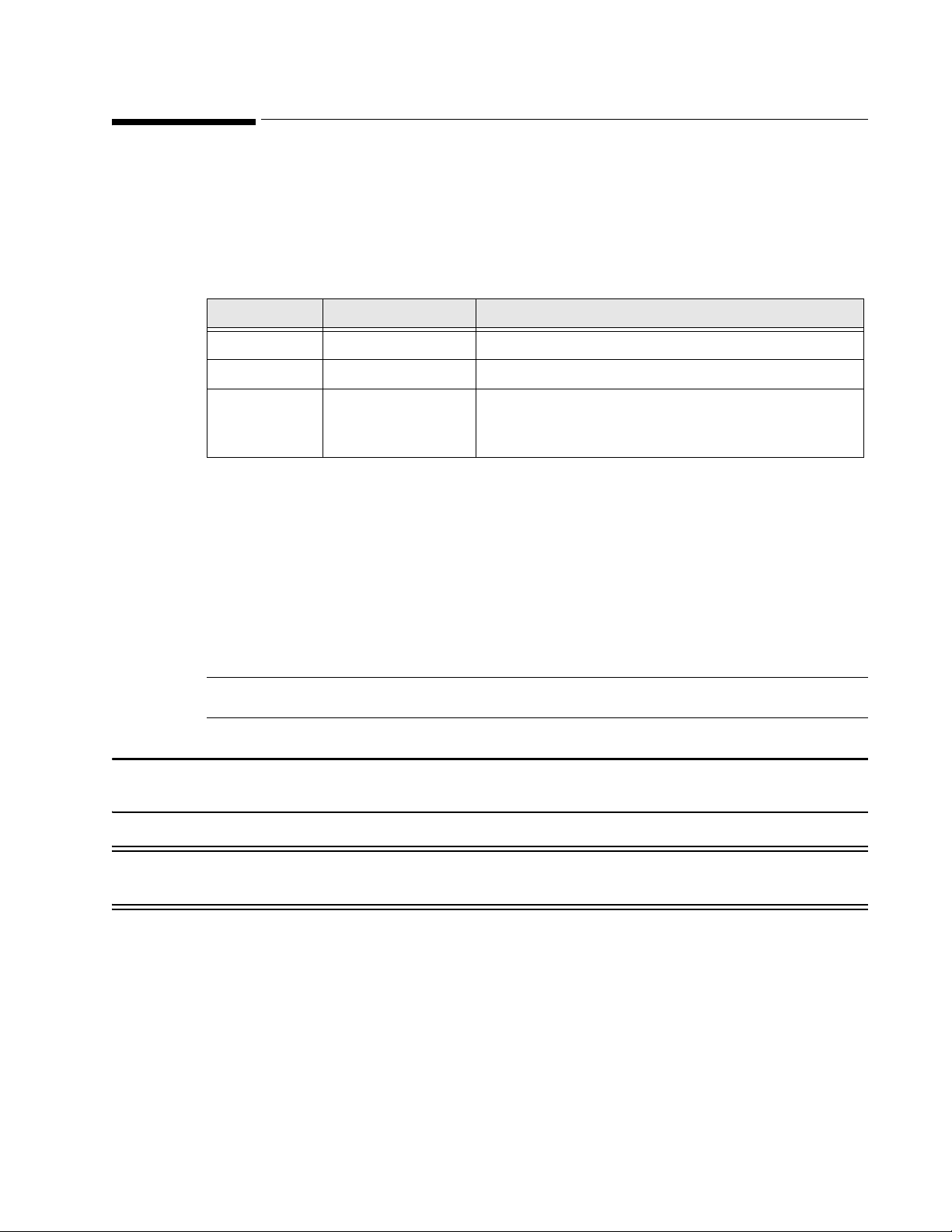
Text Formatting
The following typographical conventions are used in this guide.
Typeface Usage Example
Bold System keys Press the Main Screen key.
Special bold User interface text Open the System Menu.
Italic Variables,
ocument titles
d
• <product name>-<hardware
configuration>-<software version>.cfg
• SureSigns VM Series Instructions for Use
Decimal Points
Because the SureSigns monitor uses a period (.) to indicate a decimal point in decimal numbers (for
example, 10.0), all decimal numbers in this guide use a period as a decimal point. Commas are not
used as decimal points.
Notes, Cautions, and Warnings
The guide uses the following conventions for Notes, Cautions, and Warnings.
Note — A Note calls attention to an important point in the text.
Caution A Caution calls attention to a condition or possible situation that could damage or destroy the
product or the user’s work.
Warning A Warning calls attention to a condition or possible situation that could cause injury to the user
and/or patient.
SureSigns VS4 Service Guide iii
Page 6
Explanation of Symbols
40°C
-20°C
90%
15%
90%
15%
0123
1014 hPA
708 hPA
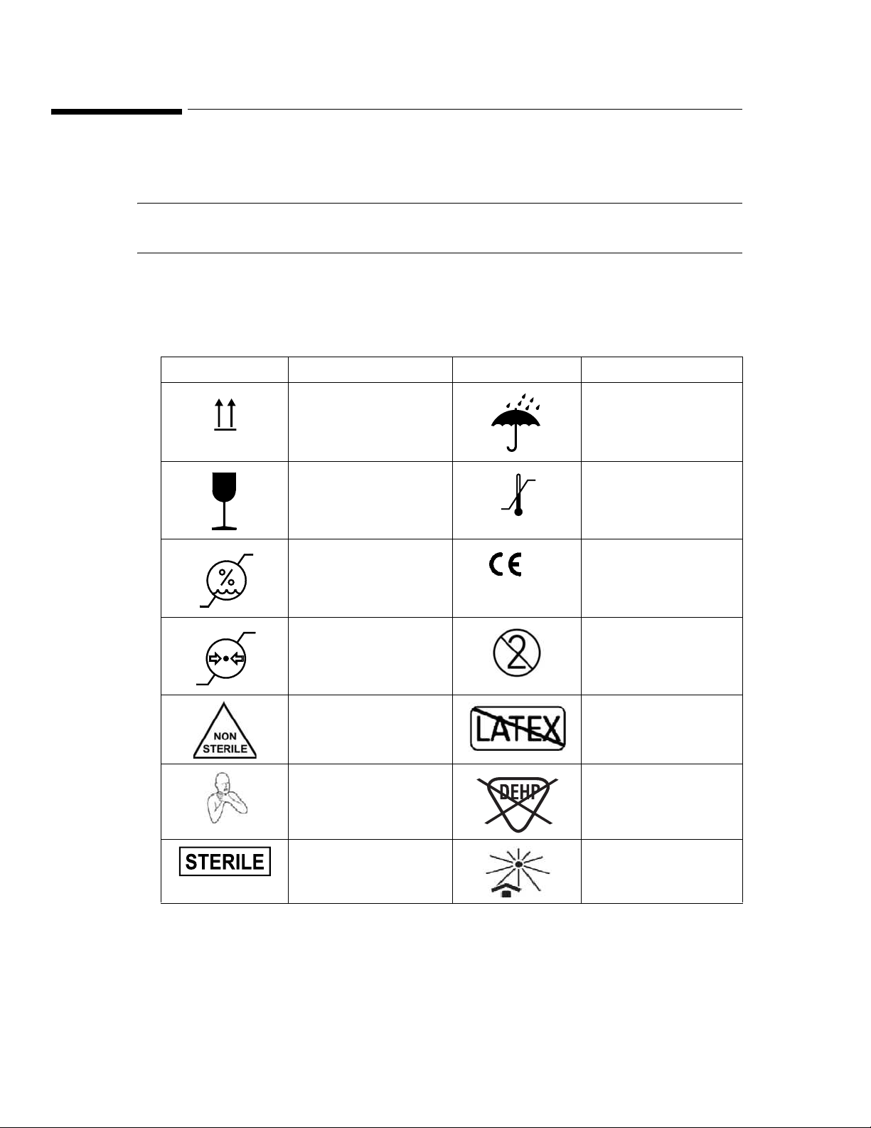
This section explains the symbols that appear on the monitor and its packaging
Packaging
Note — The symbols that appear on your monitor depend on the monitor model and its
configured options.
The following symbols appear on the monitor’s packaging:.
Symbol Description Symbol Description
Keep upright Keep dry
Fragile, handle with
care
Humidity limitation
Atmospheric pressure
limitation
Temperature limitation
CE marking
Single Use
Non-Sterile No Latex
Choking Hazard DEHP-free
Sterile Keep out of sun
iv SureSigns VS4 Service Guide
Page 7
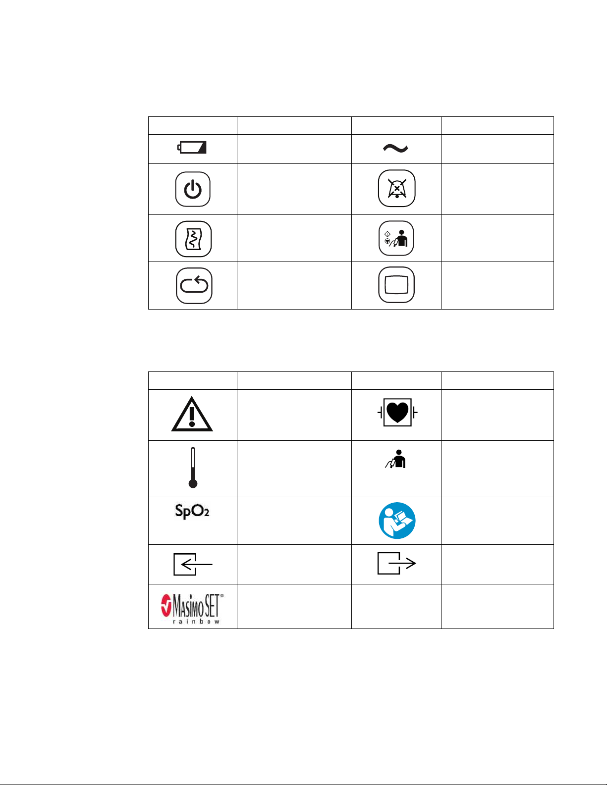
User-Control Symbols
The following symbols appear on and near the user-control buttons on the front of the monitor:.
Symbol Description Symbol Description
Battery charging LED AC Power LED
On/Standby key Alarm Silence key
Print key NBP key
NBP Interval key Main Screen key
Measurement Connector Symbols
The following symbols appear next to the measurement connectors on the side of the monitor:.
Symbol Description Symbol Description
Caution, consult
accompanying
documents
Temperature connector NBP connector
SpO2 connector Follow Instructions for
CO2 input connector CO2 output connector
Masimo SET® (red and
black symbol)
Defibrillator Proof Type
CF applied part
Use (Blue safety
symbol)
SureSigns VS4 Service Guide v
Page 8
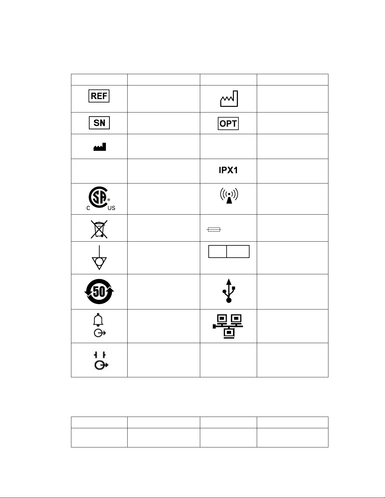
Rear Panel Label Symbols
Rx only
ICES-001
100-240V ~ 50/60Hz 120VA
T1.6A 250V
EC REP
FCC ID
IC ID
The following symbols appear on the rear panel label of the monitor:.
Symbol Description Symbol Description
Catalog number Date of manufacture
Date of first calibration
Serial number Option number
Manufacturer’s Name
and Address
Canadian ISM
requirement
CSA mark RF Interference
Compliance with WEEE
standard
Equipotential
grounding post
EUFP
(Environmentally
frie
ndly
use period - China)
Nurse call connector Ethernet port
Prescription Use Only
(US Federal Law)
Ingress protection to
vertically falling water
drops
Input power and fuse
rating
Authorized EU
Representative
USB port
Radio Symbols
vi SureSigns VS4 Service Guide
ECG Out port
This port is not
av
ailable for use.
The following symbols are available when the monitor uses the radio accessory:
Symbol Description Symbol Description
FCC label for radio
Industry Canada label
for radio
Page 9
0123
Symbol Description Symbol Description
Internal Symbols
The following symbols are located inside the monitor::
Symbol Description Symbol Description
Side Mount Accessories
The following symbols are located on the side mount:
CE marking and
ier for radio
identif
Dangerous voltage
(Yellow safety symbol)
Protective earth ground
RF Interference
Electrostatic sensitive
device handling
Symbol Description Symbol Description
Eject key Consult instructions for
Scan key
Probe cover installed Probe cover not
Timer key
Regulatory and Safety Specifications
Declaration
use
°C/°
F key
installed
The SureSigns VS4 monitor is a Class IIb device and complies with the requirements of the Council
Directive 93/42/EEC of 14 June 1993 concerning medical devices and carries CE-marking
accordingly.
SureSigns VS4 Service Guide vii
Page 10
The radio device used in the SureSigns VS4 vital signs monitors are in compliance with the essential
requirements and other relevant provisions of Directive 1999/5/EC (Radio Equipment and
Telecommunications Terminal Equipment Directive).
Authorized EU Representative
Philips Medizin Systeme Böblingen GmbH
Hewlett-Packard Str. 2
71034 Böblingen
Germany
Australia Sponsor
Philips Healthcare
65 Epping Road, North Ryde
NSW, Australia 2113
Rx Only
Caution United States Federal Law restricts this device to sale by or on the order of a physician.
Safety Standards
Parameter Specification
IEC 60601-1:2005 +CORR. 1 (2006) + CORR. 2 (2007)
IEC 60601-1-2:2007 (R2012)
IEC 80601-2-30:2009, IEC 60601-1-6:2010,
IEC 60601-1-8:2006
IEC 60601-2-49:2011, ISO 80601-2-55:2011
ISO 80601-2-56:2009, ISO 80601-2-61:2011
Protection Class Class I, internally powered equipment, per IEC 60601-1
Degree of Protection Type CF defibrillator-proof: per IEC 60601-1
Mode of Operation Continuous
Protection Against Hazards of
Ignition of Flammable
Anaesthetic Mixtures
Equipment is not suitable for use in the presence of a flammable
anaesthetic mixture with air or oxygen or nitrous oxide, per IEC
60601-1
viii SureSigns VS4 Service Guide
Page 11

Contents
1. Overview
Intended Audience. . . . . . . . . . . . . . . . . . . . . . . . . . . . . . . . . . . . . . . . . . . . . . . . . . . . . . . . . . . . . . . . . . . . . . . . . . . . . . . . . . 1-1
About This Guide . . . . . . . . . . . . . . . . . . . . . . . . . . . . . . . . . . . . . . . . . . . . . . . . . . . . . . . . . . . . . . . . . . . . . . . . . . . . . . . . . . . 1-1
Navigation Controls . . . . . . . . . . . . . . . . . . . . . . . . . . . . . . . . . . . . . . . . . . . . . . . . . . . . . . . . . . . . . . . . . . . . . . . . . . . . . . . . . 1-1
SureSigns VS4 Documentation . . . . . . . . . . . . . . . . . . . . . . . . . . . . . . . . . . . . . . . . . . . . . . . . . . . . . . . . . . . . . . . . . . . . . . . 1-1
2. Performing Routine Maintenance
Recommended Frequency . . . . . . . . . . . . . . . . . . . . . . . . . . . . . . . . . . . . . . . . . . . . . . . . . . . . . . . . . . . . . . . . . . . . . . . . . . 2-1
Routine Safety and Operational Checks . . . . . . . . . . . . . . . . . . . . . . . . . . . . . . . . . . . . . . . . . . . . . . . . . . . . . . . . . . . . . . 2-2
Cleaning and Disinfecting the Monitor . . . . . . . . . . . . . . . . . . . . . . . . . . . . . . . . . . . . . . . . . . . . . . . . . . . . . . . . . . . . . . . . 2-2
Maintaining the Battery . . . . . . . . . . . . . . . . . . . . . . . . . . . . . . . . . . . . . . . . . . . . . . . . . . . . . . . . . . . . . . . . . . . . . . . . . . . . . 2-2
About the Battery. . . . . . . . . . . . . . . . . . . . . . . . . . . . . . . . . . . . . . . . . . . . . . . . . . . . . . . . . . . . . . . . . . . . 2-2
Viewing Battery Information . . . . . . . . . . . . . . . . . . . . . . . . . . . . . . . . . . . . . . . . . . . . . . . . . . . . . . . . . .2-2
Reconditioning the Battery . . . . . . . . . . . . . . . . . . . . . . . . . . . . . . . . . . . . . . . . . . . . . . . . . . . . . . . . . . .2-4
Replacing the Battery . . . . . . . . . . . . . . . . . . . . . . . . . . . . . . . . . . . . . . . . . . . . . . . . . . . . . . . . . . . . . . . .2-4
Battery Messages and Alarms . . . . . . . . . . . . . . . . . . . . . . . . . . . . . . . . . . . . . . . . . . . . . . . . . . . . . . . .2-4
Technical Alarms . . . . . . . . . . . . . . . . . . . . . . . . . . . . . . . . . . . . . . . . . . . . . . . . . . . . . . . . . . . . . . . . 2-4
Error Codes . . . . . . . . . . . . . . . . . . . . . . . . . . . . . . . . . . . . . . . . . . . . . . . . . . . . . . . . . . . . . . . . . . . . .2-4
3. Performance Verification Testing
Overview . . . . . . . . . . . . . . . . . . . . . . . . . . . . . . . . . . . . . . . . . . . . . . . . . . . . . . . . . . . . . . . . . . . . . . . . . . . . . . . . . . . . . . . . . . . 3-1
Testing and Inspection Guidelines. . . . . . . . . . . . . . . . . . . . . . . . . . . . . . . . . . . . . . . . . . . . . . . . . . . . . . . . . . . . . . . . . . . . 3-1
Recommended Frequency . . . . . . . . . . . . . . . . . . . . . . . . . . . . . . . . . . . . . . . . . . . . . . . . . . . . . . . . . . . . . . . . . . . . . . . . . . 3-2
Required Test Equipment . . . . . . . . . . . . . . . . . . . . . . . . . . . . . . . . . . . . . . . . . . . . . . . . . . . . . . . . . . . . . . . . . . . . . . . . . . .3-3
Test Recording . . . . . . . . . . . . . . . . . . . . . . . . . . . . . . . . . . . . . . . . . . . . . . . . . . . . . . . . . . . . . . . . . . . . . . . . . . . . . . . . . . . . .3-4
Accessing the System Menu . . . . . . . . . . . . . . . . . . . . . . . . . . . . . . . . . . . . . . . . . . . . . . . . . . . . . . . . . . . . . . . . . . . . . . . . .3-4
Accessing the System Admin Menu . . . . . . . . . . . . . . . . . . . . . . . . . . . . . . . . . . . . . . . . . . . . . . . . . . . . . . . . . . . . . . . . . .3-5
System Admin Menu Options . . . . . . . . . . . . . . . . . . . . . . . . . . . . . . . . . . . . . . . . . . . . . . . . . . . . . . . . .3-6
Enabling Demo Mode . . . . . . . . . . . . . . . . . . . . . . . . . . . . . . . . . . . . . . . . . . . . . . . . . . . . . . . . . . . . . . . . 3-7
Upgrading the Software . . . . . . . . . . . . . . . . . . . . . . . . . . . . . . . . . . . . . . . . . . . . . . . . . . . . . . . . . . . . . . . . . . . . . . . . . . . . .3-8
Registering for Software Upgrades from Philips InCenter . . . . . . . . . . . . . . . . . . . . . . . . . . . . . . .3-8
Performing Verification Tests . . . . . . . . . . . . . . . . . . . . . . . . . . . . . . . . . . . . . . . . . . . . . . . . . . . . . . . . . . . . . . . . . . . . . . . 3-11
Accessing the System Diagnostics Menu . . . . . . . . . . . . . . . . . . . . . . . . . . . . . . . . . . . . . . . . . . . . . 3-11
Accessing Maintenance Options . . . . . . . . . . . . . . . . . . . . . . . . . . . . . . . . . . . . . . . . . . . . . . . . . . . . . 3-12
Visual Test . . . . . . . . . . . . . . . . . . . . . . . . . . . . . . . . . . . . . . . . . . . . . . . . . . . . . . . . . . . . . . . . . . . . . . . . . . . . . . . . . . . . . . . . 3-13
Power-On Self Test . . . . . . . . . . . . . . . . . . . . . . . . . . . . . . . . . . . . . . . . . . . . . . . . . . . . . . . . . . . . . . . . . . . . . . . . . . . . . . . . 3-13
Alarms Test. . . . . . . . . . . . . . . . . . . . . . . . . . . . . . . . . . . . . . . . . . . . . . . . . . . . . . . . . . . . . . . . . . . . . . . . . . . . . . . . . . . . . . . . 3-14
Test . . . . . . . . . . . . . . . . . . . . . . . . . . . . . . . . . . . . . . . . . . . . . . . . . . . . . . . . . . . . . . . . . . . . . . . . . . . . . . . . . . . . . . . . . 3-14
SpO
2
CO2 Calibration Test . . . . . . . . . . . . . . . . . . . . . . . . . . . . . . . . . . . . . . . . . . . . . . . . . . . . . . . . . . . . . . . . . . . . . . . . . . . . . . . 3-15
Required Test Equipment . . . . . . . . . . . . . . . . . . . . . . . . . . . . . . . . . . . . . . . . . . . . . . . . . . . . . . . . . . . 3-15
Gas Measurement Calibration Check . . . . . . . . . . . . . . . . . . . . . . . . . . . . . . . . . . . . . . . . . . . . 3-15
CO
2
Calibrating the CO
NBP Test . . . . . . . . . . . . . . . . . . . . . . . . . . . . . . . . . . . . . . . . . . . . . . . . . . . . . . . . . . . . . . . . . . . . . . . . . . . . . . . . . . . . . . . . . . 3-17
NBP Accuracy . . . . . . . . . . . . . . . . . . . . . . . . . . . . . . . . . . . . . . . . . . . . . . . . . . . . . . . . . . . . . . . . . . . . . .3-18
NBP Calibration Procedure . . . . . . . . . . . . . . . . . . . . . . . . . . . . . . . . . . . . . . . . . . . . . . . . . . . . . . . . . 3-20
Pneumatic Leakage Test . . . . . . . . . . . . . . . . . . . . . . . . . . . . . . . . . . . . . . . . . . . . . . . . . . . . . . . . . . . . 3-21
Predictive Temperature Test . . . . . . . . . . . . . . . . . . . . . . . . . . . . . . . . . . . . . . . . . . . . . . . . . . . . . . . . . . . . . . . . . . . . . . . . 3-21
Tympanic Temperature Test . . . . . . . . . . . . . . . . . . . . . . . . . . . . . . . . . . . . . . . . . . . . . . . . . . . . . . . . . . . . . . . . . . . . . . . .3-22
Safety Tests . . . . . . . . . . . . . . . . . . . . . . . . . . . . . . . . . . . . . . . . . . . . . . . . . . . . . . . . . . . . . . . . . . . . . . . . . . . . . . . . . . . . . . .3-22
Enclosure Leakage. . . . . . . . . . . . . . . . . . . . . . . . . . . . . . . . . . . . . . . . . . . . . . . . . . . . . . . . . . . . . . . . . .3-23
Expected Test Results . . . . . . . . . . . . . . . . . . . . . . . . . . . . . . . . . . . . . . . . . . . . . . . . . . . . . . . . . .3-23
Expected Test Results . . . . . . . . . . . . . . . . . . . . . . . . . . . . . . . . . . . . . . . . . . . . . . . . . . . . . . . . . .3-23
Ground Integrity . . . . . . . . . . . . . . . . . . . . . . . . . . . . . . . . . . . . . . . . . . . . . . . . . . . . . . . . . . . . . . . . . . . .3-24
Expected Test Results . . . . . . . . . . . . . . . . . . . . . . . . . . . . . . . . . . . . . . . . . . . . . . . . . . . . . . . . . .3-24
Module . . . . . . . . . . . . . . . . . . . . . . . . . . . . . . . . . . . . . . . . . . . . . . . . . . . . . . . . . 3-16
2
SureSigns VS4 Service Guide
Contents-1
Page 12

Patient Leakage Current With Mains Voltage. . . . . . . . . . . . . . . . . . . . . . . . . . . . . . . . . . . . . . . . . 3-24
Expected Test Results . . . . . . . . . . . . . . . . . . . . . . . . . . . . . . . . . . . . . . . . . . . . . . . . . . . . . . . . . 3-24
Nurse Call Relay Test. . . . . . . . . . . . . . . . . . . . . . . . . . . . . . . . . . . . . . . . . . . . . . . . . . . . . . . . . . . . . . . . . . . . . . . . . . . . . . 3-25
Calibrating the Touch Screen . . . . . . . . . . . . . . . . . . . . . . . . . . . . . . . . . . . . . . . . . . . . . . . . . . . . . . . . . . . . . . . . . . . . . . 3-26
4. Troubleshooting
When You Cannot Correct a Problem . . . . . . . . . . . . . . . . . . . . . . . . . . . . . . . . . . . . . . . . . . . . . . . . . 4-1
Viewing System Information . . . . . . . . . . . . . . . . . . . . . . . . . . . . . . . . . . . . . . . . . . . . . . . . . . . . . . . . . . . . . . . . . . . . . . . . . 4-1
Diagnosing a Problem . . . . . . . . . . . . . . . . . . . . . . . . . . . . . . . . . . . . . . . . . . . . . . . . . . . . . . . . . . . . . . . . . . . . . . . . . . . . . . . 4-1
Start-up and Power Sequences . . . . . . . . . . . . . . . . . . . . . . . . . . . . . . . . . . . . . . . . . . . . . . . . . . . . . . . . . . . . . . . . . . . . . .4-2
Troubleshooting Tables . . . . . . . . . . . . . . . . . . . . . . . . . . . . . . . . . . . . . . . . . . . . . . . . . . . . . . . . . . . . . . . . . . . . . . . . . . . . .4-3
Power Problems . . . . . . . . . . . . . . . . . . . . . . . . . . . . . . . . . . . . . . . . . . . . . . . . . . . . . . . . . . . . . . . . . . . .4-4
Display Problems . . . . . . . . . . . . . . . . . . . . . . . . . . . . . . . . . . . . . . . . . . . . . . . . . . . . . . . . . . . . . . . . . . .4-5
Alarm Problems . . . . . . . . . . . . . . . . . . . . . . . . . . . . . . . . . . . . . . . . . . . . . . . . . . . . . . . . . . . . . . . . . . . . .4-5
NBP Problems. . . . . . . . . . . . . . . . . . . . . . . . . . . . . . . . . . . . . . . . . . . . . . . . . . . . . . . . . . . . . . . . . . . . . . 4-6
Temperature Measurement Problems . . . . . . . . . . . . . . . . . . . . . . . . . . . . . . . . . . . . . . . . . . . . . . . . 4-8
Measurement Problems . . . . . . . . . . . . . . . . . . . . . . . . . . . . . . . . . . . . . . . . . . . . . . . . . . . . . . . 4-9
SpO
2
Measurement Problems . . . . . . . . . . . . . . . . . . . . . . . . . . . . . . . . . . . . . . . . . . . . . . . . . . . . . . 4-9
etCO
2
Navigation Wheel, Touch Screen, and Key Problems . . . . . . . . . . . . . . . . . . . . . . . . . . . . . . . . . .4-10
Recorder Problems . . . . . . . . . . . . . . . . . . . . . . . . . . . . . . . . . . . . . . . . . . . . . . . . . . . . . . . . . . . . . . . . . 4-11
Nurse Call Problems . . . . . . . . . . . . . . . . . . . . . . . . . . . . . . . . . . . . . . . . . . . . . . . . . . . . . . . . . . . . . . . . 4-11
USB Hub Problems . . . . . . . . . . . . . . . . . . . . . . . . . . . . . . . . . . . . . . . . . . . . . . . . . . . . . . . . . . . . . . . . . 4-12
Security Problems . . . . . . . . . . . . . . . . . . . . . . . . . . . . . . . . . . . . . . . . . . . . . . . . . . . . . . . . . . . . . . . . . . 4-12
Error Codes. . . . . . . . . . . . . . . . . . . . . . . . . . . . . . . . . . . . . . . . . . . . . . . . . . . . . . . . . . . . . . . . . . . . . . . . . . . . . . . . . . . . . . . . 4-13
Running System Diagnostics . . . . . . . . . . . . . . . . . . . . . . . . . . . . . . . . . . . . . . . . . . . . . . . . . . . . . . . . . . . . . . . . . . . . . . . 4-32
Running the Self Test . . . . . . . . . . . . . . . . . . . . . . . . . . . . . . . . . . . . . . . . . . . . . . . . . . . . . . . . . . . . . . . . . . . . . . . . . . . . . 4-32
Testing the Recorder . . . . . . . . . . . . . . . . . . . . . . . . . . . . . . . . . . . . . . . . . . . . . . . . . . . . . . . . . . . . . . . . . . . . . . . . . . . . . . 4-34
Testing the Navigation Wheel and Keys . . . . . . . . . . . . . . . . . . . . . . . . . . . . . . . . . . . . . . . . . . . . . . . . . . . . . . . . . . . . 4-34
Testing the Display. . . . . . . . . . . . . . . . . . . . . . . . . . . . . . . . . . . . . . . . . . . . . . . . . . . . . . . . . . . . . . . . . . . . . . . . . . . . . . . . 4-36
Testing the Speaker . . . . . . . . . . . . . . . . . . . . . . . . . . . . . . . . . . . . . . . . . . . . . . . . . . . . . . . . . . . . . . . . . . . . . . . . . . . . . . . 4-36
Testing the Battery LED . . . . . . . . . . . . . . . . . . . . . . . . . . . . . . . . . . . . . . . . . . . . . . . . . . . . . . . . . . . . . . . . . . . . . . . . . . . .4-37
Viewing and Resetting Tracked Parameters . . . . . . . . . . . . . . . . . . . . . . . . . . . . . . . . . . . . . . . . . . . . . . . . . . . . . . . . . .4-37
Resetting Parameters . . . . . . . . . . . . . . . . . . . . . . . . . . . . . . . . . . . . . . . . . . . . . . . . . . . . . . . . . . . . . . .4-37
Viewing, Printing, and Exporting the Error Log. . . . . . . . . . . . . . . . . . . . . . . . . . . . . . . . . . . . . . . . . . . . . . . . . . . . . . . 4-38
Clearing Patient Data . . . . . . . . . . . . . . . . . . . . . . . . . . . . . . . . . . . . . . . . . . . . . . . . . . . . . . . . . . . . . . . . . . . . . . . . . . . . . 4-40
5. Repairing the Monitor
Disassembling the Monitor . . . . . . . . . . . . . . . . . . . . . . . . . . . . . . . . . . . . . . . . . . . . . . . . . . . . . . . . . . . . . . . . . . . . . . . . . . 5-1
Tools Required for Service. . . . . . . . . . . . . . . . . . . . . . . . . . . . . . . . . . . . . . . . . . . . . . . . . . . . . . . . . . . . . . . . . . . . . . . . . . .5-2
Shutting Down the Monitor . . . . . . . . . . . . . . . . . . . . . . . . . . . . . . . . . . . . . . . . . . . . . . . . . . . . . . . . . . . . . . . . . . . . . . . . . .5-3
Removing the Battery . . . . . . . . . . . . . . . . . . . . . . . . . . . . . . . . . . . . . . . . . . . . . . . . . . . . . . . . . . . . . . . . . . . . . . . . . . . . . . .5-3
Reinstalling the Battery . . . . . . . . . . . . . . . . . . . . . . . . . . . . . . . . . . . . . . . . . . . . . . . . . . . . . . . . . . . . . .5-5
Removing a Fuse . . . . . . . . . . . . . . . . . . . . . . . . . . . . . . . . . . . . . . . . . . . . . . . . . . . . . . . . . . . . . . . . . . . . . . . . . . . . . . . . . . 5-6
Removing the Predictive Temperature Module and Probe Cover Holder . . . . . . . . . . . . . . . . . . . . . . . . . . . . . . . 5-6
Reinstalling the Predictive Temperature Module . . . . . . . . . . . . . . . . . . . . . . . . . . . . . . . . . . . . . . 5-9
Removing the Tympanic Temperature Module . . . . . . . . . . . . . . . . . . . . . . . . . . . . . . . . . . . . . . . . . . . . . . . . . . . . . . . 5-11
Removing the Temporal Temperature Module . . . . . . . . . . . . . . . . . . . . . . . . . . . . . . . . . . . . . . . . . . . . . . . . . . . . . . . 5-13
Removing the CO
Separating the Front and Rear Case Assemblies. . . . . . . . . . . . . . . . . . . . . . . . . . . . . . . . . . . . . . . . . . . . . . . . . . . . . . 5-16
Removing the Faceplate or Recorder . . . . . . . . . . . . . . . . . . . . . . . . . . . . . . . . . . . . . . . . . . . . . . . . . . . . . . . . . . . . . . . . 5-19
Removing the Main Board Assembly . . . . . . . . . . . . . . . . . . . . . . . . . . . . . . . . . . . . . . . . . . . . . . . . . . . . . . . . . . . . . . . . 5-21
Removing the Fan and Speaker . . . . . . . . . . . . . . . . . . . . . . . . . . . . . . . . . . . . . . . . . . . . . . . . . . . . . . . . . . . . . . . . . . . . 5-25
Replacing the Handle O-Ring . . . . . . . . . . . . . . . . . . . . . . . . . . . . . . . . . . . . . . . . . . . . . . . . . . . . . . . . . . . . . . . . . . . . . . 5-25
Contents-2
SureSigns VS4 Service Guide
Module . . . . . . . . . . . . . . . . . . . . . . . . . . . . . . . . . . . . . . . . . . . . . . . . . . . . . . . . . . . . . . . . . . . . . . . . . 5-15
2
Reassembling the Front and Rear Cases. . . . . . . . . . . . . . . . . . . . . . . . . . . . . . . . . . . . . . . . . . . . . .5-18
Removing the Main Board Assembly . . . . . . . . . . . . . . . . . . . . . . . . . . . . . . . . . . . . . . . . . . . . . . . . .5-21
Reinstalling the Main Board Assembly . . . . . . . . . . . . . . . . . . . . . . . . . . . . . . . . . . . . . . . . . . . . . . 5-24
Page 13

Removing the Front End Assembly . . . . . . . . . . . . . . . . . . . . . . . . . . . . . . . . . . . . . . . . . . . . . . . . . . . . . . . . . . . . . . . . . 5-26
Replacing the SpO2 Board . . . . . . . . . . . . . . . . . . . . . . . . . . . . . . . . . . . . . . . . . . . . . . . . . . . . . . . . . . . . . . . . . . . . . . . . . 5-28
Determining the Type of SpO2 Board. . . . . . . . . . . . . . . . . . . . . . . . . . . . . . . . . . . . . . . . . . . . . . . . 5-28
Removing the Philips SpO
Removing the Power Supply . . . . . . . . . . . . . . . . . . . . . . . . . . . . . . . . . . . . . . . . . . . . . . . . . . . . . . . . . . . . . . . . . . . . . . . . 5-31
Removing the Main Board . . . . . . . . . . . . . . . . . . . . . . . . . . . . . . . . . . . . . . . . . . . . . . . . . . . . . . . . . . . . . . . . . . . . . . . . . 5-33
Resetting the Serial Number . . . . . . . . . . . . . . . . . . . . . . . . . . . . . . . . . . . . . . . . . . . . . . . . . . . . . . . . . . . . . . . . . . . . . . . 5-36
Setting the System Configuration. . . . . . . . . . . . . . . . . . . . . . . . . . . . . . . . . . . . . . . . . . . . . . . . . . . . . . . . . . . . . . . . . . . 5-36
Removing the NBP Module . . . . . . . . . . . . . . . . . . . . . . . . . . . . . . . . . . . . . . . . . . . . . . . . . . . . . . . . . . . . . . . . . . . . . . . . 5-37
Removing the NBP Filter . . . . . . . . . . . . . . . . . . . . . . . . . . . . . . . . . . . . . . . . . . . . . . . . . . . . . . . . . . . 5-38
Removing the AC Power Connector . . . . . . . . . . . . . . . . . . . . . . . . . . . . . . . . . . . . . . . . . . . . . . . . . . . . . . . . . . . . . . . . 5-39
Removing the Communications (LAN) Board . . . . . . . . . . . . . . . . . . . . . . . . . . . . . . . . . . . . . . . . . . . . . . . . . . . . . . . . .5-41
Removing the Battery Connector Board . . . . . . . . . . . . . . . . . . . . . . . . . . . . . . . . . . . . . . . . . . . . . . . . . . . . . . . . . . . . 5-43
Removing the LCD Assembly . . . . . . . . . . . . . . . . . . . . . . . . . . . . . . . . . . . . . . . . . . . . . . . . . . . . . . . . . . . . . . . . . . . . . . 5-44
Removing the Navigation Wheel Assembly Board . . . . . . . . . . . . . . . . . . . . . . . . . . . . . . . . . . . . . . . . . . . . . . . . . . . 5-48
Removing the Touch Screen Board . . . . . . . . . . . . . . . . . . . . . . . . . . . . . . . . . . . . . . . . . . . . . . . . . . . . . . . . . . . . . . . . . 5-50
Removing the Wireless Module . . . . . . . . . . . . . . . . . . . . . . . . . . . . . . . . . . . . . . . . . . . . . . . . . . . . . . . . . . . . . . . . . . . . . 5-51
Removing the Antenna . . . . . . . . . . . . . . . . . . . . . . . . . . . . . . . . . . . . . . . . . . . . . . . . . . . . . . . . . . . . . . . . . . . . . . . . . . . . 5-52
Board . . . . . . . . . . . . . . . . . . . . . . . . . . . . . . . . . . . . . . . . . . . . . . . . . . . 5-29
2
6. Replacement Parts and Assembly Drawings
Spare Parts . . . . . . . . . . . . . . . . . . . . . . . . . . . . . . . . . . . . . . . . . . . . . . . . . . . . . . . . . . . . . . . . . . . . . . . . . . . . . . . . . . . . . . . . .6-1
Assembly Drawings . . . . . . . . . . . . . . . . . . . . . . . . . . . . . . . . . . . . . . . . . . . . . . . . . . . . . . . . . . . . . . . . . . . . . . . . . . . . . . . . 6-4
Power Cords. . . . . . . . . . . . . . . . . . . . . . . . . . . . . . . . . . . . . . . . . . . . . . . . . . . . . . . . . . . . . . . . . . . . . . . . . . . . . . . . . . . . . . . 6-7
A. Theory of Operation
Block Diagram Components . . . . . . . . . . . . . . . . . . . . . . . . . . . . . . . . . . . . . . . . . . . . . . . . . . . . . . . . . . . . . . . . . . . . . . . . .A-1
Block Diagram . . . . . . . . . . . . . . . . . . . . . . . . . . . . . . . . . . . . . . . . . . . . . . . . . . . . . . . . . . . . . . . . . . . . . . A-2
Main Board. . . . . . . . . . . . . . . . . . . . . . . . . . . . . . . . . . . . . . . . . . . . . . . . . . . . . . . . . . . . . . . . . . . . . . . . . A-2
Front End Board . . . . . . . . . . . . . . . . . . . . . . . . . . . . . . . . . . . . . . . . . . . . . . . . . . . . . . . . . . . . . . . . . . . . A-3
Communications (LAN) Board . . . . . . . . . . . . . . . . . . . . . . . . . . . . . . . . . . . . . . . . . . . . . . . . . . . . . . . A-4
Nurse Call Contacts . . . . . . . . . . . . . . . . . . . . . . . . . . . . . . . . . . . . . . . . . . . . . . . . . . . . . . . . . . . . . A-4
Front Panel Assembly . . . . . . . . . . . . . . . . . . . . . . . . . . . . . . . . . . . . . . . . . . . . . . . . . . . . . . . . . . . . . . . A-4
Speaker . . . . . . . . . . . . . . . . . . . . . . . . . . . . . . . . . . . . . . . . . . . . . . . . . . . . . . . . . . . . . . . . . . . . . . . . . . . . A-5
Navigation Wheel . . . . . . . . . . . . . . . . . . . . . . . . . . . . . . . . . . . . . . . . . . . . . . . . . . . . . . . . . . . . . . . . . . . A-5
Power Supply Module . . . . . . . . . . . . . . . . . . . . . . . . . . . . . . . . . . . . . . . . . . . . . . . . . . . . . . . . . . . . . . A-5
Power Management . . . . . . . . . . . . . . . . . . . . . . . . . . . . . . . . . . . . . . . . . . . . . . . . . . . . . . . . . . . . A-5
Recorder . . . . . . . . . . . . . . . . . . . . . . . . . . . . . . . . . . . . . . . . . . . . . . . . . . . . . . . . . . . . . . . . . . . . . . . . . . . A-5
NBP Assembly and Circuitry . . . . . . . . . . . . . . . . . . . . . . . . . . . . . . . . . . . . . . . . . . . . . . . . . . . . . . . . . A-6
Philips SpO
Masimo SpO2. . . . . . . . . . . . . . . . . . . . . . . . . . . . . . . . . . . . . . . . . . . . . . . . . . . . . . . . . . . . . . . . . . . . . . . A-6
Predictive Temperature Module . . . . . . . . . . . . . . . . . . . . . . . . . . . . . . . . . . . . . . . . . . . . . . . . . . . . . A-7
Predictive Measurements. . . . . . . . . . . . . . . . . . . . . . . . . . . . . . . . . . . . . . . . . . . . . . . . . . . . . . . . A-7
Monitored Measurements . . . . . . . . . . . . . . . . . . . . . . . . . . . . . . . . . . . . . . . . . . . . . . . . . . . . . . . A-7
Tympanic Temperature Module. . . . . . . . . . . . . . . . . . . . . . . . . . . . . . . . . . . . . . . . . . . . . . . . . . . . . . A-7
Temporal Temperature Module . . . . . . . . . . . . . . . . . . . . . . . . . . . . . . . . . . . . . . . . . . . . . . . . . . . . . . A-8
Processing . . . . . . . . . . . . . . . . . . . . . . . . . . . . . . . . . . . . . . . . . . . . . . . . . . . . . . . . . . . . . A-6
2
B. Electromagnetic Compatibility
Instructions for Use . . . . . . . . . . . . . . . . . . . . . . . . . . . . . . . . . . . . . . . . . . . . . . . . . . . . . . . . . . . . . . . . . .B-1
Reducing Electromagnetic Interference. . . . . . . . . . . . . . . . . . . . . . . . . . . . . . . . . . . . . . . . . . . . . . . . B-1
Restrictions for Use . . . . . . . . . . . . . . . . . . . . . . . . . . . . . . . . . . . . . . . . . . . . . . . . . . . . . . . . . . . . . . . . . B-2
Emissions and Immunity. . . . . . . . . . . . . . . . . . . . . . . . . . . . . . . . . . . . . . . . . . . . . . . . . . . . . . . . . . . . . B-2
Guidance and Manufacturer’s Declaration . . . . . . . . . . . . . . . . . . . . . . . . . . . . . . . . . . . . . . . . . . . . B-2
Recommended Separation Distances . . . . . . . . . . . . . . . . . . . . . . . . . . . . . . . . . . . . . . . . . . . . . . . . B-5
SureSigns VS4 Service Guide
Contents-3
Page 14

Contents-4
SureSigns VS4 Service Guide
Page 15
Intended Audience
This guide is for biomedical engineers or technicians responsible for troubleshooting, repairing,
and maintaining Philips patient monitoring systems.
About This Guide
This guide includes information about current hardware. For information about earlier versions of
the hardware, see an earlier version of the Service Guide on the SureSigns VS3 and VS4 Service
Documentation CD.
Navigation Controls
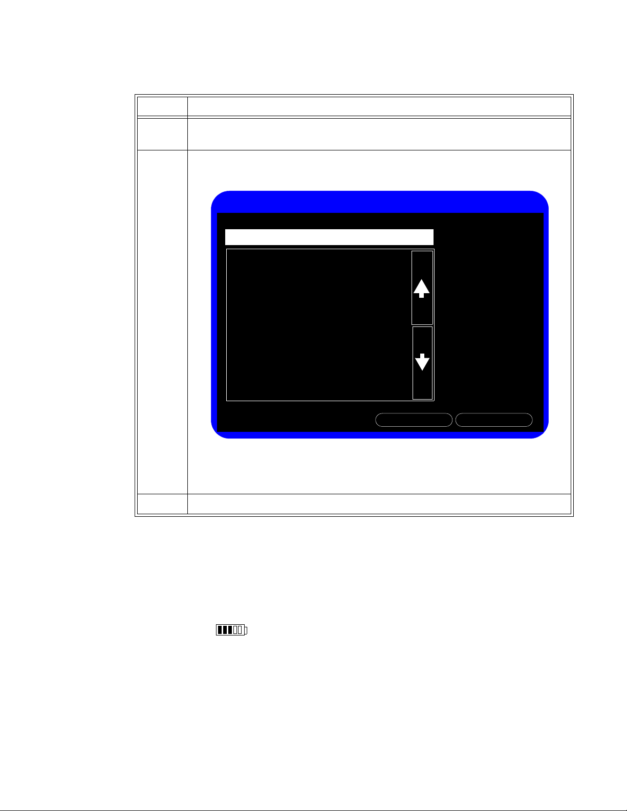
The following table describes how to use the navigation controls on the SureSigns® VS4 monitor:
1
Overview
Action Description
Select Touch a button, menu, or list item on
Press Press a front panel key
Enter data using
the nume
keypad and
keyboard
Select or clear
check boxes
Scroll Touch the list and drag your finger to scro
ric
Touch the item to display the numeric keypad or the keyboard. Touch
the values, and then touch OK to close the keypad or keyboard.
Touch a check box to select or clear it.
Up or Down arrows to display the next or previous page in the list.
(You can also use the wheel to scroll and select items in the list.)
A scroll bar to the right of the list indicates the current location in the
list.
Touch an item to select it.
SureSigns VS4 Documentation
SureSigns VS4 documentation includes:
the touch screen to select it.
or press the wheel.
ll up and down. Touch the
• SureS
• SureSigns VS4 Instructions f
igns VS4 Installation and Configuration Guide: Provides instructions for unpacking,
installing, and connecting all hardware. Includes initial testing and configuration
procedures. Also includes instructions for returning the monitor.
or Use: Provides information for day to day operation of the
monitor. Also includes safety information, monitor specifications, and a list of compatible
accessories.
Overview
SureSigns VS4 Service Guide 1-1
Page 16

SureSigns VS4 Documentation
• SureSigns VS4 Quick Card: Provides brief descriptions of commonly used functions.
• SureSigns VS4 Service Guide: Provides instructions for repairing and testing the monitor.
Includes assembly diagrams, spare parts lists and troubleshooting information.
• SureSigns VS4 Data Export Guide: Provides detailed information about the HL7 data export
feature, including HL7 message syntax and procedures for exporting HL7 data from the
monitor.
• SureSigns VS4 Network Configuration Guide: Provides instructions for configuring your
monitor to connect to a network using a wired LAN connection, a wireless LAN connection, or
an RS-232 serial adapter.
• SureSigns VS4 QuickCapture Configuration Guide: Provides instructions for configuring the
QuickCapture feature on the monitor. Includes information about defining the set of
observations and assessments, creating a file to import that information into the monitor, and
mapping the exported data to an EHR.
• SureSigns VS4 QuickAlerts Configuration Guide: Provides instructions for planning and
configuring the QuickAlerts feature on the SureSigns VS4 monitor. Includes information about
defining the set of alert messages, creating a file to import that information into the monitor,
and mapping the exported data to an EHR.
Overview
1-2 SureSigns VS4 Service Guide
Page 17
Performing Routine Maintenance
Recommended Frequency
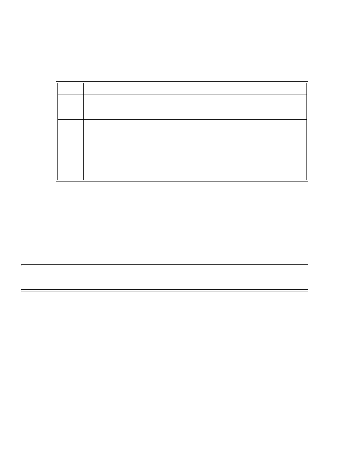
Perform the maintenance procedures at the recommended frequency shown in the following
table.
2
Caution The frequency recommendations in the following table do not supersede local requirements.
Always perform locally required testing in addition to the testing in this chapter.
Maintenance Procedure Frequency
Routine Safety and Operational Checks
• Visual Inspection of exterior for damage Before use.
• Inspection of labels for legibility Before use.
Cleaning and Disinfecting According to your institution’s policy or
between each patient. For complete
cleaning instructions, see the Instructions for
Use provided with your monitor.
Maintaining the Battery
• Charging As needed.
• Reconditioning When the Max Error is 10% or greater.
Warning The monitor must be connected to a three-wire, grounded hospital-grade receptacle. Do not
remove the grounding connector from the power plug or use extensions cords or adapters of
any type.
If there is any doubt about the integrity of the protective earth conductor arrangement,
operate the device on internal battery power until the AC power supply protective conductor
is fully functional.
Measure the device's leakage current whenever an external device is connected to the serial
port. Leakage current must not exceed 100 microamperes. See “Safety Tests” on page 3-22.
Warning MR-unsafe!
Do not expose the device to a magnetic resonance (MR) environment.
• The device may present a risk of projectile injury due to the presence of ferromagnetic
materials which can be attracted by the MR magnet core.
• Thermal injury and burns may occur due to the metal components of the device which can
heat during MR scanning.
• The device may generate artifacts in the MR image.
• The device may not function properly due to the strong magnetic and radio frequency
fields generated by the MR scanner.
Performing Routine Maintenance
SureSigns VS4 Service Guide 2-1
Page 18

Routine Safety and Operational Checks
Routine Safety and Operational Checks
Philips recommends that you regularly:
• Visually inspect the monitor exterior for damage.
• Ensure the vents are free of dust.
• Inspect the monitor labels for legibility.
If the labels on the rear case are not legible, you must replace the rear case. If the serial
number label is not legible, you must return the monitor for label replacement. For detailed
information, see “Visual Test” on page 3-13.
Philips recommends that you perform certain test and verification checks at least once a year and
after each repair. For complete information about performing verification testing and checks, see
Chapter 3, “Performance Verification Testing.”
Cleaning and Disinfecting the Monitor
To clean or disinfect your monitor, use only cleaning agents approved by Philips. For complete
cleaning instructions, see the Instructions for Use provided with your monitor.
Maintaining the Battery
About the Battery
The rechargeable lithium ion battery used in the monitor is a smart battery with built-in circuitry
that communicates battery status information to the monitor. Battery power lasts a minimum of
four hours of continuous monitoring with no printing and one NBP measurement every 15 minutes.
Observe these guidelines:
• If a battery shows damage or signs of leakage, replace it immediately.
• Never use a faulty battery in the monitor.
• Never dispose of the battery in a normal waste container.
• Never leave a battery inside the monitor if it is not used for a long period of time.
• Never store a battery that is more than 50% charged.
Note — For information about the battery status indicators, see the Instructions for Use provided
with your monitor.
Viewing Battery Information
As a battery ages, its capacity decreases and the battery status indicator becomes increasingly less
accurate, relative to the total number of charges and discharges. Select the Battery Info button to
display information about the battery.
Performing Routine Maintenance
2-2 SureSigns VS4 Service Guide
Page 19
To view information about the battery:
Battery Info
06/27/13
95
Manufact. Date
Cycle Count
2%Max Error
ReturnRecondition
EONEMOLI
LION
Manufacturer
Chemistry
#17403Serial Number:
99%
97%
Relative Charge
Absolute Charge
E013RBattery Name
12503 (mV)Voltage
664 (mA)Current
299.50 (K) 26.50(C)Temperature
7100 (mAH)Full Capacity
7200 (mAH)Design Capacity
Parameter
Value
Step
Maintaining the Battery
1 Open the Sy
on page 3-11.
2 Select the
Battery Info button.
The Battery Info window opens.
stem Diagnostics Menu. See “Accessing the System Diagnostics Menu”
The Battery Info
including:
Note — If the message, No data from battery. Please see Service Guide. appears,
you must reseat the battery. For detailed information, see “Removing the Battery”
on page 5-3.
3 To view the entire list of results, select the list to
window provides detailed information about battery capacity and charging status,
• Cycle Count: The number of full charge and discharge cycles calculated by the battery.
• Max Error: The expected margin of error in the state of the charge calculation. The Max Error
value is the difference between the Relative Charge value and the Absolute Charge value.
• Relative Charge: The predicted remaining battery capacity, expressed as a percentage of Full
Capacity. The value in the Relative Charge field decreases as the battery ages. The Battery
Status icon
is a graphic representation of the Relative Charge.
• Absolute Charge: The predicted remaining battery capacity, expressed as a percentage of
Design Capacity.
ll Capacity: The predicted capacity of the battery when it is fully charged. The value in the
• Fu
Full Capacity field decreases as the battery ages. The difference between the value in the
Full Capacity field and the value in the Design Capacity field is an indication of battery
condition.
sign Capacity: The capacity of a new battery.
• De
activate scrolling.
Performing Routine Maintenance
SureSigns VS4 Service Guide 2-3
Page 20
Maintaining the Battery
Reconditioning the Battery
Reconditioning the battery reduces the Max Error value, and in turn, increases the accuracy of the
Relative Charge. Philips recommends that you condition the battery by fully discharging and
recharging it when the Max Error is 10% or greater.
Step
1 Open the Battery Info window.
2 Disconnect the monitor from
3 Select Recon
The Relative Charge percentage will decrease to 0%.
4 When the monitor shuts down, connect the monitor to the power source and allow
the ba
5 Repeat step 1 through step 4.
Note — If the battery does not recharge after four reconditioning cycles, replace it.
Replacing the Battery
Replace the battery if the following conditions occur:
• After reconditioning, if the monitor operates for less than one hour on a fully charged battery
before the low battery (Low Batt) alarm occurs, or
•The Max Error cannot be brought <= 8% after several recondition cycles, or
•The Full Capacity is 50% or less of the Design Capacity.
For information about replacing the battery, see “Removing the Battery” on page 5-3.
See “Viewing Battery Information” on page 2-2.
the power source.
dition.
ttery to recharge to 100%.
Warning Dispose of used batteries in an environmentally responsible manner. Do not dispose of the
battery in normal waste containers. Consult your hospital administrator to find out about local
arrangements.
Battery Messages and Alarms
The condition of the battery is reported by technical alarms and error codes.
Technical Alarms
The following battery technical alarms appear in the message area:
• Low Batt — Remaining battery power is less than 30%.
• E
xtreme Low Batt — Remaining battery power is less than 21%.
Error Codes
An error code (for example, 257 System Error, indicating Battery charger power failure) appears in
the Error Log. To view the Error Log, see “Viewing, Printing, and Exporting the Error Log” on
page 4-38. For a complete list of error codes and actions
Performing Routine Maintenance
2-4 SureSigns VS4 Service Guide
to take, see Chapter 4, “Troubleshooting.”
Page 21

Overview
3
Performance Verification Testing
This chapter includes the following information:
• Testing and inspection guidelines
• Recommended frequency of performance tests
• Test procedures following monitor repair or during routine maintenance
• NBP calibration procedure
If the monitor fails any test, it must be repaired before it is returned to use.
Note — The procedures in this chapter assume knowledge of basic monitor operation. For
details about using the monitor, see the Instructions for Use provided with your
monitor.
Testing and Inspection Guidelines
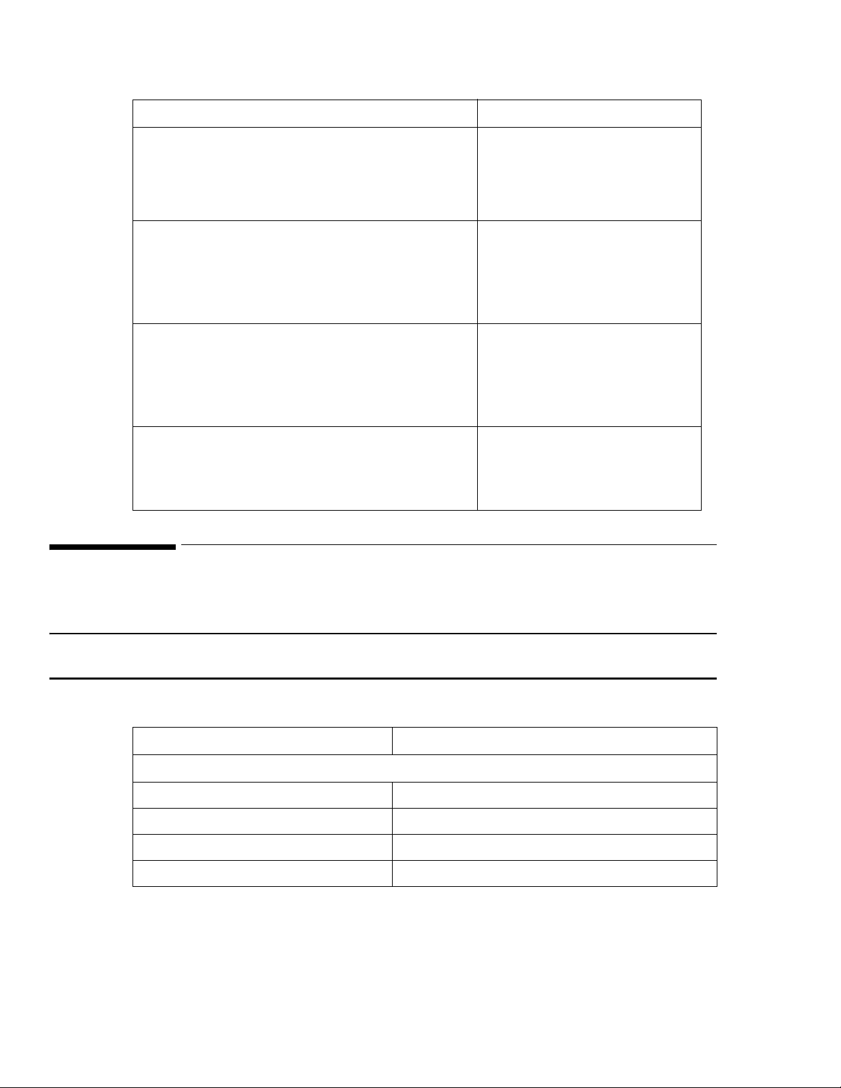
The following table lists the tests that Philips requires that you complete after performing
monitor repairs or upgrading the software.
For information about routine maintenance procedures, see Chapter 2, “Performing Routine
Maintenance.”
For information about repair procedures, see Chapter 5, “Repairing the Monitor.”
After Complete These Tests
Upgrading the software • Power-on self test
Opening the monitor for any reason • Power-on self test
Replacing any internal parts (except NBP parts, SpO2
board)
Replacing the NBP module or parts • Power-on self test
• Verify that your system
settings are preserved
• Alarms test
• Pneumatic leakage test
• All safety tests
• Power-on self test
• Pneumatic leakage test
• All safety tests
• NBP test
• Pneumatic leakage test
• All safety tests
Performance Verification Testing
SureSigns VS4 Service Guide 3-1
Page 22
Recommended Frequency
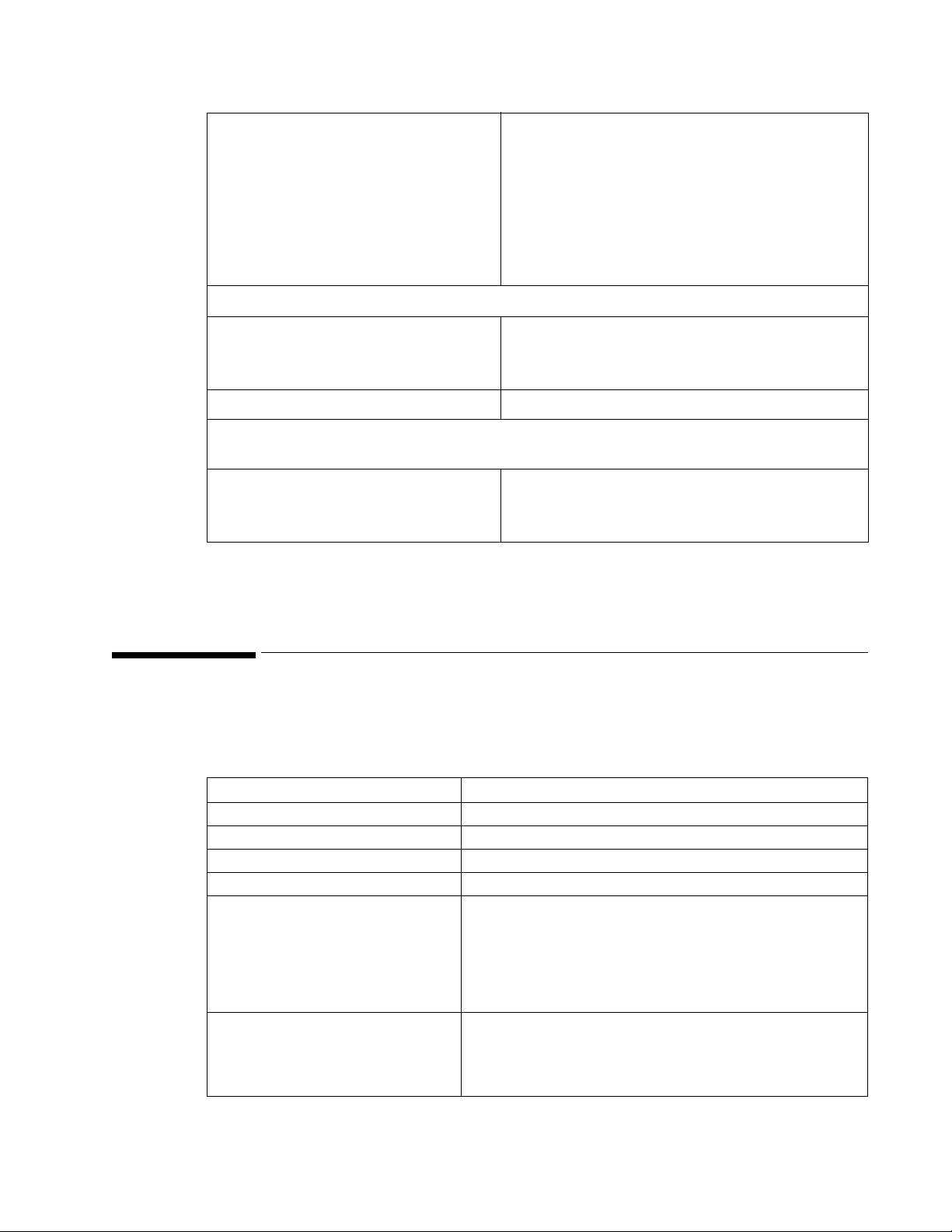
After Complete These Tests
Replacing the Philips SpO2 board
Note — Monitors with the Masimo SpO
board must
2
be returned to Philips for Masimo SpO2 board
replacement. Contact the Philips Customer Care Center
or your local Philips representative.
• Power-on self test
•SpO
2
• Pneumatic leakage test
• All safety tests
Replacing the temperature module • Power-on self test
• Alarms test
• Pneumatic leakage test
• All safety tests
• Temperature test
Replacing the LCD • Power-on self test
• Alarms test
• Pneumatic leakage test
• All safety tests
• Touch Screen Calibration
Replacing the CO2 module • Power-on
•CO2 calibration
• Pneumatic leakage
• All safety tests
Recommended Frequency
Perform the test procedures at the recommended frequency outlined in the following table.
Caution The frequency recommendations in the following table do not supersede local requirements.
Always perform locally required testing in addition to the testing outlined in the table.
Suggested Testing Frequency
Preventive Maintenance
NBP calibration Once every two years.
Battery reconditioning When the Max Error is 10% or greater.
Tympanic temperature calibration
Temporal Temperature calibration
1
2
Once a year.
Once a year.
Performance Verification Testing
3-2 SureSigns VS4 Service Guide
Page 23
Required Test Equipment
CO2 calibration • First calibration at 1,200 hours of use or after
one year, whichever comes sooner.
• After the first calibration, once a year or after
4,000 hours, whichever comes sooner.
• After any repairs or the replacement of any
parts.
Replace the entire CO2 module after 20,000 hours
of use.
Performance
• Predictive temperature accuracy
• NBP accuracy test
•SpO
2
• Nurse call relay3 Once every two years.
Safety
In accordance with IEC 60601-1
• Enclosure leakage current
• Ground integrity
• Patient leakage current
1.
Requires a Covidien calibration module. For more information, see “Tympanic Temperature Test” on
page 3-22.
2.
Requires an Exergen calibration module.
3.
When used as part of facility protocols.
Required Test Equipment
The following table lists the additional test equipment that you need to perform each of the tests in
this chapter. Many of these tests also use the standard accessories that are shipped with the mo
monitor..
Once every two years, or if you suspect the
measurement is incorrect.
Once a year or after repairs where the monitor has
been opened (front and back separated) or the
monitor has been damaged by impact.
To Perform This Test You Need This Test Equipment
“Visual Test” on page 3-13 None
“Power-On Self Test” on page 3-13 None
“Alarms Test” on page 3-14 NBP cuff and hose
“SpO2 Test” on page 3-14 Adult SpO2 transducer
“CO2 Calibration Test” on
page 3-15
“NBP Test” on page 3-17 • A reference manometer (including hand pump and
• Electronic flowmeter, M1026-60144
• Gas calibration equipment:
– Cal 1 gas 15210-64010 (5% CO2)
– Cal gas flow regulator M2267A
– Cal tube 13907A
valve) with an accuracy 0.2%
• An expansion chamber (volume 250 ml ± 10%)
• Appropriate tubing
Performance Verification Testing
SureSigns VS4 Service Guide 3-3
Page 24
Test Recording
To Perform This Test You Need This Test Equipment
“Predictive Temperature Test” on
page 3-21
“Safety Tests” on page 3-19 A multimeter
“Nurse Call Relay Test” on
page 3-25
Test Recording
Authorized Philips personnel report test results back to Philips to add to the product development
database. Hospital personnel, however, do not need to report results.
The following table describes what to record on the service record after you complete the tests in
this chapter.
Note — P = pass, F = fail, X = measured value as defined in tests in this chapter.
• SureSigns temperature probe
• SureSigns Temperature Calibration Key (part number
4535 640 33691)
• A patient simulator
• An ohmmeter
• A phono connector
Test What to record
Visual V:P or V:F
Power-On PO:P or PO:F
NBP NBP:P/X1/X2/X3 or
NBP:F/X1/X2/X3
CO
2
SpO
2
Safety S(1): P/X1/X2 or
CO2 cal:P or CO2 cal:F
SpO2:P or SpO2:F
S(2): P/X1 or
S(3): P/X1 or S(3): F/X1
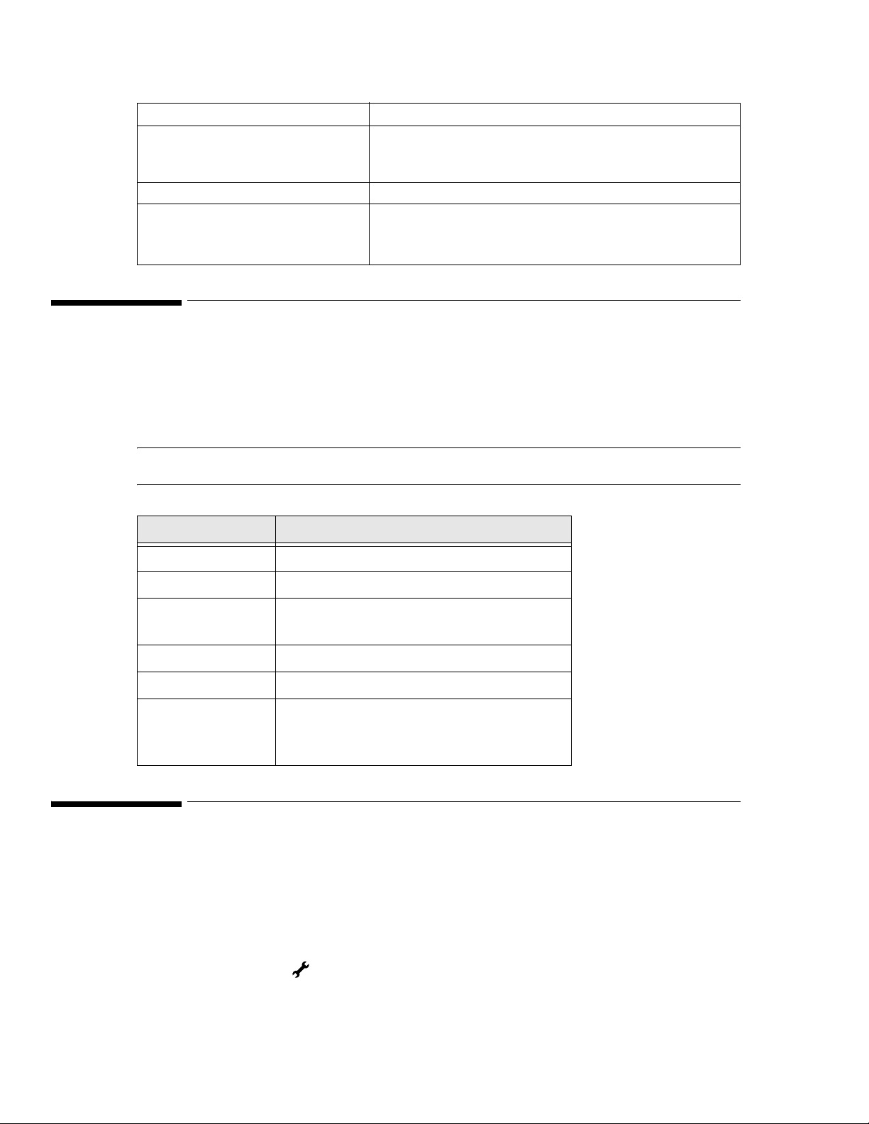
Accessing the System Menu
Use the System Menu to configure the monitor, view system information, shut down the monitor,
and access the System Admin Menu. For more information about using the System Menu to
configure the monitor, see the Instructions for Use or the Installation and Configuration Guide
provided with your monitor.
To access the Sy
stem Menu:
S(1):F/X1/X2
S(2): F/X1
• Select the System button.
The Sy
stem Menu appears.
Performance Verification Testing
3-4 SureSigns VS4 Service Guide
Page 25
Accessing the System Admin Menu
System Menu
Recorder Speed:
Waveform Print:
Date Format:
Serial Number:
Main Screen
25.0 mm/s
Hardware ID:
Software Version:
Configuration:
LAN MAC Address:
LAN IP Address:
Language:
USL0000001
6 - 00 - A7
A.04.52
VS4 SpO2-P Temp-T NBP-P
00-09-FB-13-4B-3C
0.0.0.0
English
Display Time:
20 seconds
Yes
Default Patient Type:
Recorder Wireless CO2-S
USL0000001
Monitor Name:
mm/dd/yyyy
Adult
System Admin
Brightness
Lock Touch Screen
Shutdown
WLAN MAC Address:
WLAN IP Address:
00-17-23-A1-84-B2
0.0.0.0
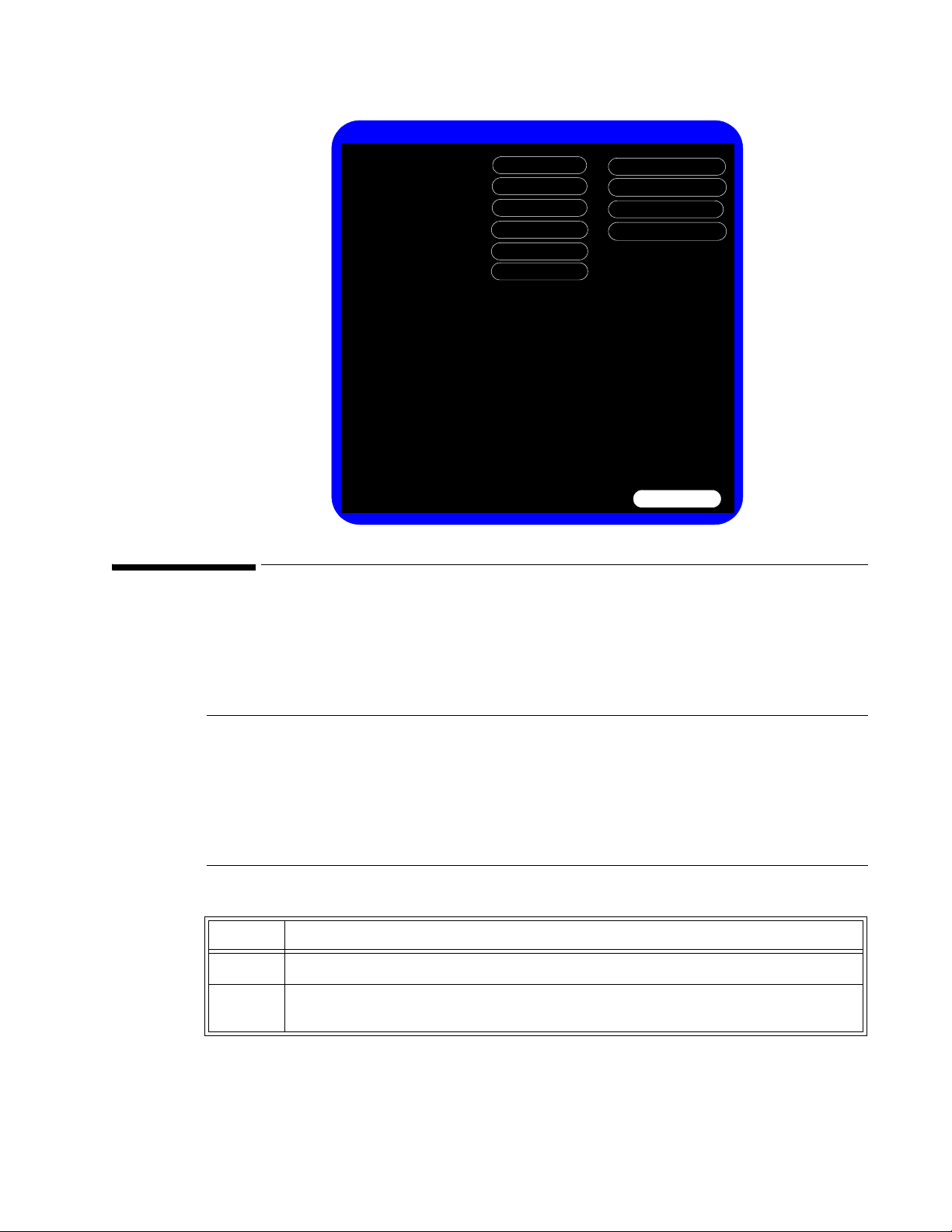
Accessing the System Admin Menu
You can use the System Admin Menu to configure password-protected functions of the monitor,
including Demo Mode, system diagnostics, and upgrading the software. For more information
about using the System Admin Menu to configure the monitor, see the Installation and
Configuration Guide provided with your monitor.
Notes
•The System Admin Menu is password-protected, and should only be accessed by
qualified service personnel.
• The procedures in this guide use the default Administrator password, 215. To improve
the security of the monitor settings, you can change the administrator password after
you install the monitor. For more information about changing the password, see the
Installation and Configuration Guide provided with your monitor.
To access the System Admin Menu:
Step
1 In the System Menu, select the System Admin button.
2 In the window that appears, enter the Administrator password, 215, or the password
defined by your institution and select OK.
Performance Verification Testing
SureSigns VS4 Service Guide 3-5
Page 26
Accessing the System Admin Menu
System Admin Menu
Language:
English
Diagnostics
Return
Default Initial NBP Inflation Pressure:
Adult:
Auto Suspend:
Neonate:
Pediatric:
Demo Mode
100160 140
Upgrade Software
Export Settings
Import Settings
Off
Default NBP Interval:
Default Save Measurements to Record:
Default Blue Probe Site:
2 minutes
Auto Save Patient Record:
1 minute
Patient ID Settings
Align Interval to Clock:
No
QuickCapture
Data Export
Oral
QuickAlerts
Date/Time Settings
Large Battery Icon
On
Security
QuickCheck
QuickNBP
LAN
Wireless
Line Frequency:
60 Hz
Default Alarm Settings
Dashboard
Masimo Pulse Smart Tone:
Off
Masimo RRa Freshness Timeout:
15 Minutes
Step
3 Select OK.
The System Admin Menu opens.
Note — Masimo settings appear only if the Masimo SpO
module is installed.
2
Caution
The System Admin Menu remains unlocked for 1 minute after you close it. This
allows you to open the menu again without having to re-enter the password. Do
not leave the monitor unattended during the unlock time.
System Admin Menu Options
The following table describes the System Admin Menu options that are explained in this guide. All
other options on the menu are explained in the Installation and Configuration Guide and the
Network Configuration Guide provided with your monitor.
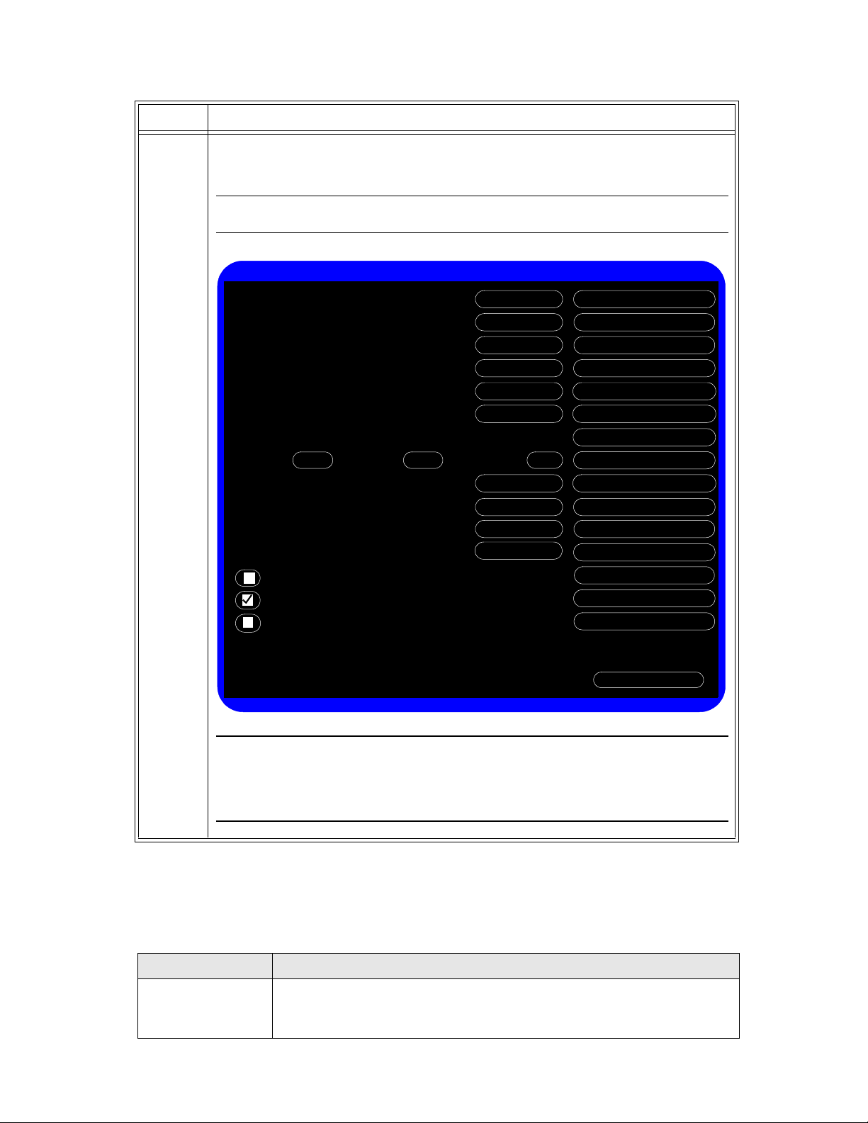
Option Description
Demo Mode Demo Mode allows the monitor to be demonstrated without actually
Performance Verification Testing
3-6 SureSigns VS4 Service Guide
monitoring parameters.
For more information, see “Enabling Demo Mode” on page 3-7.
Page 27
Option Description
Diagnostics Opens the System Diagnostics menu. Monitoring is suspended while this
Upgrade Software Opens the Upgrade Software menu.
Enabling Demo Mode
Accessing the System Admin Menu
menu is open.
Note — This button is unavailable when the monitor is running in Demo
mode.
For more information, see “Performing Verification Tests” on page 3-11.
For more information, see “Upgrading the Software” on page 3-8.
Warning Do not connect a patient to a monitor running in Demo mode. Values represented in Demo mode
do not represent measurements from a patient connected to the monitor, and may lead to
incorrect diagnoses.
Demo mode is used for demonstrating the monitor without monitoring parameters. Demo mode
simulates all patient parameters and generates alarms when alarm settings are exceeded.
By default, the check box is cleared.
Caution Entering Demo mode clears the patient data.
Note — You cannot access the System Diagnostics menu when the monitor is in Demo mode.
To put the monitor in Demo mode:
Step
1 Open the System Admin Menu. See “Accessing the System Admin Menu” on
page 3-5.
2 Select the Demo Mode check box.
3 Select the Return button.
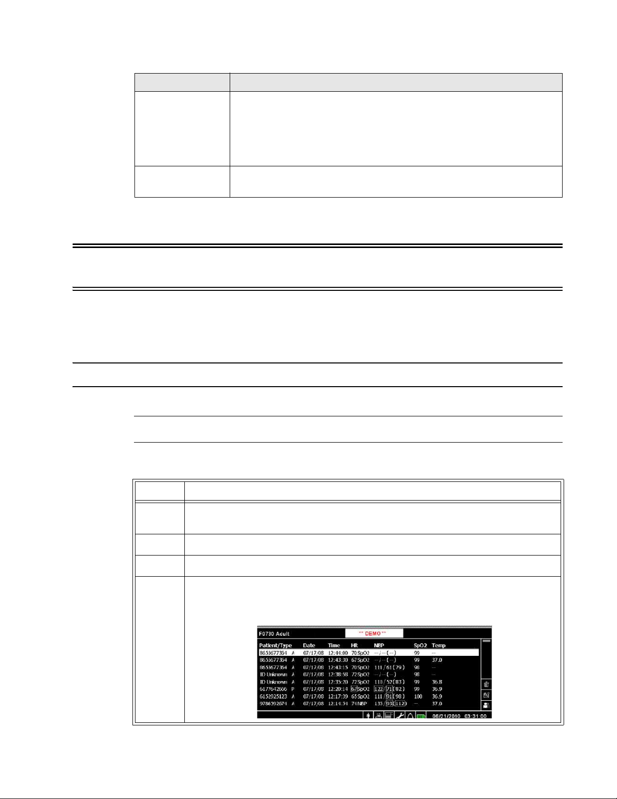
4 Select Yes.
The monitor enters Demo mode and clears all patient data and ** DEMO ** is
displayed.
Performance Verification Testing
SureSigns VS4 Service Guide 3-7
Page 28

Upgrading the Software
Step
5 To exit Demo mode, press the On/Standby key to turn off the monitor.
The monitor clears all simulated patient data.
Upgrading the Software
Use the following procedure to upgrade the system software with a USB flash drive. When you
upgrade the software, the monitor saves all of the system settings, including the System Admin
Menu settings, the Error log, and the patient list.
Before you place an upgraded monitor back into se
establishes a protocol to train users about any changes in the functionality of the monitor resulting
from the software upgrade.
rvice, Philips recommends that your facility
Registering for Software Upgrades from Philips InCenter
You can download a software upgrade from Philips InCenter, which requires an active registration
and password.
Before you register, obtain the serial number of the monitor you plan to include in your registration.
The serial number is located on the product identification label on the rear of case of the monitor.
To register:
Step
1 Access the Philips InCenter website at incenter.medical.philips.com.
2 Click Ne
3 Under Software Updates, click
registration.
The Sure
4 Enter your personal information and answer the questions, and then click Submit.
After your information is processed, an ema
sent to the email address you entered. It may take 24 to 48 hours to receive the
email.
ed Help?.
Click here for SureSigns patient monitor account
Signs InCenter Registration Form appears.
il with temporary login information is
Note — Philips recommends using a SanDisk
upgrades.
Caution Before you upgrade the software, you can back up the system settings by exporting the current
configuration settings or by recording them on the worksheets. For worksheets and more
information, see the Installation and Configuration Guide provided with your monitor.
Do not downgrade the software to an earlier version, because it may cause hardware
incompatibility and loss of system settings and patient records. The current software version is
displayed on the start-up screen and the System Menu. For more information, see “Viewing
System Information” on page 4-1.
When you upgrade the software:
Performance Verification Testing
3-8 SureSigns VS4 Service Guide
®
or Kingston® USB flash drive for software
Page 29

Upgrading the Software
• Charge the battery before upgrading the software.
• Never perform a software upgrade with the monitor connected to a patient.
• Disconnect any USB peripherals.
• Do not upgrade software through a USB hub.
• If the USB port has a clamp in place, you may need to remove the clamp to ensure that the
USB flash drive can be inserted completely into the USB port.
After the upgrade starts:
• Do not unplug the monitor.
• Do not remove the USB flash drive.
• Do not press any keys.
If the upgrade is inadvertently interrupted and the main board data is lost, replace the main
board. For more information, see “Removing the Main Board” on page 5-33.
To perform a software upgrade:
Step
1 Connect the monitor to AC power and power up the monitor.
Note — Your monitor must be connected to AC power and have a fully charged
battery before upgrading the software.
2 Insert the USB flash drive with the software upgrade into the USB port on the
back of the monitor.
Note — The software upgrade folder must be located in the top directory of the
USB flash drive.
3 Open the System Admin Menu. See “Accessing the System Admin Menu” on
page 3-5.
Performance Verification Testing
SureSigns VS4 Service Guide 3-9
Page 30
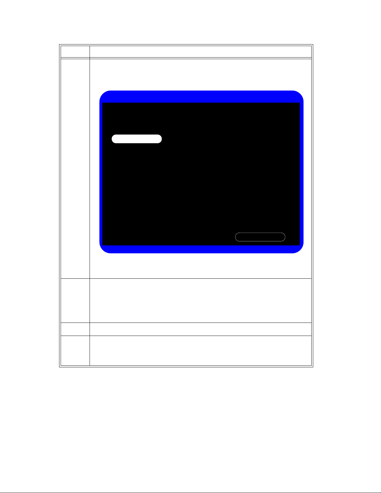
Upgrading the Software
Upgrade Software
Current Version:
Return
Upgrade
A.05.24
A.05.25
New Version:
WARNING: Battery should be charged before upgrading software. Do no unplug the
monitor, remove the USB flash drive, or press any keys after the upgrade process begins.
Any user interaction during the upgrade may cause the upgrade to fail and adversely
affect monitor performance.
Step
4 Select the Upgrade Software button.
The monitor searches for a valid software image on the USB flash drive, and then
displays the software image information in the Upgrade Software window.
If the monitor cannot find a valid software image, the screen returns to the
System Admin Menu.
5 Select the Upgrade Software button to start the upgrade.
The Upgrade in Progress indicator increments while the upgrade is in progress.
When the upgrade is complete, the Checking Memory CRC and Upgrade
Successful messages appear.
After the software upgrade, the monitor automatically shuts down and restarts.
6 Remove the USB flash drive.
7 Before placing the monitor back in service, perform the following:
• Power-on self test. See “Power-On Self Test” on page 3-13.
• Verify that your system settings are as expected.
Performance Verification Testing
3-10 SureSigns VS4 Service Guide
Page 31

Performing Verification Tests
System Diagnostics
Monitoring Suspended
NBP Cycle Count: 44
LCD Usage Hours: 23.1
Return
Error Log
Self Test
Recorder Test
Battery Info
Keys Test
Display Test
Audio Test
LED Test
Errors: 0
Touch Screen Calibration
Network Test
Maintenance >>
Some of the verification tests require using the System Diagnostics menu or the Maintenance
options. When you open the System Diagnostics menu, monitoring is suspended and
measurements stop.
Notes
• The Charging LED does not show battery status while the System Diagnostics menu is
open.
•The System Diagnostics menu is not available when the monitor is in Demo mode.
Accessing the System Diagnostics Menu
Use the System Diagnostics Menu to track component usage hours and perform the system
diagnostic and verification tests.
Performing Verification Tests
Note — You cannot access the System Diagnostics menu when the monitor is in Demo mode.
To access the System Diagnostics menu:
Step
1 Open the System Admin Menu. See “Accessing the System Admin Menu” on
page 3-5.
2 Select the Diagnostics button.
The System Diagnostics menu appears.
Performance Verification Testing
SureSigns VS4 Service Guide 3-11
Page 32

Performing Verification Tests
System Diagnostics
Monitoring Suspended
NBP Cycle Count: 44
LCD Usage Hours: 23.1
Return
Error Log
Self Test
Recorder Test
Battery Info
Keys Test
Display Test
Audio Test
LED Test
Errors: 0
Touch Screen Calibration
Network Test
Configuration
Reset
Reset
Reset
Reset S/N
NBP Test
Clear Data
Step
3 To access the options under the Maintenance >> button, see “Accessing
Maintenance Options” on page 3-12.
Accessing Maintenance Options
You must enter an additional password to access the Maintenance options. Only trained biomedical
engineers or support personnel should access the Maintenance options.
To access the Maintenance options in the System Diagnostics menu:
Step
1 Open the System
Diagnostics menu. See “Accessing the System Diagnostics Menu”
on page 3-11.
2 Select the Maintenance >> but
ton.
3 In the window that appears, enter the password, 129.
The Sy
stem Diagnostics menu displays additional options.
Note — Masimo SpO
and CO2 settings appear only if those modules are
2
installed.
Performance Verification Testing
3-12 SureSigns VS4 Service Guide
Page 33

Visual Test
To perform the visual test:
Visual Test
Step
1 Inspect the system for obvious signs of dama
breakage.
2 Check all external cables and accessories for
wrong connections.
3 Ensure that all markings a
If the labels on the rear case are not legible, replace the rear case. If the serial
number label is not legible, contact the Philips Customer Care Center or your local
Philips representative to return the monitor for label replacement.
4 Check for any obstructions to mechanical parts.
The expected test result is that the system
obstruction.
Note — Philips employees record this value as V:P or V:F.
Power-On Self Test
To perform the power-on self test:
Step
1 Connect the monitor to an AC power source.
ge; for example, cracks, cuts, or
damage; for example, cuts, kinks,
nd labeling are legible.
has no obvious signs of damage or
2 Press the
3 Make sure that the monitor powers up successfully as
sequence:
• The screen displays color bars for about five seconds.
• The LCD turns off for three seconds,
• The Philips screen appears for one second, and a startup tone
• The main screen appears.
The expected result is that the monitor starts up and displays the main screen. For
de
Power Sequences” on page 4-2.
If the LEDs do not function as expected, see “Power Problems” on page 4-4.
If the display does not function as expected, se
“Display Problems” on page 4-6.
If you do not hear a startup tone, or the monitor displays the Speaker Malfunc error
message, see “Error Codes” on page 4-13.
On/Standby key to power up the monitor.
and the charging LED lights.
tailed information about the start-up and power sequences, see “Start-up and
e “Power Problems” on page 4-4 or
Note — Philips employees record this value as PO:P or PO:F.
Performance Verification Testing
SureSigns VS4 Service Guide 3-13
described in the following
sounds.
Page 34

Alarms Test
Alarms Test
The following test allows you to verify that the visual and audio alarms are working.
To perform this test, you need an NBP cuff and hose.
To test the alarms:
Step
1 With the monitor turned on, make sure that all alarms are enabled (the monitor is not
in Audio Pause or Audio Off mode).
2 Make sure the NBP alarm is enabled (the crossed bell icon does not appear in the
NBP numeric pane).
3 Connect the NBP hose to the NBP input connector, but do not place the cuff on your
arm.
4 Press the NBP key on the front panel.
5 Wait for the NBP module to cycle and check that an NBP error message appears and
an alarm tone sounds.
SpO2 Test
6 If you do not get the results in step 5, see “NBP Problems” on page 4-6.
The following procedure tests the performance of the SpO2 measurement and alarm.
To perform this test, you need an adult SpO2 sensor.
To perform the SpO2 test:
Step
1 Connect an adult SpO
red LED in the sensor is lit.
2 Connect the other end of the sensor to your finger.
3 Verify that the SpO
not, try the test again with a patient simulator.
4 If you still do not get the results in step 3, see “SpO2 Measurement Problems”
page 4-9.
sensor to the SpO2 connector on the monitor. Ensure that the
2
value displayed on the monitor is between 95% and 100%. If it is
2
on
Caution A functional tester cannot be used to assess the accuracy of a pulse oximeter monitor.
3-14 SureSigns VS4 Service Guide
However, if there is independent demonstration that a particular calibration curve is accurate
for the combination of a pulse oximeter monitor and a pulse oximeter sensor, then a functional
tester can measure the contribution of a monitor to the total error of a monitor/sensor system.
The functional tester can then measure how accurately a particular pulse oximeter monitor is
reproducing that calibration curve.
Performance Verification Testing
Page 35

CO2 Calibration Test
This test checks the calibration of the Microstream CO2 gas measurement. The CO2 calibration test
is required after the first 1,200 hours of use or one year, whichever comes sooner. After the first
calibration, calibrate after 4,000 hours of continuous use or every year, whichever comes sooner.
In addition, perform the calibration tests when the instrument is repaired or when parts are
replaced.
CO
Calibration Test
2
Note — Replace the CO
Caution If the initial calibration is performed before 720 hours of use, the module resets to require the
next calibration after 1,200 hours instead of after 4,000 hours.
This test uses calibration equipment that you can order. Refer to the documentation accompanying
the calibration equipment for more details.
module after 20,000 hours of use.
2
Warning A monitor that is not calibrated at the recommended intervals may provide inaccurate results.
Dispose of empty or partially empty calibration gas containers in accordance with the
manufacturer’s instructions and local regulations.
Required Test Equipment
• Electronic flowmeter, M1026-60144
• Gas calibration equipment:
– Cal 1 gas 15210-64010 (5% CO2)
– Cal gas flow regulator M2267A
– Cal tube 13907A
CO2 Gas Measurement Calibration Check
To check the calibration of the CO2 gas measurement:
Step
1 Ensure that the CO2 module is not in Standby mode (when the monitor is in Display
Waveform mode, Standby is displayed in the CO2 waveform pane).
If necessary, turn on the CO2 module by opening the CO2 Menu and setting
Hardware: to On.
CO2
2 Open the Maintenance options in the System Diagnostics menu. See “Accessing
Maintenance Options” on page 3-12.
Performance Verification Testing
SureSigns VS4 Service Guide 3-15
Page 36

CO2 Calibration Test
Last Calibration Date:
CO2 Usage Time:
Hours to Calibration:
Hours to Service:
757
3243
19,243
CO2 Test
Return
CO2 (mmHg):
Start Calibration Check
Stop Calibration Check
Start Calibration
Stop Calibration
2009/5/18 18:21
1035
18965
Last Calibration Date:
CO2 Usage Time:
Hours to Calibration:
Hours to Service:
0
Firmware Version:
Hardware Version:
5.01
2.31
3 Select the CO2 Test button.
The CO2 Test menu appears.
4 Connect one end of the sampling line to the CO2 inlet on the monitor and leave the
5 In the CO2 Test menu, select Start Calibration Check.
6 Connect the other end of the sampling line to the gas controller equipment inlet with
7 Open the valve on the gas controller equipment to allow 5% CO2 gas to flow into the
8 Select OK in the confirmation window to begin checking the calibration.
Calibrating the CO2 Module
9 If the module is not in calibration, an error message appears. Calibrate the module.
10 Turn off the flow of gas and select Return in the CO2 Test menu. Press the wheel to
other end unconnected.
A message to connect the gas to the CO2 module appears.
a 5% gas concentration.
monitor.
Note — The calibration check can take up to one minute to complete. The monitor
checks the calibration and when the calibration check completes, the CO2 Test
window displays a message. For example:
CO2 calibration check successful. CO2 rate: 5.1.
“Calibrating the CO2 Module” on page 3-16.
See
exit the test.
Caution Because the monitor uses the current date and time as the calibration date and time, ensure
3-16 SureSigns VS4 Service Guide
that the system date and time is set correctly.
Performance Verification Testing
Page 37

NBP Test
Note — The monitor always displays the CO
menu.
To calibrate the CO2 module:
module’s operating (usage) time in the CO2 Test
2
Note — Do not perform the initial calibration before 720 hours of use. If the initial calibration is
performed before 720 hours of use, the module will reset, and then require its next
calibration after 1,200 hours, instead of after 4,000 hours.
Step
1 Connect one end of the sampling line (if not already connected) to the CO2 inlet on
the monitor and leave the other end unconnected.
2 In the CO2 Test menu, select Start Calibration.
A confirmation window appears telling you to
3 Connect the other end of the sampling line to the
a 5% gas concentration.
4 Open the valve on the gas controller equipment to allow 5% CO2 gas to flow into the
monitor.
connect the gas to the CO2 module.
gas controller equipment inlet with
NBP Test
5 Select OK i
The monitor begins calibrating the CO
when complete.
n the confirmation window to begin calibrating.
module and displays the calibration value
2
Note — The calibration process can take up to one minute to complete.
6 Turn off the flow of
exit the test.
7 If the calibration is successful, the Last Calibration Date and Hours to Calibration in
the CO2 Test menu reset. To check this, re-open the CO2 Test menu.
8 If the module is not able to calibrate itself, an error
CO
module. See “Removing the CO2 Module” on page 5-15.
2
These tests check the performance of the non-invasive blood pressure measurement:
• NBP accuracy
• NBP calibration procedure (if required)
• NBP pneumatic leakage
To perform these tests, you need:
gas and select Return in the CO2 Test menu. Press the wheel to
message appears. Replace the
• A reference manometer (includes hand pump and valve), accuracy 0.2% of reading
• An expansion chamber (volume 250 ml
• Appropriate tubing
10%)
Performance Verification Testing
SureSigns VS4 Service Guide 3-17
Page 38

NBP Test
SureSigns VM Patient Monitor
Expansion chamber MonitorManometer
NBP Accuracy
Note — Philips recommends that you do not test NBP accuracy with a simulator.
To test the NBP accuracy:
Step
1 Connect the manometer and the pump with tubing to the NBP connector on the
monitor.
2 Connect the tubing to the expansion chamber (250 ml cylinder).
3 Open the Maintenance options in the System Diagnostics menu. See “Accessing
Maintenance Options” on page 3-12.
Performance Verification Testing
3-18 SureSigns VS4 Service Guide
Page 39

Step
NBP Test
Pressure (mmHg):
Return
Start Static Pressure Test
NBP Calibration
Firmware version: 0.33
4 Select NBP Test.
The NBP Test menu appears.
NBP Test
10 Select the Stop Static Pressure Test button to stop the test.
5 Select the Start Static Pressure Test button to start the test.
6 Squeeze the manometer pump and apply a pressure of 280 mmHg.
7 Wait 10 seconds for the pressure to stabilize. Note the pressure displayed in the NBP
Test menu. The value should be 280 mmHg 3 mmHg.
Note — Philips employees record this value as X1.
8 Squeeze the manometer pump to apply a pressure of 150 mmHg to the monitor.
9 Wait 10 seconds for the pressure to stabilize. Note the pressure displayed in the NBP
Test menu. The value should be 150
mmHg 3 mmHg.
Note — Philips employees record this value as X2.
11 If the difference between the manometer and displayed values is greater than
mmHg, calibrate the monitor (see “NBP Calibration Procedure” on page 3-20).
3
If the results are as expected, proceed to the “Pneumatic Leakage Test” on
page 3-21.
Performance Verification Testing
SureSigns VS4 Service Guide 3-19
Page 40

NBP Test
NBP Calibration
Set Pressure Value:
Start
CAL P1
Stop
220.0
Return
NBP Calibration Procedure
To calibrate the NBP module:
Step
1 In the NBP Test menu, Select NBP Calibration.
Note — To stop the calibration process at any time, select Stop.
The NBP Calibration menu appears.
2 Select the Start button to begin calibration.
3 Wait until the message, Ready for calibration at first pressure point..., appears.
4 Select the Set Pressure Value field, and then select the value to match that
5 Select CAL Point to save the calibration point.
6 Wait until the message, NBP calibration successful, appears.
7 Select the Return button to exit the test.
8 To verify the calibration, check the accuracy of the NBP. See “NBP Accuracy” on
Performance Verification Testing
3-20 SureSigns VS4 Service Guide
Note — If you are using a manual manometer, close the valve before continuing.
The monitor inflates the expansion chamber and displays the message, Starting NBP
Calibration...
displayed on the manometer.
If the test fails for any reason, select the Stop button to stop the test.
page 3-18.
Page 41

Step
9 If you do not get the expected results after several tries, see
Chapter 4, “Troubleshooting.”
Pneumatic Leakage Test
To check the pneumatic system and valve:
Step
Predictive Temperature Test
1 In the NBP Te
2 Squeeze the manometer pump to apply a pressure of 280 mmHg.
3 Wait 10 seconds for the pressure
Test menu.
st menu, select the Start Static Pressure Test button.
to stabilize. Note the pressure value in the NBP
Note — Philips employees record this value as P1.
4 Wait 60 seconds for the pressure to stabilize. N
Test menu.
ote the pressure value in the NBP
Note — Philips employees record this value as P2.
5 Calculate and document the leakage test value.
less than or equal to 6 mmHg.
The leakage test value should be
Note — Philips employees record this value as X3 (where X3 = P1 - P2).
6 Select the Stop
7 If the leakage test value exceeds 6 mmHg, check
then test again. If the test still fails, check the pneumatic tubing inside the monitor.
8 If you cannot eliminate the leak, see Chapter 4, “Troubleshooting.”
Static Pressure Test to stop the process.
the test setup cuff and tubing, and
Predictive Temperature Test
The following procedure uses a fixed temperature value to check the performance of the predictive
temperature module.
To perform this test, you need:
• A SureSigns temperature probe
• A SureSigns Temperature Calibration Key (part # 4535 640 33691)
To test the performance of the temperature measurement:
Step
1 Connect the temperature probe to the monitor.
2 Open the Te
mperature Menu and select Monitored mode.
Performance Verification Testing
SureSigns VS4 Service Guide 3-21
Page 42

Tympanic Temperature Test
Step
3 Remove the temperature probe and the probe well and disconnect the temperature
4 Connect the SureSigns temperature calibration key to the temperature module.
5 Replace the temperature probe and the probe well.
6 Remove the temperature probe from the probe well.
7 Wait for the monitor to display the static temperature value.
8 Check that the displayed temperature reads 36.3°C ± 0.1°C (97.3°F ± 0.2°F).
9 If the value is not within tolerance, see “Temperature Measurement Problems” on
probe connector from the monitor.
Note — A temperature probe error may occur and an alarm may sound.
Note — If a temperature probe error was generated, the alarm stops.
page 4-8.
Tympanic Temperature Test
To verify the performance of the tympanic temperature module, you must do one of the following:
• Send the monitor to Philips for calibration. Contact the Philips Customer Care Center or your
local Philips representative
• Purchase a Covidien calibration device, part number 303079. See the Covidien web site for
ordering information (www.covidien.com).
Note — The battery compartment in the tympanic temperature probe is not functional.
Temporal Temperature Test
To verify the performance of the temporal temperature module, you must do one of the following:
• Send the monitor to Philips for testing. Contact the Philips Customer Care Center or your local
Philips representative.
• Purchase an Exergen calibration verification kit. See the Exergen web site for ordering
information (www.exergen.com).
Safety Tests
Use the following safety test procedures to verify safe service of the monitor. The setups and
the acceptable ranges of values used for these tests are derived from local and international
standards, but may not be equivalent. These tests are not a substitute for local safety testing
where it is required for an installation or a service event. If you use the Metron Safety tester,
perform the tests in accordance with your local regulations. For example, in Europe, use
IEC 60601-1 and in the United States, use UL 60601-1. The Metron Report should print results
with the names listed below, together with other data.
Performance Verification Testing
3-22 SureSigns VS4 Service Guide
Page 43

Note — Safety tests meet the standards of, and are performed in accordance with IEC 60601-1,
(*) Not present in Class 2.
(**) Can be multiple different connections to different equipment at same time.
PE
Instrument under test
Applied part
(*)
S4
N (L)
S1
S2
L (N)
Signal par ts
in- and/or
output
MD
Medical electrical system
Signal parts
in- and/or
output
Other
Instrument
(**)
Medical Electrical Equipment
(**) Can be m ultiple different connections to different equipment at same time.
PE
Instrument under test
Applied part
S4
N (L)
S1
S2
L (N)
Signal parts
in- and/or
output
MD
Medical electrical system
Signal parts
in- and/or
output
Other
Ins tru m e nt
(**)
Medical Electrical Equipment
Clause 19 (EN60601-1). The SureSigns vital signs monitors have been classified as Class I
equipment.
To perform these tests, you need a multimeter.
The monitor safety tests include:
• Enclosure leakage
• Ground integrity
• Patient leakage current with mains voltage
Enclosure Leakage
S(1) Part 1: Enclosure Leakage Current - NC (normal condition)
Safety Tests
Expected Test Results
Normal condition maximum leakage current x1 100A.
This measures leakage current of exposed metal parts of Instrument under Test (IUT) and between
parts of the system within the patient environment; normal and reversed polarity using S2.
Safety test according IEC 60601-1 / UL 60601-1.
S(1) Part 2: Enclosure Leakage Current - Single Fault (open earth)
Expected Test Results
Performance Verification Testing
SureSigns VS4 Service Guide 3-23
Page 44

Safety Tests
50 Hz 25 A or 1.5 Ir
Ohm
L (N)
N (L)
PE
Instrument under test
Applied part
Insulating pad
Ri
6V
(*)
(*) If equipotential connection present : measure also
with yellow/green E.P. conductor connected.
Insulating pad
R
S6
(*) Not present in Class 2
N (L)
Instrument under test
Applied part
PE
S1
S2
L (N)
S4 (*)
Signal part
in- and/or
output
L (N)
N (L)
S5
MD
Single Fault maximum leakage current x2 500A (IEC 60601-1).
300A (UL 60601-1)
This measures leakage current of exposed metal parts of Instrument under Test (IUT) with
Protective Earth (PE) open circuit (S4 = open) and between parts of the system within the patient
environment; normal and reversed polarity using S2.
Ground Integrity
S(2) Protective Earth Continuity
Expected Test Results
With mains cable, maximum impedance x 100 mOhms (IEC 60601-1 and UL 60601-1).
This measures impedance of Protective Earth (PE) terminal to all exposed metal parts of Instrument
under Test (IUT), which are for safety reasons connected to the Protective Earth (PE). Test current
25 Amp applied for 5 to 10 seconds.
Patient Leakage Current With Mains Voltage
S(3) Patient Leakage current - Single Fault Condition (S.F.C.) mains on applied part
Expected Test Results
Maximum leakage current, x 50A @ 250V (IEC60601-1 and UL 60601-1).
3-24 SureSigns VS4 Service Guide
Measures patient leakage current from applied part to earth caused by external main voltage on
applied part with switch S5 open and closed. Each polarity combination possible is tested using S2
and S6. This test is applicable for every measurement input.
Performance Verification Testing
Page 45

Nurse Call Relay Test
Tip
Ring
Sleeve
Condition
Phone Jack Connector Tip
(Relay Normally Open)
Phone Jack Connector
Ring (Relay Normally
Closed)
Alarm Closed Open
No alarm Open Closed
If your facility uses the nurse call function on the monitor, perform the following procedure to test
the nurse call alarm output relay.
Nurse Call Relay Test
The nurse call alarm output is a phone jack connector that is
normally open relay operation.
The nurse call connector jack has three contacts that connect with those on a phono connector as
shown in the following illustration.
• Tip — Relay normally open, closed for alarm
• Ring — Relay normally closed, open for alarm
• Sleeve — Common
To perform this test, you need:
• A patient simulator
• An ohmmeter
• A phono connector
To perform the nurse call relay test:
capable of both normally closed and
Step
1 Plug the phono connector into the Nurse Call
2 Use the ohmmeter and patient simulator to
3 If the nurse call function does not work as expected, see
Chapter 4, “Troubleshooting.”
connector on the back of the monitor.
verify relay operation as follows:
Performance Verification Testing
SureSigns VS4 Service Guide 3-25
Page 46

Calibrating the Touch Screen
Calibrating the Touch Screen
When you replace the LCD, you must calibrate the touch screen after reassembly.
To calibrate the touch screen:
Step
1 Open the System Diagnostics menu. See “Accessing the System Diagnostics Menu”
on page 3-11.
2 Select the Touch Screen Calibration button.
Notes:
• You cannot enter the calibration mode with the navigation wheel, you must
select the Touch Screen Calibration button.
• You cannot exit the test until it is completed.
3 Select the To
The calibration screen appears.
4 Touch and hold the center of the target cross hair
moves to another position.
Caution
Use your finger to perform the test. Do not use a sharp object that could scratch
the screen.
5 For remaining target cross hairs, repeat step 4 until the calibration is complete and
the following message appears:
New calibration settings have been measured.
Press the navigation wheel to accept the new settings.
6 Press the wheel to save the calibration
7 Touch the screen anywhere to end the test.
uch Screen Calibration button again.
that appears until the target
settings.
Performance Verification Testing
3-26 SureSigns VS4 Service Guide
Page 47

Use the information in this chapter to diagnose and correct monitor problems. This chapter
describes how to troubleshoot a monitor that is not operating correctly. Chapter 5, “Repairing
the Monitor,” describes how to perform the recommended repairs.
You can repair the monitor in either of two ways:
• Bench repair, where you return the monitor to a Philips authorized service center for repair.
• Spare parts, where you order replacement parts and you repair the monitor.
The tools required to repair the monitor are listed in “Tools Required for Service” on page 5-2. If
you open the case for a repair, you then must perform specific tests after reassembly. For
detailed information about these tests, see
The Philips Parts Center stocks board level assemblies and mechanical parts.
Chapter 6, “Replacement Parts and Assembly Drawings,” lists these parts and assemblies.
Service notes announce the availability of additional spare parts.
When You Cannot Correct a Problem
The information in this chapter is intended to help you resolve most problems that may occur
with your monitor. If you still cannot isolate a problem after using the information in this chapter,
call the Philips Customer Care Center or your local representative.
4
Troubleshooting
Chapter 3, “Performance Verification Testing.”
Note — If you have created a custom password for your institution, you must change the
password to the Philips default (215) before you return the monitor for any reason.
Viewing System Information
Before you troubleshoot the monitor, identify important information about the monitor, such as
the hardware version and the software version, which are displayed in the System Menu.
To view t h e System Menu:
• Select the System button.
The System Menu appears.
Diagnosing a Problem
Before you begin to troubleshoot a problem or open the monitor for repair, check the following
basics:
1. Is the power switch turned on?
2. Is the battery adequately charged?
3. Is the AC power cord connected to the monitor and plugged into a functional AC outlet?
4. Is the monitor's display functioning?
5. Are the LEDs on the front of the monitor lit as you expect?
SureSigns VS4 Service Guide 4-1
Troubleshooting
Page 48

Start-up and Power Sequences
Note — It may take several seconds for the AC Power LED to light or turn off after the AC power
cord has been connected or disconnected.
If the monitor is not receiving power:
1. Check “Start-up and Power Sequences” on page 4-2, and then follow the troubleshooting
steps in “Power Problems” on page 4-4.
2. If the monitor has no — or an incorrect — display, follow the troubleshooting steps in
“Display Problems” on page 4-5.
When the monitor has power and a functioning display, use the information in this chapter to
diagnose other monitor problems.
Start-up and Power Sequences
The following table describes the start-up and power on phases of the monitor and its
components. If the monitor does not behave as described in the following table, see
Problems” on page 4-5.
“Display
For the monitor to start correctly, it must be powered correctly and the +3.3V system board supply
voltage must be working properly as indicated by the lit LEDs on the front panel.
User Action Expected Result
Plug the AC power cord or insert
the battery (or both) into an
unpowered monitor.
Press the On/Standby key.
Press the On/Standby key when
the monitor (with AC and/or
battery) is off.
Software reset (system or user). The screen displays the color bar for about five seconds.
The screen displays the color bar for about five seconds.
The LCD is off and the Charging LED lights (when the
battery is available).
The Philips splash screen appears and a tone sounds.
The Date/Time Menu appears for a new time setting.
After you acknowledge the Date/Time Menu, the main
screen appears.
The screen displays the color bar for about five seconds.
The LCD is off and the Charging LED lights (when the
battery is available).
The Philips splash screen appears in one second and a
tone sounds.
The main screen appears.
The LCD turns off and the Charging LED lights (when the
battery is available).
The Philips splash screen appears in one second and a
tone sounds.
The main screen appears.
Plug AC power cord into a monitor
that is off (battery only).
Press the On/Standby key.
Troubleshooting
4-2 SureSigns VS4 Service Guide
The screen displays the color bar for about five seconds.
The LCD is off and the Charging LED lights (when the
battery is available).
The Philips splash screen appears and a tone sounds.
The New Patient Menu displays for new patient settings.
After the New Patient Menu is acknowledged, the main
screen appears.
Page 49

User Action Expected Result
Troubleshooting Tables
Press the On/Standby key when
the monitor is in Standby mode
(AC and/or battery).
Press the On/Standby key when
the monitor is on (AC and/or
battery).
Select Shutdown in the System
Menu.
Troubleshooting Tables
Use the following tables to diagnose and fix monitor problems. The tables describe a monitor
problem by symptom, list a possible cause, and suggest actions. Check the first possible cause
listed, and then perform the associated action to repair the problem. Perform all actions in the
order that they appear in a table.
Monitor problems are categorized as follows:
•Power
•Display
•Alarms
• Measurements, including:
–NBP
– Temperature
–SpO
•CO
• Navigation wheel, touch screen, and keys
•Recorder
•Nurse Call
•USB hub
•Security
2
2
A tone sounds. The New Patient Menu displays the new
patient setting.
After the New Patient Menu is acknowledged, the main
screen appears.
The Philips splash screen appears and the LCD turns off.
The Philips splash screen appears and a tone sounds. The
LCD turns off.
Note — If using the following troubleshooting tables does not solve the problem, see “Running
System Diagnostics” on page 4-32.
SureSigns VS4 Service Guide 4-3
Troubleshooting
Page 50

Troubleshooting Tables
Power Problems
Symptom Possible Cause Action
The monitor turns on with
battery power, but does
not with AC power.
The monitor turns on with
C power, but does not
A
with battery power.
The monitor does not turn
with either AC or
on
battery power.
Only one of the Charging
LED col
The following message is
display
required
ors is displayed.
ed: Battery service
The power cord is unplugged. Ensure that the AC power cord is plugged into
an outlet.
The power cord is broken. Replace the AC power cord.
The fuse is blown. Replace the fuse. See “Removing a Fuse” on
page 5-6.
The power supply cable
malfunctioned.
The power supply
malfunctioned.
The AC power connector
malfunctioned.
The monitor keypad is worn. Replace the front panel. See “Removing the
The main board malfunctioned. Replace the main board. See “Removing the
The battery is not charged. Charge the battery. For more information, see
The battery or connector is
loose.
The battery does not have a
ction to the main board.
conne
The main board malfunctioned. Replace the main board. See “Removing the
The LCD, cables, battery, power
supply, or main board
malfunctioned.
The membrane switch
assembly malfunctioned.
The Max Error value exceeds
8%.
The Fu
ll Capacity value is one
half of the Design Capacity
value.
Replace the DC In cable. See “Removing the
Power Supply” on page 5-31.
Check output voltage on power supply. If you
do not mea
supply. See “Removing the Power Supply” on
page 5-31.
Replace the AC connector. See “Removing the
AC Power Connector” on page 5-39.
LCD Assembly” on page 5-44.
Main Board” on page 5-33.
“Maintaining the Battery” on page 2-2.
Reseat both the battery and battery cable.
Replace the battery board. See “Removing
the Battery Connector Board” on page 5-43.
Main Board” on page 5-33.
Follow the steps shown in the previous two
symptoms. If the problem is not resolved,
replace the LCD. See “Removing the LCD
Assembly” on page 5-44.
Replace the front panel. See “Separating the
Front and Rear Case Assemblies” on
page 5-16.
Recondition the battery. See “Reconditioning
the Battery” on page 2-4.
sure 15 V, replace the power
Troubleshooting
4-4 SureSigns VS4 Service Guide
Page 51

Troubleshooting Tables
Display Problems
Symptom Possible Cause Action
The power is on, but the monitor
screen is blank.
The monitor displays random or
ted graphics with a white
distor
background.
The monitor turns on and the
opening scr
starts, but then freezes.
een and/or color bar
The monitor is in Standby mode. Press the On/Standby key to end
Standby mode.
The connection with the backlight
faulty.
LCD is
The main board malfunctioned. Replace the main board. See
The LCD signal cable is not
attached correctly.
The LCD malfunctioned. Replace the LCD. See “Removing
The main board malfunctioned. Replace the main board. See
The main board malfunctioned. Replace the main board. See
Ensure that there is a proper
connection between the cable,
LCD, and main board.
“Removing the Main Board” on
page 5-33.
Open the monitor and reseat the
LCD signal cable. See “Removing
the LCD Assembly” on page 5-44.
the LCD Assembly” on page 5-44.
“Removing the Main Board” on
page 5-33.
“Removing the Main Board” on
page 5-33.
Alarm Problems
Symptom Possible Cause Action
A flashing red and white box
with the message AUDIO FAILED
appears on the screen.
The speaker malfunctioned. Clear the error message by
The connection to the speaker is a
ulty.
fa
The speaker is faulty. Replace the speaker. See
performing the speaker test or
clearing the error log. See “Testing
the Speaker” on page 4-36 or
“Clearing Patient Data” on
page 4-40.
Ensure that the connection to the
speaker is correct.
Clear the error message by
rforming the speaker test or
pe
clearing the error log. See “Testing
the Speaker” on page 4-36 or
“Clearing Patient Data” on
page 4-40.
“Removing the Fan and Speaker”
on page 5-25.
SureSigns VS4 Service Guide 4-5
Troubleshooting
Page 52

Troubleshooting Tables
Symptom Possible Cause Action
Audible alarms do not sound. The monitor is in Audio Pause
Confirm audio alarms are enabled.
mode or Audio Off mode.
The connection to the speaker is
faulty.
Ensure that the connection to the
speaker is correct.
The speaker malfunctioned. Replace the speaker. See
“Removing the Fan and Speaker”
on page 5-25.
The main board malfunctioned. Replace the main board. See
“Removing the Main Board” on
page 5-33.
The Auto Set Alarm Limits
button is unavailable.
Auto Set Alarm Limits function is
only available when the monitor is
in the Interval Setting Menu for
NBP, CO
, and SpO2.
2
Ensure that the monitor is in the
Interval Setting Menu for NBP, CO
and SpO2. See the Instructions for
Use provided with your monitor.
NBP Problems
Symptom Possible Cause Action
The NBP cuff does not inflate. The air tube or cuff is bent or
twisted.
Air leak in the air tube or cuff. Replace the cuff and ensure that
The NBP module malfunctioned. Replace the NBP pump module.
The NBP pump filter is blocked. Replace the NBP pump filter. See
The main board malfunctioned. Replace the main board. See
Straighten the tube or cuff.
there is no air leakage in the tube.
See “Removing the NBP Module”
on page 5-37.
“Removing the NBP Filter” on
page 5-38.
“Removing the Main Board” on
page 5-33.
,
2
Troubleshooting
4-6 SureSigns VS4 Service Guide
Page 53

Troubleshooting Tables
Symptom Possible Cause Action
NBP measurements are not
displayed.
Wrong cuff size, or incorrect cuff
placement.
Use proper cuff size, ensure proper
cuff placement.
Initial pressure setting is incorrect. Specify the correct initial pressure.
For more information, see the
Installation and Configuration
Guide provided with your monitor.
The air tube is bent or twisted or
there is air leakage in the air tube
or cuff.
Ensure that the tube is straight and
not kinked. Replace the cuff and
ensure that there is no air leakage
in tube.
External problem. Ensure that all external blood
pressure reading requirements are
met and that the patient is not
moving excessively. For more
information about measuring NBP,
see the Instructions for Use
provided with your monitor.
The NBP pump filter is blocked. Replace the NBP pump filter. See
“Removing the NBP Filter” on
page 5-38.
NBP module error. Replace the pump module or main
board. See “Removing the NBP
Module” on page 5-37 or
“Removing the Main Board” on
page 5-33.
NBP measurements are unreliable. Wrong cuff size, or incorrect cuff
placement.
Use proper cuff size and ensure
proper cuff placement.
Initial pressure setting is incorrect. Specify the correct initial pressure.
For more information, see the
Installation and Configuration
Guide provided with your monitor.
External problem. Ensure that all external blood
pressure reading requirements are
met and that the patient is not
moving excessively. For more
information about measuring NBP,
see the Instructions for Use
provided with your monitor.
The NBP module needs to be
calibrated.
Recalibrate the NBP module see
“NBP Calibration Procedure” on
page 3-20.
The NBP initial pressure too high. The cuff is too tight. Ensure the cuff is fastened
correctly.
The initial inflation pressure setting
is incorrect.
Specify the correct initial inflation
pressure. See the Installation and
Configuration Guide provided with
your monitor.
SureSigns VS4 Service Guide 4-7
Troubleshooting
Page 54

Troubleshooting Tables
Temperature Measurement Problems
Symptom Possible Cause Action
Temperature measurements are
not displayed.
Temperature measurements are
unreliable.
Tympanic temperature reading is
unusually high.
Tympanic temperature reading is
unusually low.
Temporal temperature
measurement is too high.
The probe is disconnected from
the monitor.
Ensure that the temperature probe
is connected and seated in the
probe well.
The probe is misplaced. Ensure that the probe is properly
placed in the measurement site.
The predictive temperature is over
range.
Ensure that the predictive
temperature reading is in the
range of 15°
See “Predictive Temperature Test”
on page 3-21.
The probe malfunctioned. Replace the probe.
Front end malfunction. Replace the front end board. See
“Removing the Front End
Assembly” on page 5-26.
The temperature module
malfunctioned.
Replace the temperature module.
See “Removing the Predictive
Temperature Module and Probe
Cover Holder” on page 5-6 or
“Removing the Tympanic
Temperature Module” on
page 5-11.
The main board malfunctioned. Replace the main board. See
“Removing the Main Board” on
page 5-33.
The probe malfunctioned. Replace the temperature probe.
The module is not calibrated. Calibrate the temperature module.
See “Predictive Temperature Test”
on page 3-21 or “Tympanic
Temperature Test” on page 3-22.
The front end malfunctioned. Replace the front end board. See
“Removing the Front End
Assembly” on page 5-26.
The temperature module
malfunctioned.
Replace the temperature module.
See “Removing the Predictive
Temperature Module and Probe
Cover Holder” on page 5-6 or
“Removing the Tympanic
Temperature Module” on
page 5-11.
The probe cover is faulty or
incorrectly attached.
Verify the tip of the probe cover is
not torn and that the probe is
inserted into the cover completely.
The probe, probe cover, or ear
canal is obstructed.
The measurement area is not
exposed.
Ensure the probe, probe cover, or
ear canal are free of obstructions.
Ensure the measurement area is
clear of obstruction.
– 45°C (59°F – 113°F).
Troubleshooting
4-8 SureSigns VS4 Service Guide
Page 55

Symptom Possible Cause Action
Temporal temperature
measurement is too low.
The measurement area is too
moist from perspiration.
Multiple measurements were
taken in rapid succession.
The probe moved in a curved
motion down the side of the face.
Ensure the skin where the
measurement is taken is dry.
Wait at least 30 seconds between
measurements.
Ensure correct motion of the
probe.
The lens is dirty. Clean the lens with an alcohol
pad.
Temporal temperature probe
displays ERR.
Temporal temperature probe
malfunctioned.
Replace the temporal temperature
probe.
SpO2 Measurement Problems
Symptom Possible Cause Action
SpO2 measurements are not
displayed.
measurements are
SpO
2
unreliable.
The SpO2 module is in the learning
phase.
The SpO
The SpO
sensor malfunctioned. Replace the SpO2 sensor.
2
board has a faulty
2
connection to the front end board.
Wait until the module finishes the
learning phase.
Ensure that all connectors to the
front end board are seated
correctly.
The SpO
board malfunctioned. Replace the SpO2 board. See
2
“Replacing the SpO2 Board” on
page 5-28.
The main board malfunctioned. Replace the main board. See
“Removing the Main Board” on
page 5-33.
External problem. For example,
excessive patient movement.
Ensure that all external SpO2
reading requirements are met and
that the patient is not moving
excessively. For more information
about taking SpO
the Instructions for Use provided
with your monitor.
Perfusion is low. Reset the SpO
“SpO2 Test” on page 3-14.
Troubleshooting Tables
readings, see
2
function. See
2
etCO2 Measurement Problems
Symptom Possible Cause Action
measurements are
CO
2
not displayed.
The CO2 module is initializing. Wait until initialization is complete.
The CO
sampling line is bent or
2
Ensure that the sampling line is straight.
twisted.
The CO
module malfunctioned. Replace the CO2 module. See “Removing the
2
CO2 Module” on page 5-15.
The main board malfunctioned. Replace the main board. See“Removing the
Main Board Assembly” on page 5-21.
SureSigns VS4 Service Guide 4-9
Troubleshooting
Page 56

Troubleshooting Tables
Symptom Possible Cause Action
CO2 measurements are
unreliable.
The CO2 sampling line is bent or
twisted.
A problem external to the
monitor occurred.
Ensure that the sampling line is straight.
Ensure that all external CO2 reading
requirements are met and that the patient is
not moving excessively.
The CO2 board is not calibrated. Calibrate the CO2 board. See “CO2
Calibration Test” on page 3-15.
Navigation Wheel, Touch Screen, and Key Problems
Symptom Possible Cause Action
The monitor does not respond to
the navigation wheel or front
panel keys.
Pressing a key does not access the
expected function. For example,
pressing the Print key initiates an
NBP measurement.
A key is collapsed, or doesn’t click
when pressed.
The monitor does not respond to
the touch screen.
The main board has a faulty
connection.
The front panel keypad or
navigation wheel is broken.
Ensure that all connectors to the
main board are seated correctly.
Replace the membrane switch or
navigation wheel. See “Removing
the LCD Assembly” on page 5-44.
or “Removing the Navigation
Wheel Assembly Board” on
page 5-48.
The main board malfunctioned. Replace the main board. See
“Removing the Main Board” on
page 5-33.
The membrane switch assembly
malfunctioned.
Replace the front panel. See
“Removing the LCD Assembly” on
page 5-44.
The membrane switch assembly
malfunctioned.
Replace the front panel. See
“Removing the LCD Assembly” on
page 5-44.
The membrane switch assembly
malfunctioned.
Replace the front panel. See
“Removing the LCD Assembly” on
page 5-44.
The touch screen is locked. On the System Menu, select the
Unlock Touch Screen button. See
“Accessing the System Menu” on
page 3-4.
The touch screen is not
configured.
In the Configuration menu, select
the Touch Screen button. For
more information, see the “Setting
the System Configuration” on
page 5-36.
The touch screen is not calibrated. Calibrate the touch screen. See
“Calibrating the Touch Screen” on
page 3-26.
The touch screen malfunctioned. Replace the touch screen. See
“Removing the LCD Assembly” on
page 5-44.
Troubleshooting
4-10 SureSigns VS4 Service Guide
Page 57

Recorder Problems
Symptom Possible Cause Action
The recorder paper is
jamming.
The recorder does not print. The recorder is out of paper. Install a new roll of paper.
The paper is not installed
correctly.
The wrong type of paper is
installed.
The recorder has a mechanical
problem.
The recorder door is open. Open the recorder door, and then close
The system does not recognize the
recorder.
The recorder module
malfunctioned.
The main board malfunctioned. Replace the main board. See
Remove paper and reinstall correctly.
Use only the recommend recorder
paper.
Replace the recorder module. See
“Removing the Faceplate or Recorder”
on page 5-19.
it again.
Check the recorder’s physical
connections. See “Removing the
Faceplate or Recorder” on page 5-19.
Replace the recorder module. See
“Removing the Faceplate or Recorder”
on page 5-19.
“Removing the Main Board” on
page 5-33.
Troubleshooting Tables
Nurse Call Problems
Symptom Possible Cause Action
The nurse call function does
not signal alarm conditions.
Minimum Nurse Call Alarm Priority
is set too high.
Alarms have been silenced. Press the Alarm Silence key to end the
The phono connector is loose or
broken.
The communications board
malfunctioned.
The main board malfunctioned. Replace the main board. See
Specify an appropriate Minimum Nurse
Call Alarm Priority for your facility. For
more information, see the Installation
and Configuration Guide provided with
your monitor.
Audio Off mode or Audio Pause mode.
Check the physical connection to the
nurse call connector.
Replace the Communications (LAN)
Board. See “Removing the
Communications (LAN) Board” on
page 5-41.
“Removing the Main Board” on
page 5-33.
SureSigns VS4 Service Guide 4-11
Troubleshooting
Page 58

Troubleshooting Tables
USB Hub Problems
Symptom Possible Cause Action
The USB hub does not work. The USB hub is disconnected
from the monitor.
The hub’s USB ports are
blocked by dust or dirt.
The USB hub is broken. Replace the USB hub.
The LAN (I/O
Communications) board is
broken or not properly
connected.
Ensure that all USB plugs are firmly
connected into their ports.
Clean the USB hub. See the Instructions for
Use that came with the USB hub for cleaning
instructions.
Confirm that the LAN (I/O Communications)
board is properly connected to the main
board. Replace the main board. See
“Removing the Communications (LAN)
Board” on page 5-41.
Security Problems
Symptom Possible Cause Action
The default System
Administrator password, 215,
does not open the System
Admin menu and the
following message is
displayed: Incorrect
password. Please try again.
The default password was
changed.
Contact your system administrator to obtain
the
If the password is unknown, contact the
Philips Customer Care Center.
specific password for your institution.
Troubleshooting
4-12 SureSigns VS4 Service Guide
Page 59

Error Codes
When the monitor detects an error condition (depending on the type of error), an error message
appears on the screen or an error code is written to the Error Log. An error code is an indication
that the monitor detected an error in operation and service may be required. An error code is a
hexidecimal number that indicates the nature of the error.
If an error occurs during monitoring, an audible alarm also sounds. Press the Alarm Silence key to
end the audible alarm.
The following table lists the error codes that correspond to monitor malfunctions and actions to
take when the error occurs. These errors are written to the Error Log. To print the Error Log, see
“Viewing, Printing, and Exporting the Error Log” on page 4-38.
Code Description Possible Cause Action
Error Codes
257 System Error Battery charger power
failure.
Replace the battery. See “Removing the
Battery” on page 5-3.
If the problem persists, replace the main
board. See “Removing the Main Board”
on page 5-33.
If the problem persists, replace the AC
power module. See “Removing the AC
Power Connector” on page 5-39.
261 System Error Battery is overcharged. Run the monitor without AC power.
If the problem persists, replace the
battery. See “Removing the Battery” on
page 5-3.
If the problem persists, replace the main
board. See “Removing the Main Board”
on page 5-33.
264 temp
value
System Error Battery is over
temperature.
Shut down (see “Shutting Down the
Monitor” on page 5-3) and restart the
monitor.
If the problem persists, replace the
battery. See “Removing the Battery” on
page 5-3.
If the problem persists, replace the main
board. See “Removing the Main Board”
on page 5-33.
817 FPGA FIFO Overrun NBP software error. Informational message. No action
required.
818 (2) NBP Equip Malfunc (2) NBP power-on self test
failed because the A/D
converter is inoperative,
or the pressure
transducer offset is too
large.
818 (15) NBP Equip Malfunc (15) NBP abnormal,
unrecoverable system
Replace the NBP module. See
“Removing the NBP Module” on
page 5-37.
If the problem persists, replace the main
board. See “Removing the Main Board”
on page 5-33.
Replace the main board. See “Removing
the Main Board” on page 5-33.
errors with internal
firmware.
SureSigns VS4 Service Guide 4-13
Troubleshooting
Page 60

Error Codes
Code Description Possible Cause Action
818 (25) NBP Equip Malfunc (25) NBP hardware
malfunctioned because
there is no data.
Replace the NBP module. See
“Removing the NBP Module” on
page 5-37.
If the problem persists, replace the main
board. See “Removing the Main Board”
on page 5-33.
818 (101) NBP Equip Malfunc (101) Task overrun. Shut down (see “Shutting Down the
Monitor” on page 5-3) and restart the
monitor.
If the problem persists, replace the main
board. See “Removing the Main Board”
on page 5-33.
818 (102) NBP Equip Malfunc (102) Interrupt stack
overwritten.
Shut down (see “Shutting Down the
Monitor” on page 5-3) and restart the
monitor.
If the problem persists, replace the main
board. See “Removing the Main Board”
on page 5-33.
818 (103) NBP Equip Malfunc (103) User stack overwritten. Shut down (see “Shutting Down the
Monitor” on page 5-3) and restart the
monitor.
If the problem persists, replace the main
board. See “Removing the Main Board”
on page 5-33.
818 (104) NBP Equip Malfunc (104) Data validity check
failed.
818 (106) NBP Equip Malfunc (106) Unable to write init flag
data to non-volatile
memory.
818 (107) NBP Equip Malfunc (107) Unable to verify init flag
data written to
non-volatile memory.
818 (109) NBP Equip Malfunc (109) Unable to write NBP
configuration data to
non-volatile memory.
Shut down (see “Shutting Down the
Monitor” on page 5-3) and restart the
monitor.
If the problem persists, replace the main
board. See “Removing the Main Board”
on page 5-33.
Shut down (see “Shutting Down the
Monitor” on page 5-3) and restart the
monitor.
If the problem persists, replace the main
board. See “Removing the Main Board”
on page 5-33.
Shut down (see “Shutting Down the
Monitor” on page 5-3) and restart the
monitor.
If the problem persists, replace the main
board. See “Removing the Main Board”
on page 5-33.
Shut down (see “Shutting Down the
Monitor” on page 5-3) and restart the
monitor.
If the problem persists, replace the main
board. See “Removing the Main Board”
on page 5-33.
Troubleshooting
4-14 SureSigns VS4 Service Guide
Page 61

Code Description Possible Cause Action
Error Codes
818 (110) NBP Equip Malfunc (110) Unable to write NBP
configuration data to
non-volatile memory.
818 (111) NBP Equip Malfunc (111) Calibration data
checksum error.
818 (112) NBP Equip Malfunc (112) Unable to write
calibration data to
non-volatile memory.
818 (113) NBP Equip Malfunc (113) Unable to verify
calibration data written
to non-volatile memory.
Shut down (see “Shutting Down the
Monitor” on page 5-3) and restart the
monitor.
If the problem persists, replace the main
board. See “Removing the Main Board”
on page 5-33.
Shut down (see “Shutting Down the
Monitor” on page 5-3) and restart the
monitor.
If the problem persists, replace the main
board. See “Removing the Main Board”
on page 5-33.
Shut down (see “Shutting Down the
Monitor” on page 5-3) and restart the
monitor.
If the problem persists, replace the main
board. See “Removing the Main Board”
on page 5-33.
Shut down (see “Shutting Down the
Monitor” on page 5-3) and restart the
monitor.
If the problem persists, replace the main
board. See “Removing the Main Board”
on page 5-33.
818 (114) NBP Equip Malfunc (114) Error log checksum error. Shut down (see “Shutting Down the
Monitor” on page 5-3) and restart the
monitor.
If the problem persists, replace the main
board. See “Removing the Main Board”
on page 5-33.
818 (115) NBP Equip Malfunc (115) Unable to write error log
to non-volatile memory.
Shut down (see “Shutting Down the
Monitor” on page 5-3) and restart the
monitor.
If the problem persists, replace the main
board. See “Removing the Main Board”
on page 5-33.
818 (116) NBP Equip Malfunc (116) Unable to verify error log
data written to
non-volatile memory.
Shut down (see “Shutting Down the
Monitor” on page 5-3) and restart the
monitor.
If the problem persists, replace the main
board. See “Removing the Main Board”
on page 5-33.
818 (117) NBP Equip Malfunc (117) Inflation cycle count and
runtime data checksum
error.
Shut down (see “Shutting Down the
Monitor” on page 5-3) and restart the
monitor.
If the problem persists, replace the main
board. See “Removing the Main Board”
on page 5-33.
SureSigns VS4 Service Guide 4-15
Troubleshooting
Page 62

Error Codes
Code Description Possible Cause Action
818 (118) NBP Equip Malfunc (118) Unable to write inflation
cycle count and runtime
data to non-volatile
memory.
818 (119) NBP Equip Malfunc (119) Unable to verify inflation
cycle count and runtime
data written to
non-volatile memory.
818 (120) NBP Equip Malfunc (120) A new message will be
sent to the host although
the previous message is
not finished.
818 (121) NBP Equip Malfunc (121) Pressure value from
second pressure sensor
not available.
Shut down (see “Shutting Down the
Monitor” on page 5-3) and restart the
monitor.
If the problem persists, replace the main
board. See “Removing the Main Board”
on page 5-33.
Shut down (see “Shutting Down the
Monitor” on page 5-3) and restart the
monitor.
If the problem persists, replace the main
board. See “Removing the Main Board”
on page 5-33.
Shut down (see “Shutting Down the
Monitor” on page 5-3) and restart the
monitor.
If the problem persists, replace the main
board. See “Removing the Main Board”
on page 5-33.
Shut down (see “Shutting Down the
Monitor” on page 5-3) and restart the
monitor.
If the problem persists, replace the main
board. See “Removing the Main Board”
on page 5-33.
818 (122) NBP Equip Malfunc (122) The 5-volt supply
voltage value is too high
or low.
818 (123) NBP Equip Malfunc (123) Error from the 5-volt
regulator.
818 (124) NBP Equip Malfunc (124) The 12-volt supply
voltage value is too high
or low.
818 (128) NBP Equip Malfunc (128) Offset of pressure sensor
1 is out of range.
Shut down (see “Shutting Down the
Monitor” on page 5-3) and restart the
monitor.
If the problem persists, replace the main
board. See “Removing the Main Board”
on page 5-33.
Shut down (see “Shutting Down the
Monitor” on page 5-3) and restart the
monitor.
If the problem persists, replace the main
board. See “Removing the Main Board”
on page 5-33.
Shut down (see “Shutting Down the
Monitor” on page 5-3) and restart the
monitor.
If the problem persists, replace the main
board. See “Removing the Main Board”
on page 5-33.
Shut down (see “Shutting Down the
Monitor” on page 5-3) and restart the
monitor.
If the problem persists, replace the main
board. See “Removing the Main Board”
on page 5-33.
Troubleshooting
4-16 SureSigns VS4 Service Guide
Page 63

Code Description Possible Cause Action
Error Codes
818 (129) NBP Equip Malfunc (129) Offset of pressure sensor
2 is out of range.
818 (130) NBP Equip Malfunc (130) Response of pressure
sensor 2 to test signal is
out of range.
818 (131) NBP Equip Malfunc (131) The difference between
the two pressure
channels is too large.
818 (132) NBP Equip Malfunc (132) One of the two valves
was activated for too
long.
Shut down (see “Shutting Down the
Monitor” on page 5-3) and restart the
monitor.
If the problem persists, replace the main
board. See “Removing the Main Board”
on page 5-33.
Shut down (see “Shutting Down the
Monitor” on page 5-3) and restart the
monitor.
If the problem persists, replace the main
board. See “Removing the Main Board”
on page 5-33.
Shut down (see “Shutting Down the
Monitor” on page 5-3) and restart the
monitor.
If the problem persists, replace the main
board. See “Removing the Main Board”
on page 5-33.
Shut down (see “Shutting Down the
Monitor” on page 5-3) and restart the
monitor.
If the problem persists, replace the NBP
module. See “Removing the NBP
Module” on page 5-37.
818 (133) NBP Equip Malfunc (133) CRC mismatch in
calibration data.
818 (134) NBP Equip Malfunc (134) CRC mismatch in error
log data.
818 (135) NBP Equip Malfunc (135) CRC mismatch in
inflation cycle count and
runtime data.
Shut down (see “Shutting Down the
Monitor” on page 5-3) and restart the
monitor.
If the problem persists, replace the main
board. See “Removing the Main Board”
on page 5-33.
Shut down (see “Shutting Down the
Monitor” on page 5-3) and restart the
monitor.
If the problem persists, replace the main
board. See “Removing the Main Board”
on page 5-33.
Shut down (see “Shutting Down the
Monitor” on page 5-3) and restart the
monitor.
If the problem persists, replace the main
board. See “Removing the Main Board”
on page 5-33.
SureSigns VS4 Service Guide 4-17
Troubleshooting
Page 64

Error Codes
Code Description Possible Cause Action
818 (136) NBP Equip Malfunc (136) The pneumatic safety
switch malfunctioned.
818 (137) NBP Equip Malfunc (137) Valve 2 is defective or
blocked.
818 (141) NBP Equip Malfunc (141) Inflation time for
selected patient type
exceeded.
Shut down (see “Shutting Down the
Monitor” on page 5-3) and restart the
monitor.
If the problem persists, replace the main
board. See “Removing the Main Board”
on page 5-33.
If the problem persists, replace the NBP
module. See “Removing the NBP
Module” on page 5-37.
Shut down (see “Shutting Down the
Monitor” on page 5-3) and restart the
monitor.
If the problem persists, replace the NBP
module. See “Removing the NBP
Module” on page 5-37.
If the problem persists, replace the main
board. See “Removing the Main Board”
on page 5-33.
Verify that the appropriate cuff size is
being used for the selected patient
type.
If the problem persists, shut down (see
“Shutting Down the Monitor” on
page 5-3) and restart the monitor.
818 (199) NBP Equip Malfunc (199) No data from NBP block. Shut down (see “Shutting Down the
Monitor” on page 5-3) and restart the
monitor.
If the problem persists, replace the main
board. See “Removing the Main Board”
on page 5-33.
819 NBP Equip Malfunc - Not
Calibrated
NBP not calibrated. Shut down (see “Shutting Down the
Monitor” on page 5-3) and restart the
monitor.
If the problem persists, recalibrate the
NBP module. See “NBP Test” on
page 3-17.
819 (127) NBP Equip Malfunc (127) NBP module is not
Contact the Customer Care Center.
calibrated.
820
(138)
NBP Hose Blocked (138) Problem in pneumatic
system.
Verify that all internal NBP hoses are
connected.
If the problem persists, shut down (see
“Shutting Down the Monitor” on
page 5-3) and restart the monitor.
If the problem persists, replace the NBP
module. See “Removing the NBP
Module” on page 5-37.
If the problem persists, replace the main
board. See “Removing the Main Board”
on page 5-33.
Troubleshooting
4-18 SureSigns VS4 Service Guide
Page 65

Error Codes
Code Description Possible Cause Action
821 (139) NBP Air Leak (139) Air leak or valve defect. Verify that all internal NBP hoses are
connected.
If the problem persists, shut down (see
“Shutting Down the Monitor” on
page 5-3) and restart the monitor.
If the problem persists, replace the NBP
module. See “Removing the NBP
Module” on page 5-37.
If the problem persists, replace the main
board. See “Removing the Main Board”
on page 5-33.
833 (1) SpO2 Equip Malfunc (1) Philips SpO
ROM
2
checksum error.
833 (2) SpO2 Equip Malfunc (2) Philips SpO2 RAM test
error.
833 (4) SpO2 Equip Malfunc (4) Philips SpO
analog
2
signal path self test
failed.
833 (6) SpO2 Equip Malfunc (6) Philips SpO2 self test
timeout.
833 (8) SpO2 Equip Malfunc (8) Philips SpO
internal
2
DSP communication
error.
833 (10) SpO2 Equip Malfunc (10) Philips SpO2 host
communication error.
Replace the SpO2 board. See
“Replacing the SpO2 Board” on
page 5-28.
Replace the SpO2 board. See
“Replacing the SpO2 Board” on
page 5-28.
Replace the SpO2 board. See
“Replacing the SpO2 Board” on
page 5-28.
Reseat the SpO2 board.
If the problem persists, replace the
SpO
board. See “Replacing the SpO2
2
Board” on page 5-28.
Replace the SpO2 board. See
“Replacing the SpO2 Board” on
page 5-28.
Replace the SpO2 board. See
“Replacing the SpO2 Board” on
page 5-28.
If the problem persists, replace the front
end assembly. See “Removing the Front
End Assembly” on page 5-26.
If the problem persists, replace the main
board. See “Removing the Main Board”
on page 5-33.
833 (20) SpO2 Equip Malfunc (20) Philips SpO
hardware
2
defect.
833 (40) SpO2 Equip Malfunc (40) Philips SpO2
non-volatile memory
corrupted.
833
(100)
SpO2 Equip Malfunc (100) Masimo SpO2 board is
not enabled.
833 (101) SpO2 Equip Malfunc (101) Masimo SpO2DSP Raw
Queue Overrun
833 (102) SpO2 Equip Malfunc (102) Masimo SpO
DSP
2
hardware failure.
Replace the SpO2 board. See
“Replacing the SpO2 Board” on
page 5-28.
Replace the SpO2 board. See
“Replacing the SpO2 Board” on
page 5-28.
Contact the Philips Customer Care
Center.
Replace the SpO2 board. Contact the
Philips Customer Care Center.
Replace the SpO2 board. Contact the
Philips Customer Care Center.
Troubleshooting
SureSigns VS4 Service Guide 4-19
Page 66

Error Codes
Code Description Possible Cause Action
833 (103) SpO2 Equip Malfunc (103) Masimo SpO2 MCU
failure.
833
(104)
SpO2 Equip Malfunc (104) Masimo SpO
failure.
watchdog
2
833 (105) SpO2 Equip Malfunc (105) Masimo SpO2 invalid
board type.
833
(106)
SpO2 Equip Malfunc (106) Masimo SpO
master control state.
invalid
2
833 (107) SpO2 Equip Malfunc (107) Masimo SpO2 SRAM
transfer failure.
833
(108)
833
(109)
SpO2 Equip Malfunc (108) Masimo SpO
queue overrun.
SpO2 Equip Malfunc (109) Masimo SpO2 database
failure.
833 (110) SpO2 Equip Malfunc (110) Masimo SpO
SRAM task
2
invalid
2
flash memory device.
834 SpO2 Sensor Malfunc Malfunction of the SpO2
sensor or sensor cable.
Replace the SpO2 board. Contact the
Philips Customer Care Center.
Replace the SpO2 board. Contact the
Philips Customer Care Center.
Replace the SpO2 board. Contact the
Philips Customer Care Center.
Replace the SpO2 board. Contact the
Philips Customer Care Center.
Replace the SpO2 board. Contact the
Philips Customer Care Center.
Replace the SpO2 board. Contact the
Philips Customer Care Center.
Replace the SpO2 board. Contact the
Philips Customer Care Center.
Replace the SpO2 board. Contact the
Philips Customer Care Center.
Check the SpO2 sensor and extension
cable.
If the problem persists, check the cable
between the front end board and SpO
2
board. Reseat it if necessary.
If the problem persists, replace the
SpO2 board. For Philips SpO2 boards,
see “Replacing the SpO2 Board” on
page 5-28. For Masimo SpO2 boards,
contact the Philips Customer Care
Center.
If the problem persists, replace the front
end assembly. See “Removing the Front
End Assembly” on page 5-26.
835 FPGA FIFO Overrun SpO
software error. Informational message. No action
2
836 SpO2 Communication Error SpO2 communication
error.
Troubleshooting
4-20 SureSigns VS4 Service Guide
required.
Informational message. No action
required.
If the message continues, replace the
SpO2 board. For Philips SpO2 boards,
see “Replacing the SpO2 Board” on
page 5-28. For Masimo SpO
boards,
2
contact the Philips Customer Care
Center.
Page 67

Code Description Possible Cause Action
Error Codes
837 SpO2 Error. The front end
will now reset itself.
No data from SpO
2.
Allow the monitor to reset. Replace the
board. For Philips SpO2 boards,
SpO
2
see “Replacing the SpO2 Board” on
page 5-28. For Masimo SpO2 boards,
contact the Philips Customer Care
Center.
If the problem persists, replace the front
end assembly. See “Removing the Front
End Assembly” on page 5-26.
If the problem persists, replace the main
board. See “Removing the Main Board”
on page 5-33.
838
(100)
839
(100)
SpHb Equip Malfunc SpHb not enabled. Return the monitor to Philips. Contact
the Philips Customer Care Center.
RRa Equip Malfunc RRa not enabled. Return the monitor to Philips. Contact
the Philips Customer Care Center.
849 FPGA FIFO Overrun CO2 software error. Informational message. No action
required.
850 CO2 Error. The front end
will now reset itself.
No data from CO
. Allow the monitor to reset.
2
If the problem persists, replace the CO
module. See “Removing the CO2
Module” on page 5-15.
If the problem persists, replace the front
end assembly. See “Removing the Front
End Assembly” on page 5-26.
If the problem persists, replace the main
board. See “Removing the Main Board”
on page 5-33.
2
851 (1) CO2 Equip Malfunc (1) CO2 calibration error. Recalibrate the CO2 module. See “CO2
Gas Measurement Calibration Check”
on page 3-15.
851 (2) CO2 Equip Malfunc (2) CO
sampling line
2
Check flow in sampling line.
malfunction.
851 (3) CO2 Equip Malfunc (3) Occlusion in CO2 input
Check flow in input line.
line.
851 (16) CO2 Equip Malfunc (16) CO
main board error. Replace the CO2 module. See
2
“Removing the CO2 Module” on
page 5-15.
851 (17) CO2 Equip Malfunc (17) CO2 module
malfunction.
Shut down (see “Shutting Down the
Monitor” on page 5-3) and restart the
monitor.
If the problem persists, replace the CO
module. See “Removing the CO2
Module” on page 5-15.
SureSigns VS4 Service Guide 4-21
Troubleshooting
2
Page 68

Error Codes
Code Description Possible Cause Action
851 (18) CO2 Equip Malfunc (18) CO2 scrubber, pump
error.
Shut down (see “Shutting Down the
Monitor” on page 5-3) and restart the
monitor.
If the problem persists, replace the CO2
module. See “Removing the CO2
Module” on page 5-15.
851 (19) CO2 Equip Malfunc (19) CO2 sensor malfunction. Shut down (see “Shutting Down the
Monitor” on page 5-3) and restart the
monitor.
If the problem persists, replace the CO2
module. See “Removing the CO2
Module” on page 5-15.
851 (20) CO2 Equip Malfunc (20) CO
15V voltage out of
2
range.
Replace the CO2 module. See
“Removing the CO2 Module” on
page 5-15.
If the problem persists, replace the main
board. See “Removing the Main Board”
on page 5-33.
851 (99) CO2 Equip Malfunc (99) No data from CO2. Check the cable from the CO2 module
to the main board and reseat it if
necessary.
If the problem persists, replace the CO
module. See “Removing the CO2
Module” on page 5-15.
If the problem persists, replace the main
board. See “Removing the Main Board”
on page 5-33.
2
865 FPGA FIFO Overrun Temperature software
error.
866 (21) Temp Probe Error (21) The probe is operating in
temperature conditions
above 43.3
°
C (112°F).
Probe tip is defective:
heater too close to
thermistor.
866 (22) Temp Probe Error (22) Excessive heater energy.
Heater not working or it
could have taken too
long to predict.
866 (32) Temp Probe Error (32) Thermistor pulled away
from the tip or heater
broken.
866 (33) Temp Probe Error (33) Probe not responsive.
Probe not
characterized/calibrated.
866 (34) Temp Probe Error (34) Probe not
characterized/calibrated.
Informational message. No action
required.
Replace the probe.
If the problem persists, replace the
temperature module.
See “Removing the Predictive
Temperature Module and Probe Cover
Holder” on page 5-6.
Repeat the measurement.
If the problem persists, replace the
probe.
Repeat the measurement.
If the problem persists, replace the
probe.
Repeat the measurement.
If the problem persists, replace the
probe.
Repeat the measurement.
If the problem persists, replace the
probe.
Troubleshooting
4-22 SureSigns VS4 Service Guide
Page 69

Code Description Possible Cause Action
Error Codes
866 (45) Temp Probe Error (45) Measurement below
allowable temperature
values and far below the
low ambient limits.
866 (46) Temp Probe Error (46) Measurement above
allowable temperature
values and far above the
high ambient and/or
patient limits.
866 (52) Temp Probe Error (52) Probe not
characterized/calibrated.
866 (63) Temp Probe Error (63) Probe well missing or
not installed properly.
Verify conditions at 50°F. If conditions
are valid and problem persists, replace
the temperature probe.
If the problem persists, replace the
temperature module. See “Removing
the Predictive Temperature Module and
Probe Cover Holder” on page 5-6.
Verify conditions at 50°F. If conditions
are valid and problem persists, replace
the temperature probe.
If the problems, replace the
temperature module. See “Removing
the Predictive Temperature Module and
Probe Cover Holder” on page 5-6.
Replace the probe.
If the problem persists, replace the
temperature module. See “Removing
the Predictive Temperature Module and
Probe Cover Holder” on page 5-6.
Reseat or replace the well.
If the problem persists, replace the
temperature module. See “Removing
the Predictive Temperature Module and
Probe Cover Holder” on page 5-6.
866 (70) Temp Probe Error (70) Error reading the probe's
EEPROM.
866 (75) Temp Probe Error (75) Error reading the probe's
EEPROM correctly or the
probe was not factory
tested.
866 (78) Temp Module Malfunc (78) The Probe’s non-volatile
error detection
mechanism detected an
error.
Shut down (see “Shutting Down the
Monitor” on page 5-3) and restart the
monitor.
If the problem persists, replace the
temperature probe.
Shut down (see “Shutting Down the
Monitor” on page 5-3) and restart the
monitor.
If the problem persists, replace the
temperature probe.
Shut down (see “Shutting Down the
Monitor” on page 5-3) and restart the
monitor.
If the problem persists, replace the front
end assembly and the temperature
module. See “Removing the Front End
Assembly” on page 5-26 and
“Removing the Predictive Temperature
Module and Probe Cover Holder” on
page 5-6.
SureSigns VS4 Service Guide 4-23
Troubleshooting
Page 70

Error Codes
Code Description Possible Cause Action
866 (79) Temp Module Malfunc (79) The module’s
non-volatile error log
memory error detection
mechanism detected an
error.
866 (80) Temp Probe Error (80) Software is trying to turn
off the probe heater, but
the heater feedback
signals that it is still on.
866 (81) Temp Probe Error (81) Software is trying to turn
on the probe heater, but
the heater feedback
signal says it is still off.
Shut down (see “Shutting Down the
Monitor” on page 5-3) and restart the
monitor.
If the problem persists, replace the front
end assembly and the temperature
module. See “Removing the Front End
Assembly” on page 5-26 and
“Removing the Predictive Temperature
Module and Probe Cover Holder” on
page 5-6.
Shut down (see “Shutting Down the
Monitor” on page 5-3) and restart the
monitor.
If the problem persists, replace the
temperature probe.
If the problem persists, replace the
temperature module. See “Removing
the Predictive Temperature Module and
Probe Cover Holder” on page 5-6.
Shut down (see “Shutting Down the
Monitor” on page 5-3) and restart the
monitor.
If the problem persists, replace the
temperature probe.
If the problem persists, replace the
temperature module. See “Removing
the Predictive Temperature Module and
Probe Cover Holder” on page 5-6.
867 (24) Temp Module Malfunc (24) The ambient
temperature is too high.
867 (25) Temp Module Malfunc (25) The ambient
temperature too low.
867 (27) Temp Module Malfunc (27) Battery or power supply
voltage exceeds
maximum value.
867 (28) Temp Module Malfunc (28) Battery or power supply
voltage below minimum
value.
Check that the fan is running. Check all
venting slots of the temperature
module. Check the thermal shield plate
in the module. Verify that the ambient
temperature does not exceed operating
specifications.
If the problem persists, replace the
temperature probe.
Verify that the ambient temperature
does not exceed operating
specifications.
If the problem persists, replace the
temperature probe.
Replace the front end assembly. See
“Removing the Front End Assembly” on
page 5-26.
Replace the front end assembly. See
“Removing the Front End Assembly” on
page 5-26.
Troubleshooting
4-24 SureSigns VS4 Service Guide
Page 71

Code Description Possible Cause Action
Error Codes
867 (47) Temp Module Malfunc (47) Internal calibration
resistor (RCAL) on the
board is damaged.
867 (48) Temp Module Malfunc (48) Internal calibration
resistor (RCAL) is
damaged.
867 (49) Temp Module Malfunc (49) Internal circuit validation
resistor (PTB) is
damaged.
867 (50) Temp Module Malfunc (50) Internal circuit validation
resistor (PTB) is
damaged.
Shut down (see “Shutting Down the
Monitor” on page 5-3) and restart the
monitor.
If the problem persists, replace the
temperature module. See “Removing
the Predictive Temperature Module and
Probe Cover Holder” on page 5-6.
Shut down (see “Shutting Down the
Monitor” on page 5-3) and restart the
monitor.
If the problem persists, replace the
temperature module. See “Removing
the Predictive Temperature Module and
Probe Cover Holder” on page 5-6.
Shut down (see “Shutting Down the
Monitor” on page 5-3) and restart the
monitor.
If the problem persists, replace the
temperature module. See “Removing
the Predictive Temperature Module and
Probe Cover Holder” on page 5-6.
Shut down (see “Shutting Down the
Monitor” on page 5-3) and restart the
monitor.
If the problem persists, replace the
temperature module. See “Removing
the Predictive Temperature Module and
Probe Cover Holder” on page 5-6.
867 (51) Temp Module Malfunc (51) A/D measurement timed
out and did not finish in
the allowed time period.
867 (59) Temp Module Malfunc (59) Battery or power supply
voltage below maximum
value.
867 (60) Temp Module Malfunc (60) Battery or power supply
voltage exceeds
minimum value.
867 (61) Temp Module Malfunc (61) Reference voltage circuit
under voltage or
unstable.
Shut down (see “Shutting Down the
Monitor” on page 5-3) and restart the
monitor.
If the problem persists, replace the
temperature module. See “Removing
the Predictive Temperature Module and
Probe Cover Holder” on page 5-6.
Replace the front end assembly. See
“Removing the Front End Assembly” on
page 5-26.
Replace the front end assembly. See
“Removing the Front End Assembly” on
page 5-26.
Shut down (see “Shutting Down the
Monitor” on page 5-3) and restart the
monitor.
If the problem persists, replace the
temperature module. See “Removing
the Predictive Temperature Module and
Probe Cover Holder” on page 5-6.
SureSigns VS4 Service Guide 4-25
Troubleshooting
Page 72

Error Codes
Code Description Possible Cause Action
867 (62) Temp Module Malfunc (62) The module is not
calibrated.
867 (65) Temp Module Malfunc (65) Error saving to the
module’s EEPROM.
867 (66) Temp Module Malfunc (66) The module’s
non-volatile calibration
memory error detection
mechanism detected an
error.
Replace the temperature module. See
“Removing the Predictive Temperature
Module and Probe Cover Holder” on
page 5-6.
Shut down (see “Shutting Down the
Monitor” on page 5-3) and restart the
monitor.
If the problem persists, replace the
temperature module. See “Removing
the Predictive Temperature Module and
Probe Cover Holder” on page 5-6.
If the problem persists, replace the front
end assembly. See “Removing the Front
End Assembly” on page 5-26.
867 (67) Temp Module Malfunc (67) Error reading from or
writing to the module’s
EEPROM.
867 (68) Temp Module Malfunc (68) Error reading from or
writing to the module’s
EEPROM.
Shut down (see “Shutting Down the
Monitor” on page 5-3) and restart the
monitor.
If the problem persists, replace the
temperature module. See “Removing
the Predictive Temperature Module and
Probe Cover Holder” on page 5-6.
If the problem persists, replace the front
end assembly. See “Removing the Front
End Assembly” on page 5-26.
Troubleshooting
4-26 SureSigns VS4 Service Guide
Page 73

Code Description Possible Cause Action
Error Codes
867 (69) Temp Module Malfunc (69) Error reading from or
writing to the module’s
EEPROM.
867 (74) Temp Module Malfunc (74) Internal error. Module is
trying to initialize the
EEPROM if it detects
that it has not been
initialized before.
867 (82) Temp Module Malfunc (82) Signal HTR_Q is on and
signal HTRC is off, but
still have voltage.
Shut down (see “Shutting Down the
Monitor” on page 5-3) and restart the
monitor.
If the problem persists, replace the
temperature module. See “Removing
the Predictive Temperature Module and
Probe Cover Holder” on page 5-6.
If the problem persists, replace the front
end assembly. See “Removing the Front
End Assembly” on page 5-26.
Shut down (see “Shutting Down the
Monitor” on page 5-3) and restart the
monitor.
If the problem persists, replace the
temperature module. See “Removing
the Predictive Temperature Module and
Probe Cover Holder” on page 5-6.
Shut down (see “Shutting Down the
Monitor” on page 5-3) and restart the
monitor.
If the problem persists, replace the
temperature module. See “Removing
the Predictive Temperature Module and
Probe Cover Holder” on page 5-6.
867 (83) Temp Module Malfunc (83) Signal HTR_Q is
tri-stated with signal
HTRC enabled, and has
heater power.
867 (84) Temp Module Malfunc (84) Signal Q&C is turned on
and the heater voltage is
not high enough.
867 (85) Temp Module Malfunc (85) Heater hardware
fail-safe should have
turned off, but did not.
867 (101) Temp Module Malfunc (101) Tympanic temperature
module checksum error.
Shut down (see “Shutting Down the
Monitor” on page 5-3) and restart the
monitor.
If the problem persists, replace the
temperature module. See “Removing
the Predictive Temperature Module and
Probe Cover Holder” on page 5-6.
Shut down (see “Shutting Down the
Monitor” on page 5-3) and restart the
monitor.
If the problem persists, replace the
temperature module. See “Removing
the Predictive Temperature Module and
Probe Cover Holder” on page 5-6.
Shut down (see “Shutting Down the
Monitor” on page 5-3) and restart the
monitor.
If the problem persists, replace the
temperature module. See “Removing
the Predictive Temperature Module and
Probe Cover Holder” on page 5-6.
Replace the tympanic temperature
module. See “Removing the Tympanic
Temperature Module” on page 5-11.
SureSigns VS4 Service Guide 4-27
Troubleshooting
Page 74

Error Codes
Code Description Possible Cause Action
867 (102) Temp Module Malfunc (102) Tympanic temperature
module calibration error.
867 (103) Temp Module Malfunc (103) The ambient
temperature is below the
minimum operating
temperature limit.
867
(104)
Temp Module Malfunc (104) The ambient
temperature is above the
maximum operating
temperature limit.
867 (112) Temp Module Malfunc (112) Error reading from or
writing to the tympanic
module EEPROM.
867
(199)
Temp Module Malfunc (199) Tympanic temperature
probe site mode error.
867 (201) Temp Module Malfunc (201) Temporal temperature
module checksum error
Send the module for calibration. See
“Tympanic Temperature Test” on
page 3-22.
Replace the tympanic temperature
module. See “Removing the Tympanic
Temperature Module” on page 5-11.
Place the monitor in an environment
with a temperature between 16°C and
33°C (60.8°F and 91.4°F).
Place the monitor in an environment
with a temperature between 16°C and
33°C (60.8°F and 91.4°F).
Use the Biotech mode to ensure that all
settings are correct. For detailed
information, see the SureSigns VS4
Installation and Configuration Guide.
Use the Biotech mode to select the
correct site. For detailed information,
see the SureSigns VS4 Installation and
Configuration Guide.
Disconnect the temporal temperature
probe, reconnect it and try the
measurement again.
If the error reoccurs, replace the probe.
867
Temp Module Malfunc (202) Temporal temperature
(202)
867
Temp Module Malfunc (203) Temporal temperature
(203)
867
Temp Module Malfunc (204) Temporal temperature
(204)
868 Temp Error. The front end
will now reset itself.
module internal
firmware error.
module below the
allowable ambient
temperature limit.
module above the
allowable ambient
temperature limit.
No data from
temperature module.
Disconnect the temporal temperature
probe, reconnect it and try the
measurement again.
If the error reoccurs, replace the probe.
Place the monitor in an environment
with a temperature between 16°C and
33°C (60.8°F and 91.4°F).
Place the monitor in an environment
with a temperature between 16°C and
33°C (60.8°F and 91.4°F).
Allow the monitor to reset. Check the
temperature module and front end
board connection cable.
If the problem persists, replace the
temperature module. See “Removing
the Predictive Temperature Module and
Probe Cover Holder” on page 5-6.
Troubleshooting
4-28 SureSigns VS4 Service Guide
Page 75

Error Codes
Code Description Possible Cause Action
881 Speaker Malfunc (881) The speaker failed. To clear the message, perform the
speaker test or clear the error log. See
“Testing the Speaker” on page 4-36 or
“Clearing Patient Data” on page 4-40.
If the problem persists, replace the
speaker. See “Removing the Fan and
Speaker” on page 5-25.
882 Wireless Malfunc The wireless module
malfunctioned.
883 Touch Screen Malfunc The touch screen
malfunctioned.
1025 System Error (1025) Could not load
ResourceDLL.dll.
1026 System Error (1026) Could not load data from
flash.
1027 System Error (1027) Could not start the front
end.
Replace the wireless module. See
“Removing the Wireless Module” on
page 5-51.
Replace the LCD. See “Removing the
LCD Assembly” on page 5-44.
Shut down (see “Shutting Down the
Monitor” on page 5-3) and restart the
monitor.
If the problem persists, replace the main
board. See “Removing the Main Board”
on page 5-33.
Shut down (see “Shutting Down the
Monitor” on page 5-3) and restart the
monitor.
If the problem persists, replace the main
board. See “Removing the Main Board”
on page 5-33.
Shut down (see “Shutting Down the
Monitor” on page 5-3) and restart the
monitor.
If the problem persists, replace the front
end assembly. See “Removing the Front
End Assembly” on page 5-26.
If the problem persists, replace the main
board. See “Removing the Main Board”
on page 5-33.
1028 System Error (1028) Could not stop the front
end.
1029 System Error (1029) Could not allocate
enough memory.
Shut down (see “Shutting Down the
Monitor” on page 5-3) and restart the
monitor.
If the problem persists, replace the front
end assembly. See “Removing the Front
End Assembly” on page 5-26.
If the problem persists, replace the main
board. See “Removing the Main Board
Assembly” on page 5-21.
Shut down (see “Shutting Down the
Monitor” on page 5-3) and restart the
monitor.
If the problem persists, replace the main
board. See “Removing the Main Board”
on page 5-33.
Troubleshooting
SureSigns VS4 Service Guide 4-29
Page 76

Error Codes
Code Description Possible Cause Action
1030 System Error (1030) An error occurred when
the system shut down
front end devices.
Shut down (see “Shutting Down the
Monitor” on page 5-3) and restart the
monitor.
If the problem persists, replace the main
board. See “Removing the Main Board”
on page 5-33.
1031 System Error (1031) The monitoring and
watchdog thread could
not initialize.
Shut down (see “Shutting Down the
Monitor” on page 5-3) and restart the
monitor.
If the problem persists, replace the main
board. See “Removing the Main Board”
on page 5-33.
1032 System Error (1032) Could not open audio
files.
Shut down (see “Shutting Down the
Monitor” on page 5-3) and restart the
monitor.
If the problem persists, replace the main
board. See “Removing the Main Board”
on page 5-33.
1033 System Error (1033) Unspecified error. Shut down (see “Shutting Down the
Monitor” on page 5-3) and restart the
monitor.
If the problem persists, replace the main
board. See “Removing the Main Board”
on page 5-33.
1034 System Error (1034) Failed to load product
info.
1035 System Error (1035) Cannot initialize the
front-end manager.
1036 System Error (1036) Failed to start work
thread.
1037 System Error (1037) Cannot start polling
thread.
Shut down (see “Shutting Down the
Monitor” on page 5-3) and restart the
monitor.
If the problem persists, replace the main
board. See “Removing the Main Board”
on page 5-33.
Shut down (see “Shutting Down the
Monitor” on page 5-3) and restart the
monitor.
If the problem persists, replace the main
board. See “Removing the Main Board”
on page 5-33.
Shut down (see “Shutting Down the
Monitor” on page 5-3) and restart the
monitor.
If the problem persists, replace the main
board. See “Removing the Main Board”
on page 5-33.
Shut down (see “Shutting Down the
Monitor” on page 5-3) and restart the
monitor.
If the problem persists, replace the main
board. See “Removing the Main Board”
on page 5-33.
Troubleshooting
4-30 SureSigns VS4 Service Guide
Page 77

Code Description Possible Cause Action
Error Codes
1039 System Error (1039) Cannot get front-end
version.
Shut down (see “Shutting Down the
Monitor” on page 5-3) and restart the
monitor.
If the problem persists, replace the front
end assembly. See “Removing the Front
End Assembly” on page 5-26.
If the problem persists, replace the main
board. See “Removing the Main Board”
on page 5-33.
1042 System Error (1042) Failed to start up
network driver.
Shut down (see “Shutting Down the
Monitor” on page 5-3) and restart the
monitor.
If the problem persists, replace the main
board. See “Removing the Main Board”
on page 5-33.
1043 System Error Work thread timed out. Shut down (see “Shutting Down the
Monitor” on page 5-3) and restart the
monitor.
If the problem persists, replace the main
board. See “Removing the Main Board”
on page 5-33.
1044 System Error Front end software error. Shut down (see “Shutting Down the
Monitor” on page 5-3) and restart the
monitor.
If the problem persists, replace the main
board. See “Removing the Main Board”
on page 5-33.
1045 System Error Printing software error. Shut down (see “Shutting Down the
Monitor” on page 5-3) and restart the
monitor.
If the problem persists, replace the main
board. See “Removing the Main Board”
on page 5-33.
1047 System Error Monitoring software
error.
Shut down (see “Shutting Down the
Monitor” on page 5-3) and restart the
monitor.
If the problem persists, replace the main
board. See “Removing the Main Board”
on page 5-33.
1048 System Error An exception was
detected in the alarming
software.
Shut down (see “Shutting Down the
Monitor” on page 5-3) and restart the
monitor.
If the problem persists, replace the main
board. See “Removing the Main Board”
on page 5-33.
SureSigns VS4 Service Guide 4-31
Troubleshooting
Page 78

Running System Diagnostics
Code Description Possible Cause Action
1050 System Error Failed to stop work
thread.
1051 System Error Cannot initialize NBP. Shut down (see “Shutting Down the
1052 System Error Memory error. Shut down (see “Shutting Down the
1053 System Error Loss of monitoring. Informational message. No action
1054 System Error Configuration corrupted. Informational message. No action
Shut down (see “Shutting Down the
Monitor” on page 5-3) and restart the
monitor.
If the problem persists, replace the main
board. See “Removing the Main Board”
on page 5-33.
Monitor” on page 5-3) and restart the
monitor.
If the problem persists, replace the main
board. See “Removing the Main Board”
on page 5-33.
Monitor” on page 5-3) and restart the
monitor.
If the problem persists, replace the main
board. See “Removing the Main Board”
on page 5-33.
required.
required.
Running System Diagnostics
If you cannot identify a problem by using the troubleshooting tables beginning on page 4-3 or the
Error Codes table on page 4-13, run the diagnostic tests.
To access the system diagnostic and verification tests, open the System Diagnostics menu. For
more information, see
“Performing Verification Tests” on page 3-11.
Note — You must enter another password to access the Maintenance options. Only trained
biomedical engineers or support persons should access the Maintenance options.
Running the Self Test
Running the Self Test performs the resident self test, which includes a complete memory test and a
front end test on all available modules, such as SpO
cannot detect a specific module or if an error occurs, then that test fails.
Note — When the monitor is powered up from Standby mode, the monitor performs the front end
tests in addition to the start-up sequence. When the monitor is powered up from Deep
Sleep mode, the monitor performs the complete memory and front end tests.
, NBP, or Predictive Temperature. If the test
2
Troubleshooting
4-32 SureSigns VS4 Service Guide
Page 79

To run the self test:
Self Test
Return
Test Item Result
Memory
SpO2
NBP
Predictive Temp
Passed
Passed
Failed
Passed
Tympanic Temp
Not Supported
Temporal Temp
Not Supported
CO2
Not Supported
End
Step
Running the Self Test
1 Access the Syste
Menu” on page 3-11.
2 Select the Self T
The following messages are displayed as the
• Passed — the module is installed, passed the self test, and is operating
correctly.
• In
Progress — the test is running.
• Not Supported — the module is not installed or configured.
• Failed (in red text) — th
m Diagnostics menu. See “Accessing the System Diagnostics
est button.
test Result:
e test was not successful.
3 Select the Return bu
When all tests are complete, End is di
splayed.
tton.
Detected errors are written to the error log with detailed error information and
error codes.
SureSigns VS4 Service Guide 4-33
Troubleshooting
Page 80

Testing the Recorder
Testing the Recorder
To test the optional recorder:
Step
1 In the Sy
The recorder prints a test pattern similar
2 Use the pattern to identify the recorder problem, such
motor.
stem Diagnostics menu, select the Recorder Test button to start the test.
Testing the Navigation Wheel and Keys
The Keys/Rotary Wheel Test tests the functions of the navigation (rotary) wheel and the keys on
the front panel. If you do not get the expected results, see “Display Problems” on page 4-5.
to the following illustration:
as a faulty print head or
Troubleshooting
4-34 SureSigns VS4 Service Guide
Page 81

To run the keys/rotary wheel test:
Keys/Rotary Wheel Test
Step
Testing the Navigation Wheel and Keys
1 In the Sy
The K
eys/Rotary Wheel Test window appears. Each fixed key on the monitor (except
On/Standby) is represented by a button in the right side of the window.
stem Diagnostics menu, select the Keys Test button.
2 Press a fixed key on the front of the monitor to test it.
If the key is working properly, the corresponding icon in the test window lights with a
gr
ey border for five seconds.
Repeat for each key on the front of the monitor.
3 To test the navigation wheel, turn the wheel clockwise or counterclockwise.
If the wheel is working properly, the wheel icon on the screen draws red dots in the
d
irection that you turn the wheel.
4 To end the test, press the wheel.
SureSigns VS4 Service Guide 4-35
Troubleshooting
Page 82

Testing the Display
Testing the Display
To test the display:
Step
1 In the System Diagnostics menu, select the Display Test button to start the test.
The display test draws a sequence
displays for five seconds. When the last pattern is drawn, the sequence starts again
from the first pattern. The following describes the test patterns displayed:
Pattern Description of Screen
of patterns on the monitor screen. Each pattern
Vertical Bars Alternating black and white vert
Vertical Bars (inverse) Alternating black and white vertical bars, starting with
Solid White The screen background is white. Wh
Solid Red The screen background is red. Red is displayed in black text
Solid Green The screen background is green. Gre
Solid Blue The screen background is blue. Blue is displayed in black
2 To exit the test, press or rotate the wheel.
Testing the Speaker
ical bars, starting with
white. This description is displayed in red text across the
top of the screen.
black. This description is displayed in red text across the
top of the screen.
ite is displayed in black
text that moves across the screen.
that moves across the screen.
en is displayed in
black text that moves across the screen.
text that moves across the screen.
The audio test plays a sample sound.
To test the speaker:
Step
1 In the Sy
A window appears confirming that the monitor is e
displays the text: Listen for three short tones.
2 Verify three short tones sound.
When the test completes, the window closes.
Troubleshooting
4-36 SureSigns VS4 Service Guide
stem Diagnostics menu, select the Audio Test button to start the test.
ntering the audio test and
Page 83

Testing the Battery LED
To test the battery LED:
•In the System Diagnostics menu, turn the wheel to highlight the LED Test button, and then
press the wheel to select the test.
A window opens and displays the expected LED behavior during the test. If the Charging LED
is functioning as expected, the following sequence occurs:
– Lights in yellow for five seconds
– Lights in green for five seconds
– Flashes in yellow for five seconds
– Flashes in green for five seconds
The AC Power LED remains green during the test.
If you do not get the expected results, see “Power Problems” on page 4-4.
Viewing and Resetting Tracked Parameters
Testing the Battery LED
The monitor tracks the usage of some parameters and displays them on the System Diagnostics
menu. This can be helpful in diagnosing problems with the monitor.
The monitor tracks the following parameters:
Parameter Description
NBP Cycle Count The number of NBP measurements taken by the monitor.
LCD Usage Hours The number of hours that the LCD screen has been
Errors The number of errors recorded by the monitor. For more information
a
bout tracked errors, see “Viewing, Printing, and Exporting the Error Log”
on page 4-38.
Resetting Parameters
Caution Always reset a tracked parameter after replacing the associated part.
To reset a tracked parameter:
Step
1 Open the Mai
Maintenance Options” on page 3-12.
When Maintenance options are available, a Reset button appears next to each
tracked parameter.
ntenance options of the System Diagnostics menu. See “Accessing
on.
2 Select the Res
A confirmation window appears before the parameter is cleared.
3 In the confirmation window, select Yes to
et button to the right of the parameter to reset.
reset the parameter to 0.
Troubleshooting
SureSigns VS4 Service Guide 4-37
Page 84

Viewing, Printing, and Exporting the Error Log
Step
4 Repeat step 2 and step 3 to reset any other parameter.
5 Select the Return button.
The System Admin Menu appears.
6 Select the Return button.
The System Menu appears.
7 Select the Shutdown button.
A confirmation window asks if you want to shut down the system.
8 In the confirmation window, select Yes.
The monitor shuts down.
Viewing, Printing, and Exporting the Error Log
When the monitor detects a system error, it displays a message in the message area and saves the
error to the error log.The log includes a time stamp that indicates when the error occurred.
To clear the error count and log, see “Resetting Parameters” on page 4-37.
For detailed information about errors and error codes, see “Error Codes” on page 4-13.
To view the error log:
Step
1 Access the System Diagnostics menu. See “Accessing the System Diagnostics Menu”
on page 3-11.
Troubleshooting
4-38 SureSigns VS4 Service Guide
Page 85

Step
Error Log
Date Code
866
SpO2 Equip Malfunc (20)
Time Description
Print
12/07/14
833
Temp Probe Error (63)
12/15/14
06:12:44
13:22:04
Export
Return
2 Select the Error Log button.
The Error Log window appears, displaying a list of log entries. Each error log entry
includes a time stamp, a unique error code, a description of the error, and an
optional block of error information.
Viewing, Printing, and Exporting the Error Log
3 To view the entire list of errors, select the list to activate scrolling.
4 To print the error log to the optional recorder, select the Print button.
5 To export the error log to a USB flash drive:
• Insert a compatible USB flash drive in the USB port on the rear of the monitor.
•In the Error Log window, select the Export button.
The error log is saved to the USB flash drive as an .xls file.
SureSigns VS4 Service Guide 4-39
Troubleshooting
Page 86

Clearing Patient Data
Clearing Patient Data
The Clear Data option clears all patient data in memory. It does not clear calibration and hardware
configuration data. Whenever you return a monitor for service, you should clear patient data first.
To clear all patient data:
Step
1 Open the Maintenance options
Maintenance Options” on page 3-12.
2 Select the Cl
A confirmation window appears.
3 In the confirmation window, select the Yes bu
The monitor clears the patient data and error log, and then restarts.
ear Data button.
of the System Diagnostics menu. See “Accessing
tton.
Troubleshooting
4-40 SureSigns VS4 Service Guide
Page 87

Disassembling the Monitor
Rear case assembly Main board assembly
Front case assembly
This chapter contains the procedures for disassembling the monitor to replace defective
assemblies or components.
The monitor has three main assemblies:
• Rear case
• Main board
• Front case
5
Repairing the Monitor
The monitor can be further disassembled into all major components, including:
• Printed circuit boards (boards)
• Battery
•Cables
•LCD
•Measurement modules
For more information about replaceable parts, see Chapter 6, “Replacement Parts and
Assembly Drawings.”
Warning Before you open or disassemble the monitor, disconnect the AC power from the monitor and
remove the battery.
After any monitor repair, you must perform the recommended Performance and Safety tests
before you put the monitor into operation. Failure to perform these tests can result in
erroneous monitor readings. For more information about performing safety and performance
tests, see
Caution Observe ESD (electrostatic discharge) precautions when working inside the monitor.
Chapter 3, “Performance Verification Testing.”
Repairing the Monitor
SureSigns VS4 Service Guide 5-1
Page 88

Tools Required for Service
Do not dispose of this product (or any parts of it) in industrial or domestic waste. The system
may contain hazardous substances that can cause serious environmental pollution. The system
also contains privacy sensitive information. Philips recommends that you contact your Philips
Service Organization before disposing of this product.
To avoid contaminating or infecting personnel, the environment or other equipment, disinfect
and decontaminate the monitor before disposing of it in accordance with your country's laws.
For more information, see the resources listed below.
Philips Healthcare gives support for:
• Recovery of reusable parts.
• The recycling of useful materials by competent disposal companies.
• Safe and effective disposal of equipment
For advice and information, contact your Philips Service Organization and see
http://www.healthcare.philips.com/main/about/sustainability/recycling/index.wpd for more
information.
Before disposing of a SureSigns monitor, delete all patient information. For instructions on
deleting patient data, see “Clearing Patient Data” on page 4-40.
If the device label on your monitor indicates that it may contain mercury, recycle or dispose of
the monitor in accordance with local, state, or federal laws for mercury.
If this product is to be passed on to another user who is to use it for its intended purpose, then
it should be passed on in its complete state. In particular, the existing user should make sure
that all the product support documentation — including all Instructions for Use — are passed on
to the new user. A new user should be made aware of the support services that Philips
Healthcare provides for installing, commissioning, and maintaining the equipment or system,
and for the comprehensive training of operators. Existing users must bear in mind that passing
on medical electrical equipment to new users may present serious technical, medical, privacy,
and legal risks. The original user may remain liable even if the equipment is given away.
Existing users are strongly advised to seek advice from their local Philips Healthcare
representative before agreeing to pass on any equipment.
After the equipment has been passed on to a new user, the previous user may still receive
important safety-related information, such as bulletins and field change orders. In many
jurisdictions there is a clear duty on the previous user to communicate such safety-related
information to new users.
Previous users who are not able or prepared to do this should inform Philips Healthcare about
the new user, so that Philips Healthcare can provide the new user with safety-related
information.
Tools Required for Service
The following tools and additional test equipment are required to disassemble, repair, and
re-assemble the monitor.
• #1, #2 Phillips screwdrivers
• Torx T10, T20 screwdrivers
• Small and medium flathead screwdrivers
• 10 mm, 12 mm wrenches
• Needle nose pliers
• Plastic cable zip ties
•Wire-cutters
• ESD mat and wrist strap
Repairing the Monitor
5-2 SureSigns VS4 Service Guide
Page 89

Shutting Down the Monitor
Slot
Perform a hard shutdown whenever you need to power down the monitor for repair. Performing a
hard shutdown ensures that all patient and system data is saved in memory.
To perform a hard shutdown:
Step
Shutting Down the Monitor
1 Open the Sy
2 Select the Shutdown bu
3 In the confirmation window t
The monitor shuts down.
stem Menu. See “Accessing the System Menu” on page 3-4.
tton.
hat appears, select the Yes button.
Removing the Battery
Caution Before you remove the battery, perform a monitor hard shutdown.
To remove the battery:
Step
1 Shut down the monitor. See “Shutting Down the Monitor” on page 5-3.
2 Disconnect the AC power cord from the rear of the monitor.
3 Tip the monitor and insert a flathead screwdriver into the slot in the bottom of the
case
under the battery cover.
Caution
Do not try to remove the battery cover by inserting the screwdriver into the vents
in the cover. This can damage the battery case cover.
4 Slightly twist the screwdriver to pop the battery cover off of the case.
Repairing the Monitor
SureSigns VS4 Service Guide 5-3
Page 90

Removing the Battery
Slot
3 Tip the monitor and insert a flathead screwdriver into the slot in the bottom of the
case under the battery cover.
Caution
Do not try to remove the battery cover by inserting the screwdriver into the vents
in the cover. This can damage the battery case cover.
4 Slightly twist the screwdriver to pop the battery cover off of the case.
Repairing the Monitor
5-4 SureSigns VS4 Service Guide
Page 91

Reinstalling the Battery
To reinstall the battery:
Step
1 Orient the battery so that the contacts and ribbon are on the right.
2 Insert the battery into the empty battery compartment and push it in until the battery
sna
ps into place behind the metal retaining clips.
Removing the Battery
3 Replace the battery cover by in
serting it into the battery opening with the two tabs
facing up.
4 Snap the battery cover into place by pressing it firmly against the monitor case.
Repairing the Monitor
SureSigns VS4 Service Guide 5-5
Page 92

Removing a Fuse
Removing a Fuse
To remove a fuse in the AC power connector:
Step
1 Disconnect the AC power cord from the rear of the monitor.
2 Remove the battery from the monitor (see “Removing the Battery” on page 5-3).
3 Use needle nose pliers to lift the fuse holder away from AC power connector.
4 Replace the fuse(s), and then push the fuse
until it snaps into place.
holder back into the power connector
Removing the Predictive Temperature Module and Probe Cover Holder
To remove the predictive temperature module and probe cover holder:
Step
1 Disconnect the AC power cord from the rear of the monitor.
2 Disconnect the temperature probe.
3 Remove the battery from the monitor (see “Removing the Battery” on page 5-3).
Repairing the Monitor
5-6 SureSigns VS4 Service Guide
Page 93

Removing the Predictive Temperature Module and Probe Cover Holder
Screw
Screws
4 Remove the Torx T10 screw and washer from the probe cover holder and remove the
holder from the case.
5 For monitors with a CO2 module, remove the module by following the procedure in
“Removing the CO2 Module” on page 5-15.
For monitors without a CO2 module, remove the three Torx T10 screws and washers
from the bottom of the rear cover and remove the cover from the monitor case.
Repairing the Monitor
SureSigns VS4 Service Guide 5-7
Page 94

Removing the Predictive Temperature Module and Probe Cover Holder
Connector
Screws
6 Disconnect the temperature module cable from the connector on the front end
assembly board.
7 Remove the two Torx T10 screws and washers from the temperature module.
8 Gently pull the temperature module and temperature module cable away from the
monitor.
Repairing the Monitor
5-8 SureSigns VS4 Service Guide
Page 95

Removing the Predictive Temperature Module and Probe Cover Holder
Clean here
Reinstalling the Predictive Temperature Module
To reinstall the temperature module:
Step
1 Use isopropyl alcohol to clean the surface where the adhesive strip will be
applied. Ensure that the surfaces are clean and free of any adhesive residue. Dry
the surface thoroughly.
2 Place a new adhesive strip on the temperature module.
Repairing the Monitor
SureSigns VS4 Service Guide 5-9
Page 96

Removing the Predictive Temperature Module and Probe Cover Holder
Adhesive foam tape
3 Feed the temperature module cable through the top vent slot on the side of the
monitor and over the top of the front end board.
Note — You may need to open the front and rear case assemblies to reattach
the temperature module cable. See “Separating the Front and Rear Case
Assemblies” on page 5-16.
4 Reattach the temperature module cable to the front end board. Be sure the gold
leads of the temperature module cable are facing toward the back of the monitor.
5 Remove the paper backing from the adhesive tape on the temperature module.
6 Align the screw holes of the temperature module with the screw holes on the
monitor.
7 Secure the temperature module to the monitor with two Torx T10 screws.
8 Place the monitor on its side and then place a 10 lb to 15 lb weight on the module
and leave it in place for 15 minutes to ensure a strong bond.
Caution
This step is crucial to ensure a secure bond. It takes 24 hours to attain full
bonding.
9 Reattach the rear cover and temperature probe cover holder to the monitor.
Caution After you replace the temperature module, complete all necessary performance tests. For more
information, see “Testing and Inspection Guidelines” on page 3-1.
Repairing the Monitor
5-10 SureSigns VS4 Service Guide
Page 97

Removing the Tympanic Temperature Module
Screws
Connector
To remove the tympanic temperature module:
Step
1 Disconnect the AC power cord from the rear of the monitor.
2 Disconnect the temperature probe.
3 Remove the battery from the monitor (see “Removing the Battery” on page 5-3).
4 Separate the front and rear cases. See “Separating the Front and Rear Case
Assemblies” on page 5-16.
5 For monitors with a CO2 module, remove the module by following the procedure in
“Removing the CO2 Module” on page 5-15.
For monitors without a CO2 module, remove the three Torx T10 screws and washers
from the bottom of the rear cover and remove the cover from the monitor case.
Removing the Tympanic Temperature Module
6 Disconnect the temperature module cable from the connector on the front end
assembly board.
7 Remove the plastic labels covering the three screw holes.
Repairing the Monitor
SureSigns VS4 Service Guide 5-11
Page 98

Removing the Tympanic Temperature Module
Screws
Cable
8 Remove the three Torx T10 screws and washers from the temperature module.
9 Gently pull the temperature module cable out of the monitor and remove the
temperature module from the monitor.
Repairing the Monitor
5-12 SureSigns VS4 Service Guide
Page 99

Removing the Temporal Temperature Module
Screws
Connector
To remove the temporal temperature module:
Step
1 Disconnect the AC power cord from the rear of the monitor.
2 Disconnect the temperature probe.
3 Remove the battery from the monitor (see “Removing the Battery” on page 5-3).
4 Separate the front and rear cases. See “Separating the Front and Rear Case
Assemblies” on page 5-16.
5 Remove three Torx T10 screws and washers from the bottom of the rear cover and
remove the cover from the monitor case.
For monitors with a CO2 module, remove the module by following the procedure in
“Removing the CO2 Module” on page 5-15.
For monitors without a CO2 module, remove the three Torx T10 screws and washers
from the bottom of the rear cover and remove the cover from the monitor case.
Removing the Temporal Temperature Module
6 Disconnect the temperature module cable from the connector on the front end
assembly board.
Repairing the Monitor
SureSigns VS4 Service Guide 5-13
Page 100

Removing the Temporal Temperature Module
Screws
Cable
7 Remove the plastic labels covering the three screw holes.
8 Remove the three Torx T10 screws and washers from the temperature module.
9 Gently pull the temperature module cable out of the monitor and remove the
temperature module from the monitor.
Repairing the Monitor
5-14 SureSigns VS4 Service Guide
 Loading...