

Page 1
ST80i Stress Test System
Instructions for Use
Page 2

Page 3

ST80i Stress Test System
INSTRUCTIONS FOR USE
Edition 1
June 2012
Page 4

Notices
GMDN 36145
PN 453564XXXXXX
June 2012
Edition 1
Printed in the USA
Edition History
Edition 1, June 2012
Applicable to ST80i, version
A01.00 and later.
Philips Medical Systems shall not
be liable for errors contained herein
or for incidental or consequential
damages in connection with the
furnishing, performance, or use of
this material.
Copyright
Copyright
Koninklijke Philips Electronics
N.V. All rights are reserved.
Andover, MA 01810-1099 USA
(978) 687-1501
Warranty
Philips Medical Systems reserves
the right to make changes to both
this Instructions for Use and to the
product that it describes. Product
specifications are subject to change
without notice.
Nothing contained within this
Instructions for Use is intended as
any offer, warranty, promise, or
contractual condition, and must not
be taken as such.
Responsibility of Manufacturer
Philips Medical Systems only
considers itself responsible for any
effects on safety, reliability, and
performance of the StressVue
system if:
– assembly operations, exten-
– the electrical installation of the
© 2012
sions, re-adjustments, modifications or repairs are done by
persons authorized by Philips
Medical Systems, and
relevant room or vehicle
complies with the IEC or
national requirements, and
– the instrument is used according
to the instructions for use
presented in this manual.
Authorized EU-representative
Philips Medizin Systeme
Böblingen GmbH
Hewlett Packard Str. 2
71034 Böblingen
Germany
European Directives
This product consists of hardware
and software. The hardware carries
the CE mark based on the
declarations provided in the User’s
Guide for the IT hardware.
The ST80i software, the wireless
patient module, and the Philips
thermal printer are class IIa medical
devices under the Medical Device
Directive 93/42/EEC and carry
the 0123 mark accordingly.
CAUTION
THIS PRODUCT IS NOT
INTENDED FOR HOME USE. IN
THE U.S., FEDERAL LAW
RESTRICTS THIS DEVICE TO
SALE ON OR BY THE ORDER
OF A PHYSICIAN.
Responsibility of Customer
The user of this product is
responsible for ensuring the
implementation of a satisfactory
maintenance schedule. Failure to do
so may cause undue failure and
possible health hazards.
Global Medical Device
Nomenclature (GMDN)
The 5-digit GMDN code adjacent to
the symbol is defined in the EN ISO
15225.
WARNINGS
As with all electronic equipment,
Radio Frequency (RF) interference
between the ST80i system and any
existing RF transmitting or
receiving equipment at the
installation site, including
electrosurgical equipment, should
be evaluated carefully and any
limitations noted before the
equipment is placed in service.
Radio frequency generation from
electrosurgical equipment and close
proximity transmitters may
seriously degrade performance.
Philips Medical Systems assumes
no liability for failure resulting from
RF interference between Philips
Medical Systems medical
electronics and any radio frequency
generating equipment at levels
exceeding those established by
applicable standards.
Use of accessories other than those
recommended by Philips Medical
Systems may compromise product
performance.
Trademarks
Windows is a registered trademark
of Microsoft Corporation.
All other brand and product names
are trademarks or registered
trademarks of their respective
companies.
Page 5

Safety Summary
Conventions Used in the Instructions for Use. . . . . . . . . . . . . . . . . . . i
Symbols Marked on the ST80i System . . . . . . . . . . . . . . . . . . . . . . . i
Symbols Marked on the ST80i System Packaging . . . . . . . . . . . . . . iii
Disposal Information . . . . . . . . . . . . . . . . . . . . . . . . . . . . . . . . . . . . iii
Important Patient and Safety Information . . . . . . . . . . . . . . . . . . . . iv
Safety Information for the ST80i Stress Test System . . . . . . . . iv
Warning Statements for the ST80i System . . . . . . . . . . . . . . . iv
Caution Statements for the ST80i System . . . . . . . . . . . . . . . vii
Important Notes about the ST80i System . . . . . . . . . . . . . . . viii
Safety Information for the Medical Isolation Transformer. . . . . ix
Warning Statements about the Medical Isolation Transformer ix
Caution Statements about the Medical Isolation Transformer ix
Important Notes about the Medical Isolation Transformer . . . ix
Safety Information for the Advanced Interface Module . . . . . . .x
Caution Statements for the Advanced Interface Module . . . . .x
Important Notes about the Advanced Interface Module . . . . . .x
Safety Information for the Wireless Patient Interface Module . xi
Warnings about the Wireless Patient Interface Module . . . . . xi
Caution Statements for the Wireless Patient Interface Module xii
Important Notes about the Wireless Patient Interface Module xiii
Security Recommendations . . . . . . . . . . . . . . . . . . . . . . . . . . . . . . .xv
The Philips ST80i Stress Test System . . . . . . . . . . . . . . . . . . . . . . xvii
Intended Use . . . . . . . . . . . . . . . . . . . . . . . . . . . . . . . . . . . . . . xvii
Indications for Use. . . . . . . . . . . . . . . . . . . . . . . . . . . . . . . . . . xvii
Contraindications . . . . . . . . . . . . . . . . . . . . . . . . . . . . . . . . . . . xvii
The CAlg-STR Exercise ECG Analysis Algorithm . . . . . . . . . . . xviii
Intended Use . . . . . . . . . . . . . . . . . . . . . . . . . . . . . . . . . . . . . xviii
Indications for Use. . . . . . . . . . . . . . . . . . . . . . . . . . . . . . . . . xviii
Chapter 1Contents
Chapter 1. About the Philips ST80i Stress Test System
Overview . . . . . . . . . . . . . . . . . . . . . . . . . . . . . . . . . . . . . . . . . . . . . 1-2
About ST80i Documentation. . . . . . . . . . . . . . . . . . . . . . . . . . . . . . 1-3
Available Documentation . . . . . . . . . . . . . . . . . . . . . . . . . . . . . 1-3
Conventions Used in this Guide . . . . . . . . . . . . . . . . . . . . . . . . 1-4
How to Use this Guide . . . . . . . . . . . . . . . . . . . . . . . . . . . . . . . 1-4
Getting Help Using ST80i. . . . . . . . . . . . . . . . . . . . . . . . . . . . . 1-5
i
Page 6

Table of Contents
Chapter 2. An Overview of the ST80i Stress Test System
User Accounts . . . . . . . . . . . . . . . . . . . . . . . . . . . . . . . . . . . . . . . . . 2-3
Starting the Application . . . . . . . . . . . . . . . . . . . . . . . . . . . . . . 2-3
User Profile . . . . . . . . . . . . . . . . . . . . . . . . . . . . . . . . . . . . . . . . 2-4
ST80i Test Screen . . . . . . . . . . . . . . . . . . . . . . . . . . . . . . . . . . . . . . 2-5
Title Bar. . . . . . . . . . . . . . . . . . . . . . . . . . . . . . . . . . . . . . . . . . . 2-6
Procedure Bar . . . . . . . . . . . . . . . . . . . . . . . . . . . . . . . . . . . . . . 2-8
Toolbar. . . . . . . . . . . . . . . . . . . . . . . . . . . . . . . . . . . . . . . . . . . . 2-9
Waveform Screen . . . . . . . . . . . . . . . . . . . . . . . . . . . . . . . . . . . 2-9
Side Panel . . . . . . . . . . . . . . . . . . . . . . . . . . . . . . . . . . . . . . . . . . . 2-10
Heart Rate bpm . . . . . . . . . . . . . . . . . . . . . . . . . . . . . . . . . . . . 2-11
Target Heart Rate (130). . . . . . . . . . . . . . . . . . . . . . . . . . . . . . 2-11
Max (220) . . . . . . . . . . . . . . . . . . . . . . . . . . . . . . . . . . . . . . . . 2-12
BP mmhg. . . . . . . . . . . . . . . . . . . . . . . . . . . . . . . . . . . . . . . . . 2-12
Previous BP mmhg . . . . . . . . . . . . . . . . . . . . . . . . . . . . . . . . . 2-12
SpO2 . . . . . . . . . . . . . . . . . . . . . . . . . . . . . . . . . . . . . . . . . . . . 2-12
Double Product (HR*BP) . . . . . . . . . . . . . . . . . . . . . . . . . . . . 2-13
About METS. . . . . . . . . . . . . . . . . . . . . . . . . . . . . . . . . . . . . 2-13
About ST X mm – by Zoom Lead ) . . . . . . . . . . . . . . . . . . 2-13
Treadmill Speed, Grade % . . . . . . . . . . . . . . . . . . . . . . . . . . . 2-13
Treadmill Button. . . . . . . . . . . . . . . . . . . . . . . . . . . . . . . . . . 2-14
Ergometer Button . . . . . . . . . . . . . . . . . . . . . . . . . . . . . . . . . 2-14
Using the Toolbar Icons. . . . . . . . . . . . . . . . . . . . . . . . . . . . . . . . . 2-14
Waveform . . . . . . . . . . . . . . . . . . . . . . . . . . . . . . . . . . . . . . . . 2-17
Hide/Show View. . . . . . . . . . . . . . . . . . . . . . . . . . . . . . . . . . . 2-17
About the Lead Map. . . . . . . . . . . . . . . . . . . . . . . . . . . . . . . 2-18
About the Zoom ST . . . . . . . . . . . . . . . . . . . . . . . . . . . . . . . 2-19
About the ST Map . . . . . . . . . . . . . . . . . . . . . . . . . . . . . . . . 2-20
About Trend View . . . . . . . . . . . . . . . . . . . . . . . . . . . . . . . . 2-21
About HR/METS . . . . . . . . . . . . . . . . . . . . . . . . . . . . . . . . .2-22
About ST J+ mV. . . . . . . . . . . . . . . . . . . . . . . . . . . . . . . . . . 2-22
About BP . . . . . . . . . . . . . . . . . . . . . . . . . . . . . . . . . . . . . . . 2-23
About the Average Complex Display. . . . . . . . . . . . . . . . . . 2-23
Freeze . . . . . . . . . . . . . . . . . . . . . . . . . . . . . . . . . . . . . . . . . . . 2-24
Recording an Event. . . . . . . . . . . . . . . . . . . . . . . . . . . . . . . . . 2-24
Recording RPE . . . . . . . . . . . . . . . . . . . . . . . . . . . . . . . . . . . . 2-26
Note. . . . . . . . . . . . . . . . . . . . . . . . . . . . . . . . . . . . . . . . . . . . . 2-27
Compare . . . . . . . . . . . . . . . . . . . . . . . . . . . . . . . . . . . . . . . . . 2-27
Page. . . . . . . . . . . . . . . . . . . . . . . . . . . . . . . . . . . . . . . . . . . . . 2-28
Gear (Quick Settings) . . . . . . . . . . . . . . . . . . . . . . . . . . . . . . . 2-29
Filter . . . . . . . . . . . . . . . . . . . . . . . . . . . . . . . . . . . . . . . . . . . 2-29
Display . . . . . . . . . . . . . . . . . . . . . . . . . . . . . . . . . . . . . . . . .2-30
Rhythm Print. . . . . . . . . . . . . . . . . . . . . . . . . . . . . . . . . . . . . 2-31
Sync Out . . . . . . . . . . . . . . . . . . . . . . . . . . . . . . . . . . . . . . . . 2-31
ii ST80i Stress Test System Instructions for Use
Page 7

Chapter 3. The Patient Session
Overview . . . . . . . . . . . . . . . . . . . . . . . . . . . . . . . . . . . . . . . . . . . . . 3-1
Using the Patient Worklist. . . . . . . . . . . . . . . . . . . . . . . . . . . . . . . . 3-4
Worklist Tab . . . . . . . . . . . . . . . . . . . . . . . . . . . . . . . . . . . . . . . 3-5
Patient Information Management. . . . . . . . . . . . . . . . . . . . . . 3-5
Patient Information Fields . . . . . . . . . . . . . . . . . . . . . . . . . . . 3-6
Add a New Patient to the Worklist. . . . . . . . . . . . . . . . . . . . . 3-6
Find a Patient . . . . . . . . . . . . . . . . . . . . . . . . . . . . . . . . . . . . . 3-7
Edit Patient Information . . . . . . . . . . . . . . . . . . . . . . . . . . . . . 3-7
Delete a Patient Name . . . . . . . . . . . . . . . . . . . . . . . . . . . . . . 3-8
Download Preregistered Patient Information. . . . . . . . . . . . . 3-9
Review a Previous ECG. . . . . . . . . . . . . . . . . . . . . . . . . . . . .3-9
Select a Patient . . . . . . . . . . . . . . . . . . . . . . . . . . . . . . . . . . .3-10
Remote Find Tab. . . . . . . . . . . . . . . . . . . . . . . . . . . . . . . . . . . 3-10
Before the Patient Session . . . . . . . . . . . . . . . . . . . . . . . . . . . . . . . 3-12
Wireless Patient Interface Module (PIM). . . . . . . . . . . . . . . . 3-12
Checking the Treadmill/Ergometer Connection. . . . . . . . . . 3-14
Starting a Patient Session. . . . . . . . . . . . . . . . . . . . . . . . . . . . . . . . 3-15
Select the Patient. . . . . . . . . . . . . . . . . . . . . . . . . . . . . . . . . . . 3-15
Select the Wireless PIM . . . . . . . . . . . . . . . . . . . . . . . . . . . . . 3-16
Preparing the Patient . . . . . . . . . . . . . . . . . . . . . . . . . . . . . . . . . . . 3-17
Instructing the Patient about the Test . . . . . . . . . . . . . . . . . . . 3-17
Preparing the Skin. . . . . . . . . . . . . . . . . . . . . . . . . . . . . . . . . . 3-17
Attaching the Electrodes/Lead Wires . . . . . . . . . . . . . . . . . . .3-18
Change from Limb Lead to Mason-Likar . . . . . . . . . . . . . . 3-20
Connecting the Patient to the Wireless PIM. . . . . . . . . . . . .3-21
Wireless PIM Button Functions . . . . . . . . . . . . . . . . . . . . . . 3-21
Checking the Lead Map . . . . . . . . . . . . . . . . . . . . . . . . . . . . . 3-21
Checking Signal Quality. . . . . . . . . . . . . . . . . . . . . . . . . . . . . 3-22
Filtering. . . . . . . . . . . . . . . . . . . . . . . . . . . . . . . . . . . . . . . . . 3-24
Sync Output . . . . . . . . . . . . . . . . . . . . . . . . . . . . . . . . . . . . . 3-24
Pre Exercise Phase . . . . . . . . . . . . . . . . . . . . . . . . . . . . . . . . . 3-26
Static ECG Resting Interpretation . . . . . . . . . . . . . . . . . . . .3-26
NIBP & SpO2. . . . . . . . . . . . . . . . . . . . . . . . . . . . . . . . . . . . 3-28
Override NIBP and SpO2. . . . . . . . . . . . . . . . . . . . . . . . . . . 3-28
Starting the Patient on the Treadmill or Ergometer . . . . . . .3-29
Exercise Phase. . . . . . . . . . . . . . . . . . . . . . . . . . . . . . . . . . . . . 3-30
Conducting the Exercise Stress Test. . . . . . . . . . . . . . . . . . . 3-31
Monitoring the Patient . . . . . . . . . . . . . . . . . . . . . . . . . . . . .3-31
Changing to Another Protocol . . . . . . . . . . . . . . . . . . . . . . . 3-32
Rhythm Print. . . . . . . . . . . . . . . . . . . . . . . . . . . . . . . . . . . . . 3-33
12-Leads Print. . . . . . . . . . . . . . . . . . . . . . . . . . . . . . . . . . . . 3-33
Controlling the Treadmill or Ergometer. . . . . . . . . . . . . . . . 3-33
Notifications and Alerts . . . . . . . . . . . . . . . . . . . . . . . . . . . . 3-34
Ending the Exercise Phase . . . . . . . . . . . . . . . . . . . . . . . . . . . 3-36
Recovery Phase . . . . . . . . . . . . . . . . . . . . . . . . . . . . . . . . . . . . 3-36
Table of Contents
ST80i Stress Test System Instructions for Use iii
Page 8

Table of Contents
Report Phase . . . . . . . . . . . . . . . . . . . . . . . . . . . . . . . . . . . . . . 3-38
Global Interpretive Settings . . . . . . . . . . . . . . . . . . . . . . . . . . 3-39
Printing During the Stress Test . . . . . . . . . . . . . . . . . . . . . . . . . . . 3-41
Printer Configuration . . . . . . . . . . . . . . . . . . . . . . . . . . . . . . . 3-41
Print Options . . . . . . . . . . . . . . . . . . . . . . . . . . . . . . . . . . . . . . 3-43
Ending the Patient Session. . . . . . . . . . . . . . . . . . . . . . . . . . . . . . . 3-47
Starting a New Patient Session . . . . . . . . . . . . . . . . . . . . . . . . 3-47
Exiting the Application. . . . . . . . . . . . . . . . . . . . . . . . . . . . . . 3-47
Post-Recovery. . . . . . . . . . . . . . . . . . . . . . . . . . . . . . . . . . . . 3-38
Final Report Manager. . . . . . . . . . . . . . . . . . . . . . . . . . . . . .3-38
DXL Algorithm . . . . . . . . . . . . . . . . . . . . . . . . . . . . . . . . . . 3-39
CALg Templates. . . . . . . . . . . . . . . . . . . . . . . . . . . . . . . . . .3-39
Pace-Pulse Detection . . . . . . . . . . . . . . . . . . . . . . . . . . . . . . 3-39
Real-Time ECG . . . . . . . . . . . . . . . . . . . . . . . . . . . . . . . . . . 3-43
12-Lead Resting ECG Report. . . . . . . . . . . . . . . . . . . . . . . . 3-43
Stage Printout and Event Printout . . . . . . . . . . . . . . . . . . . .3-44
Continuous Rhythm Strip. . . . . . . . . . . . . . . . . . . . . . . . . . . 3-45
De-Identification . . . . . . . . . . . . . . . . . . . . . . . . . . . . . . . . . 3-45
Chapter 4. Working with Reports
Overview . . . . . . . . . . . . . . . . . . . . . . . . . . . . . . . . . . . . . . . . . . . . . 4-1
Report Phase . . . . . . . . . . . . . . . . . . . . . . . . . . . . . . . . . . . . . . . . . . 4-3
Post-Recovery Phase. . . . . . . . . . . . . . . . . . . . . . . . . . . . . . . . . 4-3
Report Screen. . . . . . . . . . . . . . . . . . . . . . . . . . . . . . . . . . . . . . . . . . 4-4
Title Bar. . . . . . . . . . . . . . . . . . . . . . . . . . . . . . . . . . . . . . . . . . . 4-6
Procedure Bar . . . . . . . . . . . . . . . . . . . . . . . . . . . . . . . . . . . . . . 4-7
Change (J+) Point. . . . . . . . . . . . . . . . . . . . . . . . . . . . . . . . . . 4-7
Save. . . . . . . . . . . . . . . . . . . . . . . . . . . . . . . . . . . . . . . . . . . . . 4-7
Export . . . . . . . . . . . . . . . . . . . . . . . . . . . . . . . . . . . . . . . . . . 4-8
Print. . . . . . . . . . . . . . . . . . . . . . . . . . . . . . . . . . . . . . . . . . . . . 4-9
Confirm. . . . . . . . . . . . . . . . . . . . . . . . . . . . . . . . . . . . . . . . . . 4-9
Replay. . . . . . . . . . . . . . . . . . . . . . . . . . . . . . . . . . . . . . . . . . 4-10
Real-Time ECG for One Lead . . . . . . . . . . . . . . . . . . . . . . . . 4-12
Print Options. . . . . . . . . . . . . . . . . . . . . . . . . . . . . . . . . . . . .4-12
Current Blood Pressure. . . . . . . . . . . . . . . . . . . . . . . . . . . . . 4-12
Final Stress Report Overview . . . . . . . . . . . . . . . . . . . . . . . . . . . . 4-13
Report Screen Tabs . . . . . . . . . . . . . . . . . . . . . . . . . . . . . . . . . . . . 4-15
Summary Report . . . . . . . . . . . . . . . . . . . . . . . . . . . . . . . . . . . 4-15
Tabular Report. . . . . . . . . . . . . . . . . . . . . . . . . . . . . . . . . . . . . 4-17
Trend Graph Report . . . . . . . . . . . . . . . . . . . . . . . . . . . . . . . . 4-18
Averages Report . . . . . . . . . . . . . . . . . . . . . . . . . . . . . . . . . . . 4-19
Events Report . . . . . . . . . . . . . . . . . . . . . . . . . . . . . . . . . . . . . 4-20
Resting ECG Report . . . . . . . . . . . . . . . . . . . . . . . . . . . . . . . . 4-23
Full Disclose Report . . . . . . . . . . . . . . . . . . . . . . . . . . . . . . . . 4-24
Saving the Final Stress Report. . . . . . . . . . . . . . . . . . . . . . . . . . . . 4-24
Printing Reports. . . . . . . . . . . . . . . . . . . . . . . . . . . . . . . . . . . . . . . 4-26
iv ST80i Stress Test System Instructions for Use
Page 9

Printer Configuration. . . . . . . . . . . . . . . . . . . . . . . . . . . . . . . . 4-26
Print Report Settings . . . . . . . . . . . . . . . . . . . . . . . . . . . . . . . . 4-28
ECG Report . . . . . . . . . . . . . . . . . . . . . . . . . . . . . . . . . . . . . 4-29
Events Report . . . . . . . . . . . . . . . . . . . . . . . . . . . . . . . . . . . .4-30
Rhythm Report . . . . . . . . . . . . . . . . . . . . . . . . . . . . . . . . . . .4-31
Final Report . . . . . . . . . . . . . . . . . . . . . . . . . . . . . . . . . . . . . 4-32
Print (Quick Print Settings) Button. . . . . . . . . . . . . . . . . . . . . 4-33
Printing the Final Report. . . . . . . . . . . . . . . . . . . . . . . . . . . . . 4-34
Printing Individual Reports. . . . . . . . . . . . . . . . . . . . . . . . . . . 4-35
Post-Recovery ECG Printing . . . . . . . . . . . . . . . . . . . . . . . . . 4-37
De-Identify the Report . . . . . . . . . . . . . . . . . . . . . . . . . . . . . . 4-37
Working with Archived Reports . . . . . . . . . . . . . . . . . . . . . . . . . . 4-38
Report (Stress Study) Database. . . . . . . . . . . . . . . . . . . . . . . .4-38
Database Configuration . . . . . . . . . . . . . . . . . . . . . . . . . . . . 4-39
Patient Reports . . . . . . . . . . . . . . . . . . . . . . . . . . . . . . . . . . . . 4-40
Search for Reports . . . . . . . . . . . . . . . . . . . . . . . . . . . . . . . . 4-42
Confirm a Report . . . . . . . . . . . . . . . . . . . . . . . . . . . . . . . . . 4-42
Transfer Reports . . . . . . . . . . . . . . . . . . . . . . . . . . . . . . . . . . 4-42
Delete Reports . . . . . . . . . . . . . . . . . . . . . . . . . . . . . . . . . . . 4-43
V iew a Repo rt. . . . . . . . . . . . . . . . . . . . . . . . . . . . . . . . . . . . 4-44
Replay a Report . . . . . . . . . . . . . . . . . . . . . . . . . . . . . . . . . .4-44
Viewing Reports Saved as PDF Files . . . . . . . . . . . . . . . . . . . 4-45
Exporting Reports (Export Exam) . . . . . . . . . . . . . . . . . . . . . . . . 4-45
External Storage of Stress Study data. . . . . . . . . . . . . . . . . . . 4-46
ECG Export Destination Sites. . . . . . . . . . . . . . . . . . . . . . . . . 4-46
Exporting Reports to an ECG Management System. . . . . . . . 4-47
File Naming Conventions. . . . . . . . . . . . . . . . . . . . . . . . . . .4-47
Exporting Reports for Use with the ECG Connect Option - .4-49
Importing ECGs . . . . . . . . . . . . . . . . . . . . . . . . . . . . . . . . . . . 4-49
Working with Batch Reports . . . . . . . . . . . . . . . . . . . . . . . . . . . . . 4-49
Reviewing and Saving Multiple Reports . . . . . . . . . . . . . . . . 4-50
Deleting Multiple Reports (Delete Exam) . . . . . . . . . . . . . . . 4-50
Printing Multiple Reports (Print Reports). . . . . . . . . . . . . . . . 4-51
. . . . . . . . . . . . . . . . . . . . . . . . . . . . . . . . . . . . . . . . . . . . . . . . . 4-51
Table of Contents
Chapter 5. Maintaining the ST80i System
Precautions. . . . . . . . . . . . . . . . . . . . . . . . . . . . . . . . . . . . . . . . . . . . 5-1
Cleaning the ST80i System . . . . . . . . . . . . . . . . . . . . . . . . . . . . . . . 5-2
Cleaning the Printer. . . . . . . . . . . . . . . . . . . . . . . . . . . . . . . . . . . . . 5-4
Cleaning the Equipment. . . . . . . . . . . . . . . . . . . . . . . . . . . . . . . . . . 5-4
Appendix A. Troubleshooting and Contacting the
Response Center
Troubleshooting ST80i Issues . . . . . . . . . . . . . . . . . . . . . . . . . . . . .A-2
ST80i Stress Test System Instructions for Use v
Page 10

Table of Contents
Contacting Technical Support . . . . . . . . . . . . . . . . . . . . . . . . . . . .A-10
Philips Healthcare Customer Care Solution Center . . . . . . . .A-10
North America . . . . . . . . . . . . . . . . . . . . . . . . . . . . . . . . . . .A-10
South America . . . . . . . . . . . . . . . . . . . . . . . . . . . . . . . . . . .A-10
Europe. . . . . . . . . . . . . . . . . . . . . . . . . . . . . . . . . . . . . . . . . .A-10
Asia Pacific. . . . . . . . . . . . . . . . . . . . . . . . . . . . . . . . . . . . . .A-12
Appendix B. Protocol Reference
Bruce Protocol . . . . . . . . . . . . . . . . . . . . . . . . . . . . . . . . . . . . . . . . . B-2
Modified Bruce . . . . . . . . . . . . . . . . . . . . . . . . . . . . . . . . . . . . . . . .B-3
Balke Protocol . . . . . . . . . . . . . . . . . . . . . . . . . . . . . . . . . . . . . . . . . B-4
Ellestad Protocol . . . . . . . . . . . . . . . . . . . . . . . . . . . . . . . . . . . . . . .B-5
Naughton Protocol. . . . . . . . . . . . . . . . . . . . . . . . . . . . . . . . . . . . . . B-6
Pharmacological Protocol . . . . . . . . . . . . . . . . . . . . . . . . . . . . . . . . B-7
Low Ramp Protocol. . . . . . . . . . . . . . . . . . . . . . . . . . . . . . . . . . . . .B-8
Medium Ramp Protocol. . . . . . . . . . . . . . . . . . . . . . . . . . . . . . . . . . B-9
High Ramp Protocol . . . . . . . . . . . . . . . . . . . . . . . . . . . . . . . . . . .B-10
USAF/SAM 2.0 Protocol. . . . . . . . . . . . . . . . . . . . . . . . . . . . . . . . B-11
USAF/SAM 3.3 Protocol. . . . . . . . . . . . . . . . . . . . . . . . . . . . . . . . B-11
Cycle (Ergometer) Protocol. . . . . . . . . . . . . . . . . . . . . . . . . . . . . .B-12
Astrand Protocol . . . . . . . . . . . . . . . . . . . . . . . . . . . . . . . . . . . . . . B-13
Appendix C. Configuring and Using the Printer
ST80i Thermal Printer. . . . . . . . . . . . . . . . . . . . . . . . . . . . . . . . . . .C-1
Thermal Printer Dimensions and Specifications. . . . . . . . . . . .C-2
Loading the Thermal Printer Paper. . . . . . . . . . . . . . . . . . . . . .C-6
Setting Up the Thermal Printer. . . . . . . . . . . . . . . . . . . . . . . . .C-7
Maintaining the Thermal Printer . . . . . . . . . . . . . . . . . . . . . . .C-9
Inspecting the ST80i Thermal Printer . . . . . . . . . . . . . . . . . .C-9
Cleaning the ST80i Thermal Printer . . . . . . . . . . . . . . . . . . .C-9
Testing Printer Operation . . . . . . . . . . . . . . . . . . . . . . . . . . .C-10
About the Supported LaserJet Printers . . . . . . . . . . . . . . . . . . . . .C-11
Appendix D. Ordering Options and Parts
Supplies and Ordering Information. . . . . . . . . . . . . . . . . . . . . . . . .D-1
Optional Parts and Accessories. . . . . . . . . . . . . . . . . . . . . . . . .D-1
Support Parts. . . . . . . . . . . . . . . . . . . . . . . . . . . . . . . . . . . . . . .D-3
Appendix E. Specifications and Requirements
ST80i System Requirements . . . . . . . . . . . . . . . . . . . . . . . . . . . . . . E-1
Specifications. . . . . . . . . . . . . . . . . . . . . . . . . . . . . . . . . . . . . . . . . . E-4
ST80i System Specifications . . . . . . . . . . . . . . . . . . . . . . . . . . E-4
vi ST80i Stress Test System Instructions for Use
Page 11

Medical Isolation Transformer Specifications . . . . . . . . . . . . . E-6
ST80i Thermal Printer Specifications. . . . . . . . . . . . . . . . . . . . E-7
Supported Treadmills and Ergometers . . . . . . . . . . . . . . . . . . . . . . E-8
Electromagnetic Compatibility (EMC) . . . . . . . . . . . . . . . . . . . . . . E-8
Accessories and Cables Warning . . . . . . . . . . . . . . . . . . . . . . . E-9
Guidance and Manufacturer’s Declaration: Electromagnetic Emissions E-10
Guidance and Manufacturer’s Declaration: Electromagnetic Immunity E-11
Recommended Separation Distances . . . . . . . . . . . . . . . . . . . E-15
Table of Contents
ST80i Stress Test System Instructions for Use vii
Page 12

Table of Contents
viii ST80i Stress Test System Instructions for Use
Page 13
Safety Summary
This chapter provides important safety information related to the use of the ST80i Stress Test
System.
US FEDERAL LAW RESTRICTS THIS DEVICE TO SALE BY OR ON THE ORDER OF
A PHYSICIAN.
Conventions Used in the Instructions for Use
The following conventions are used in the ST80i Stress Test System Instructions for Use, this
guide.
WARNING Warning statements describe conditions or actions that may result in personal injury or
loss of life.
CAUTION Caution statements describe conditions or actions that may result in damage to equipment or
software.
NOTE Notes contain additional important information about a topic.
Refer to the manual(s) accompanying the ST80i Stress Test System that pertain to the
system’s computer hardware for additional definitions of symbols that may be present.
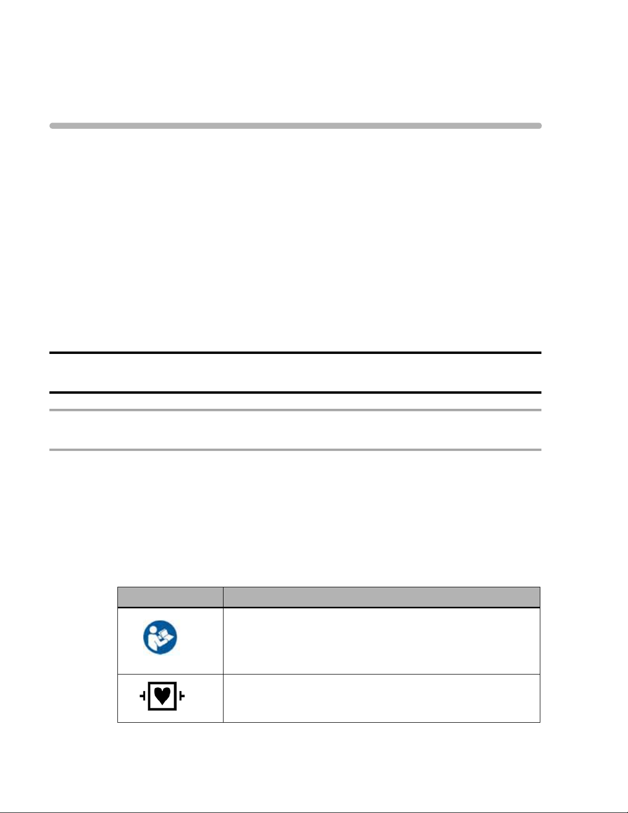
Symbols Marked on the ST80i System
Symbol Description
Attention. See the ST80i Instructions for Use and other product
documentation for information.
For information about the Advanced Interface Module, see
“Important Notes about the Advanced Interface Module” on page x.
ECG physio isolation is type CF, defibrillator proof. Suitable for all
patient applications including direct cardiac application. System is
in continuous operation.
i
Page 14
Safety Summary
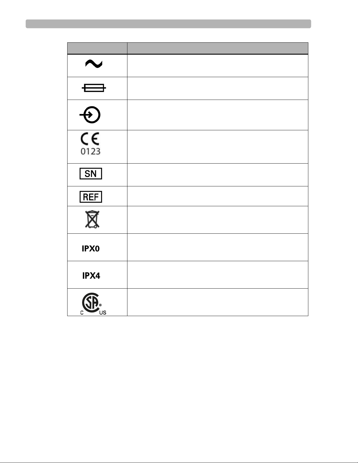
Symbol Description
Indicates that the system is receiving alternating currents.
Fuse
The connector near this symbol receives an incoming signal.
CE mark.
The number next to this symbol is the serial number of the system.
The number next to this symbol is the product model number of the
system.
Dispose of in accordance with the requirements of your country.
An International Protection Rating of “IPX0” indicates that the
equipment has no special protection against moisture ingress. The
ST80i System carries this rating.
An International Protection Rating of “IPX4” indicates that the
equipment is protected against slashing water from any angle. The
Wireless Patient Interface Module carries this rating.
Canadian Standards Association (CSA) Certification Mark.
Indicates that the product is certified for both the U.S. and Canadian
markets, to the applicable U.S. and Canadian standards.
ii ST80i Stress Test System Instructions for Use
Page 15

Symbols Marked on the ST80i System Packaging
Symbols Marked on the ST80i System Packaging
Symbol Description
Keep dry.
Keep out of direct sunlight.
Acceptable temperature range.
Move and store packaging this end up.
Fragile.
Recycle the packaging materials after use.
Manufacturer
Disposal Information
This product consists of devices that may contain mercury, which must be recy cled or
disposed of in accordance with local, state, or federal laws. (Within this system the backlight
lamps in the monitor display may contain mercury.)
Remove all batteries prior to disposing of any system components. Properly dispose of or
recycle depleted batteries according to local regulations. Then dispose of the device in
accordance with local, state, or federal regulations for equipment containing electronic parts.
ST80i Stress Test System Instructions for Use iii
Page 16

Safety Summary
Important Patient and Safety Information
Patient and safety information is divided into several sections:
ST80i Stress Test System (next section)
Medical isolation transformer (page ix)
Philips advanced interface module (AIM) (page x)
Philips wireless patient interface module (PIM) (page xi)
For information about electromagnetic compatibility (EMC) with surrounding devices, see
“Electromagnetic Compatibility (EMC) - To be finalized” on page E-7 of Appendix E,
“Specifications and Requirements”
Safety Information for the ST80i Stress Test System
The Philips ST80i Stress Test System, when operated with the ST80i AIM, AIM data cable,
ST80i PIM, and lead wires, shall meet all of the EMC requirements specified in the following
standards:
IEC 60601-1:1988 + A1:1991 + A2:1995 Medical Electrical Equip ment – Part 1 - General
requirements for basic safety and performance
AAMI EC11:8/2007 - Diagnostic Electrocardiographic Devices
IEC 60601-2-25:1993 + A1:1999 - Particular requirements for the safety of
electrocardiographs
AAMI EC53:12/2008 - ECG cables and leadwires
Warning Statements for the ST80i System
WARNING Failure to follow these warnings could affect both patient and operator safety.
Do not use the ST80i System in the presence of flammable vapors.
Do not use the ST80i System in the presence of explosive gases. AC power connection/
disconnection or electrostatic discharge (ESD) may result in spark occurring in an
environment where explosive gases are used.
Submersion and/or conditions that subject the ST80i System to liquid ingress create a
shock hazard.
When operating the ST80i System, ensure that the system and all other electrical
equipment connected to or near the patient are effectively grounded.
Do not touch accessible connector pins and the patient simultaneously.
The ST80i System has been safety tested with the recommended accessories, peripherals,
and leads, and no hazard was found when the system is operated with cardiac pacemakers
or other stimulators.
iv ST80i Stress Test System Instructions for Use
Page 17

Important Patient and Safety Information
To maintain designed operator and patient safety when assembling a medical electrical
system for use in the patient environment, the responsible organization shall ensure that
peripheral equipment and accessories used that can come in direct patient contact must
comply with the following standards:
– IEC 60601-1-1:2000 aka CAN/CSA-C22.2 No.60601-1-1:02
– EN 60601-1-2:2001 (all parts and particularly clause 19), titled, “Medical electrical
equipment - Part 1-1: General requirements for safety - Collateral Standard: Safety
requirements for medical electrical systems”
– EN 60601-1:2006 (clause 16 and particularly clause 16.6), titled, “Medical electrical
equipment - Part 1: General requirements for basic safety and essential performance”
Connecting multiple medical electrical instruments to the same patient may pose a safety
hazard due to the summation of leakage currents. Any combination of medical electrical
instruments should be evaluated by local safety personnel before being put into service.
For equipment not certified to medical electrical equipment standards that may be used
within the patient vicinity, an appropriately rated isolation transformer is required.
Do not connect to the system any items which are not specified as part of the system.
The PC, LCD, thermal printer, and desk light, purchased as part of a complete system
must be plugged into the medical-grade isolation transformer provided with ST80i.
Plug all accessories used with ST80i into the medical-grade isolation transformer
provided as part of the “software-only” solution.
Do not connect additional Multiple Portable Socket-Outlets (MPSOs) or extension cords
to the system.
The ST80i USB and RS-232 ports should be connected only to treadmills, ergometers, and
NIBP monitors that are certified to meet IEC 60601-1 and are listed as supported devices
in the Instructions for Use. See See “Supported Treadmills and Ergometers” on page 7. of
Appendix E, “Specifications and Requirements”.
The performance and safety of the ST80i System cannot be guaranteed if you use
non-compatible accessories.
Only computers, monitors, and printers approved by a National Certification Body (NCB)
or a Nationally Recognized Testing Laboratory (NRTL) to IEC 60950-1 shall be
connected to the ST80i system. All computer, monitor and printer outputs shall comply
with IEC 60950-1 limited power source requirements.
The use of ST80i with equipment (electrosurgical equipment and some respiration
transducers) that applies high frequency voltage to a patient is not supported and may
produce undesired outputs.
To prevent burns to the patient, remove all ECG electrodes and lead wires prior to the use
of high frequency surgical equipment (including electrosurgical equipment and some
respiration transducers).
Only install Philips software on the ST80i System. The installation or use of software,
security patches, or updates not approved by Philips is strictly prohibited and system
safety and performance are not guaranteed.
ST80i Stress Test System Instructions for Use v
Page 18

Safety Summary
Use only shielded LAN cable when connecting the cable to the ST80i LAN port.
Use Philips-approved lead wires with defibrillator protection resistors.
To avoid the possibility of serious injury or death during patient defibrillation, do not
come into contact with the wireless PIM or lead wires. Additionally, proper placement of
defibrillator paddles in relation to the electrodes is required to minimize harm to the
patient.
Do not contact floating electrodes during defibrillation, and avoid touching the lead wires
or conductive surfaces on the trolley during defibrillation.
Conductive parts of the patient lead wires, electrodes, and associated Type CF
connections, should not come into contact with other conductive parts, including earth
ground.
Electrodes of dissimilar metals should not be used.
Check lead wires, the cable between the PC and the treadmill, the cable between the PC
and the NIBP module, the AC adapter, and power cords daily for any worn or cracked
insulation to ensure that no inner conductive material is exposed. Discard worn
accessories and replace them only with Philips accessories.
The ST80i System should only use grounded power cords (three-wire power cords with
grounded plugs) and connect to grounded electrical outlets that are labeled as “Hospital
Only” or “Hospital Grade.” Never adapt a grounded plug to fit an ungrounded outlet by
removing the ground prong.
EMI generated by the ST80i System may cause nearby equipment to fail.
Short-range radio connections are subject to interruption due to interference from other
radio sources in the vicinity, including microwaves, bluetooth devices, and DECT phones.
Outside the frequency band and 5% above and below, i.e. the exclusion band according to
IEC 60601-1-2, the short-range radio connection is immune up to 3V/m in the frequency
range from 80 MHz to 2.5 GHz. Depending on the strength and duration of the
interference, the interruption may occur for an extended period. Any interruption of the
signal due to interference, moving out of range, or for other reasons is indicated via an RF
signal status indicator on both the PIM as well as on the main screen.
If your system includes the trolley, ensure that components are installed securely and that
no items are placed on the trolley that could cause the trolley to become unstable.
The maximum weight to be placed on the optional shelf for a laser printer is 45 pounds.
If your system includes the trolley, always lock the wheel brake when the trolley is not in
motion. Press down on the brake tab to set the brake and lift up on the tab to release the
brake.
Safe removal of the all-in-one display from the trolley requires two people.
Placing or spilling liquids on the trolley may cause electrical safety hazards and/or system
malfunction.
Allow the patient to move freely by:
vi ST80i Stress Test System Instructions for Use
Page 19

Important Patient and Safety Information
– taking care when dressing the ECG cables so as to minimize the potential tripping
hazard during the stress ECG study process
– securing the patient lead set, power cable, treadmill cable, echo cable, NIBP cable,
and SpO2 cable away from patient’s feet before beginning exercise stage
The ST80i captures and presents data reflecting a patient’s physiological condition that,
when reviewed by a trained physician or clinician, can be useful in determining a
diagnosis. However, the data should not be used as a sole means for determining a
patient’s diagnosis.
Both analog ECG output and TTL sync output are not in real time: there is a delay
between the patient’s physiological activity and the appearance of its representative signal
at the external port. This signal should not be used for analysis.
To get the most accurate interpretation during resting ECG, use traditional limb lead
placement.
For the user’s convenience only, rhythm change notifications are provided when specific
rhythm changes are detected; however, it is the responsibility of the trained healthcare
professional to determine the type of rhythm change and take appropriate action.
Additionally, the healthcare professional should not assume that all rhythm changes will
be detected, and they are responsible for taking action when rhythm changes are observed
on the displayed waveforms and the system fails to provide a notification. It is expected
that only properly trained healthcare professionals working directly under the supervision
of a qualified physician will be operating the ST80i System during testing.
ST80i cannot import ECGs from another vendor’s stress system.
“Simulated ECG” mode must be turned off when testing patients.
If the “Stop Treadmill” GUI button does not respond for any reason, immediately press the
red “Emergency” button on the treadmill handrail.
The interpretive algorithm has been validated only with “standard” lead placement.
If the patient data is found to be incorrect, you may edit the ECG file and can print a new
report.
Entering incorrect NIBP data can cause errors for NIBP-related parameters in reports.
Caution Statements for the ST80i System
CAUTION Caution statements describe conditions or actions that may result in damage to equipment or
software.
The Multiple Portable Socket-Outlet (MPSO) provided with the system shall only be used
for powering equipment which forms part of the system.
Do not pull or stretch patient lead wires as this could result in mechanical and/or electrical
failures. Store patient lead wires after forming them into a loose loop.
ST80i Stress Test System Instructions for Use vii
Page 20

Safety Summary
Do not attempt to clean the device or patient lead wires by submersion, autoclaving, or
steam cleaning.
Wipe the exterior surface of the device and patient lead wires with a compatible non-
alcohol sterilizing disinfectant, then dry with a clean cloth. See “Cleaning the ST80i
System” on page 5-2 in the “Maintaining the ST80i System” chapter for a list of approved
disenfectants.
Be careful not to damage the display when moving the trolley or when moving other
equipment near trolley.
To prevent possible damage to the device during transport and storage (while in original
packaging), the following environmental conditions must be adhered to:
Storage Temperature Range:
-20°C to 50°C (-4°F to 122°F)
Storage Humidity Range:
10% to 90% (non-condensing)
Storage Pressure (altitude):
Up to 4,572 m (15,000 ft.) altitude
Allow the device to stabilize within its intended operating environment for a minimum of
two hours prior to use. The allowable operating environment is as follows:
Operating Temperature Range:
10°C to 40°C (50°F to 104°F)
Operating Humidity Range:
10% to 90% (non-condensing)
Operating Pressure (altitude):
0 to 3,048 m (10,000 ft) altitude (697 mbar)
Important Notes about the ST80i System
ST80i may become inoperative when the front-end (PIM) signal acquisition is interrupted
due to low PIM battery power, loss of wireless communication between the PIM and the
receiver (AIM), and/or loss of USB communication between the AIM and the host PC.
ST80i displays a lead-off condition for all leads when signal acquisition is lost and
absence of signal strength bars when wireless communication is lost. These inoperative
conditions will be saved and indicated on printed reports.
Power off the system and remove the input AC power cord before installing, repairing, or
servicing any hardware.
Proper patient preparation is important for proper application of ECG electrodes and
operation of the device. Use medical tape to fix the lead wires to the chest in order to help
minimize the strain applied to the electrode connections, thus reducing noise and the
possibility of a leads-off condition.
ST80i automatically prevents connection to a LAN or WLAN while the system is
connected to a patient study.
As defined by IEC 60601-1 and IEC 60601-2-25, the device is classified as follows:
viii ST80i Stress Test System Instructions for Use
Page 21

Important Patient and Safety Information
– Class I equipment
– Type CF applied parts
– Ordinary equipment
– Not suitable for use in the presence of flammable anesthetics
– Continuous operation
Philips will make available on request circuit diagrams, component part lists, descriptions,
calibration instructions, or other information which will assist the user’s appropriately
qualified technical personnel to repair those parts of equipment which are designated by
the manufacturer as repairable.
Because of its sampling characteristics and the asynchronism between sample rate and
signal rate, ST80i may produce a noticeable modulating effect from one cycle to the next,
particularly in pediatric recordings.
ST80i can download ECGs via the TraceMasterVue server for review.
Safety Information for the Medical Isolation Transformer
Warning Statements about the Medical Isolation Transformer
WARNING Failure to follow these warnings could affect both patient and operator safety.
Use of this transformer with equipment other than originally supplied, or surpassing the
ratings, may cause damage, fire, or injury.
When using additional peripheral equipment powered from an electrical source other than
the isolation transformer, the combination is considered to be a medical system. It is the
responsibility of the operator to comply with IEC 60601-1-1 and test the medical system
according to the requirements. For additional information, contact Philips.
All components (whether supplied by Philips or purchased from another source) attached
to the ST80i PC, including the PC, printer, monitor, and optional blood pressure monitor,
must be plugged into a medical isolation transformer to ensure the system is properly
grounded. However, do not plug a laser printer into the isolation transformer provided
with ST80i. Power for the laser printer must be provided from another source that
complies with your facility’s safety requirements or IEC 60601-1.
Caution Statements about the Medical Isolation Transformer
CAUTION Caution statements describe conditions or actions that may result in damage to equipment or
software.
Before connecting your equipment to the isolation transformer, make sure the voltage
selector (located above the power cord) matches the line voltage.
ST80i Stress Test System Instructions for Use ix
Page 22

Safety Summary
Important Notes about the Medical Isolation Transformer
Do not connect the treadmill or the ergometer to the medical isolation transformer
supplied by Philips. It is important that the treadmill and ergometer has its own source of
unshared power to avoid an interruption to the power supply to the ST80i System. The
treadmill and ergometer should have its own circuit and fuse/breaker in a local power
distribution box.
Safety Information for the Advanced Interface Module
Warning Statements about the Advanced Interface Module
WARNING Failure to follow these warnings could affect both patient and operator safety.
FCC Warning: Changes or modifications not expressly approved by the party responsible
for compliance could void the user’s authority to operate the equipment.
Caution Statements for the Advanced Interface Module
CAUTION Failure to heed these caution statements may result in damage to equipment or software.
The advanced interface module complies with FCC radiation exposure limits set forth for
an uncontrolled environment.
Important Notes about the Advanced Interface Module
Use Conditions: This device complies with Part 15 of the FCC rules. Operation is subject
to the following two conditions:
– This device may not cause harmful interference
– This device must accept any interference received, including interference that may
cause undesired operation
The manufacturer is not responsible for any radio or TV interference caused by
unauthorized modifications to this equipment. Such modifications could void the user's
authority to operate the equipment.
FCC Note: This device has been tested and found to comply with the limits for a Class B
digital device pursuant to Part 15 of the FCC rules. These limits are designed to provide
reasonable protection against harmful interference in a residential installation. This device
generates, uses, and can radiate radio frequency energy and, if not installed and used in
accordance with the instructions, may cause harmful interference to radio
communications.
However, there is no guarantee that interference will not occur in a particular installation.
If this device does cause harmful interference to radio or television rece ption, which can
x ST80i Stress Test System Instructions for Use
Page 23

Important Patient and Safety Information
be determined by turning the device off and o n, the user is encouraged to try to correct the
interference by one or more of the following measures:
– Reorient or relocate the receiving antenna
– Increase the separation between the device and receiver
– Connect the device into an outlet on a circuit different from that to which the
receiver is connected
– Consult the dealer or an experienced radio/television technician for help
The radio device used in this product is in compliance with the essential requirements and
other relevant provisions of Directive 1999/5/EC (Radio Equipment and
Telecommunications Terminal Equipment Directive). Class 1 radio equipment. Member
states may apply restrictions on putting this device into service or placing it on the market.
Industry Canada Statement:
This device complies with RSS-210 of the Industry Canada rules. Operation is subject to
the following two conditions:
– This device may not cause harmful interference, and
– This device must accept any interference received, including interference that may
cause undesired operation.
Ce dispositif est conforme à la norme CNR-210 d'Industrie Canada applicable aux
appareils radio exempts de licence. Son fonctionnement est sujet aux deux conditions
suivantes:
– Le dispositif ne doit pas produire de brouillage préjudiciable, et
– Ce dispositif doit accepter tout brouillage reçu, y compris un brouillage susceptible de
provoquer un fonctionnement indésirable.
This Class B digital apparatus complies with Canadian ICES-003.
Cet appareil numérique de la classe B est conforme à la norme NMB-003 du Canada.
The AIM’s LED blinks every two seconds when the AIM is functioning properly. If the
AIM LED does not blink, the AIM is not functioning properly.
The 5-pin connector port on the back of the AIM is non-functional.
Do not connect TC series cardiograph patient interface modules to the 5-pin connector
port on the back of the AIM.
Safety Information for the Wireless Patient Interface Module
For information about electromagnetic compatibility (EMC) with surrounding devices, see
“Electromagnetic Compatibility (EMC) - To be finalized” on page E-7 of Appendix E,
“Specifications and Requirements”.
ST80i Stress Test System Instructions for Use xi
Page 24

Safety Summary
Warnings about the Wireless Patient Interface Module
WARNING Failure to follow these warnings could affect both patient and operator safety.
The wireless patient interface module transmits data reflecting a patient’s physiological
condition to a properly equipped system and when reviewed by a trained physician or
clinician can be useful in determining a diagnosis. However, the data should not be used as
a sole means for determining a patient’s diagnosis.
To maintain designed operator and patient safety when assembling a medical electrical
system for use in the patient environment, the responsible organization shall ensure that
peripheral equipment and accessories used that can come in direct patient contact must
comply with the following standards:
– IEC 60601-1-1:2000 aka CAN/CSA-C22.2 No.6 06 01-1 -1:0 2
– EN 60601-1-2:2001 (all parts and particularly clause 19), titled, “Medical electrical
equipment - Part 1-1: General requirements for safety - Collateral Standard: Safety
requirements for medical electrical systems”
– EN 60601-1:2006 (clause 16 and particularly clause 16.6), titled, “Medical electrical
equipment - Part 1: General requirements for basic safety and essential performance”
Any combination of medical electrical instruments should be evaluated by local safety
personnel before being put into service. For equipment not certified to medical electrical
equipment standards that may be used within the patient vicinity, an appropriately rated
isolation transformer is required.
FCC Warning: Changes or modifications not expressly approved by the party responsible
for compliance could void the user’s authority to operate the equipment.
To avoid the possibility of serious injury or death during patient defibrillation, do not
come into contact with device or lead sets. Additionally, proper placement of defibrillator
paddles in relation to the electrodes is required to minimize harm to the patient.
Defibrillation protection is guaranteed only if the original lead set is used.
Ensure that the electrodes or lead wires do not come in contact with any other conductive
materials (including earth-grounded materials), especially when connecting or
disconnecting electrodes to or from a patient.
If your facility is using more than one PIM, each one must be added to the ST80i
application under Settings (System Settings; I/O Devices). When you connect the patient
to one of the PIM devices, you also need to verify the address on the device with the
address that shows up on the Pre Exercise screen.
A possible explosion hazard exists. Do not use the device in the presence of flammable
anesthetics, or flammable mixtures with air, oxygen, or nitrous oxide.
Some stimulators may cause interference with the signal.
xii ST80i Stress Test System Instructions for Use
Page 25

Important Patient and Safety Information
Caution Statements for the Wireless Patient Interface Module
CAUTION Failure to heed these caution statements may result in damage to equipment or software.
The wireless patient interface module complies with FCC radiation exposure limits set
forth for an uncontrolled environment.
The wireless PIM supports 1.5V AA alkaline batteries only. Replace the battery if the
low-battery alert appears before the stress test starts.
The wireless PIM uses an off-the-shelf disposable AA alkaline battery for power. If you
use an off-the-shelf rechargeable AA battery, the remaining capacity indication may be
inaccurate.
Minimum operating time of the wireless PIM with new, fully charged batteries: 6 tests per
day, 30 minutes average per test, for 5 days. Performance may vary according to brand of
batteries used.
If you use off-the-shelf rechargeable batteries, then you must also provide a compatible
battery recharging unit independent of the ST80i System. To ensure safe use and adequate
maintenance of rechargeable batteries, follow the battery manufacturer’s instructions for
use.
Other than the replaceable battery, there are no user-serviceable parts inside. Any
modification of this device may alter defibrillator protection. Any modification to any part
of this device is to be performed by qualified service personnel only.
Follow the correct procedure to select the wireless PIM when multiple modules are
detected. See “Select the PIM” on page 3-13 of the “The Patient Session” chapter.
To prevent possible damage to the keypad, do not use sharp or hard objects to depress
keys; only use fingertips.
The wireless PIM and patient lead set should be cleaned between each use.
Do not attempt to clean the wireless PIM or patient lead set by submersion, autoclaving, or
steam cleaning. Wipe the exterior surface of the device and patient cables with a nonalcohol sterilizing disinfectant, then dry with a clean cloth. See “Cleaning the ST80i
System” on page 5-2 in the “Maintaining the ST80i System” chapter for a list of approved
disenfectants.
Conductive parts of the patient lead sets, electrodes, and associated Type CF connections,
including the neutral conductor of the patient cable and electrode, should not come into
contact with other conductive parts, including earth ground.
Do not pull or stretch patient lead sets as this could result in mechanical and/or electrical
failures. Store lead sets after forming them into a loose loop.
The following equipment may cause interference with the RF channel: microwave ovens,
diathermy units with LANs (spread spectrum), amateur radios, and government radar.
ST80i Stress Test System Instructions for Use xiii
Page 26

Safety Summary
Important Notes about the Wireless Patient Interface Module
Wireless patient interface module leakage currents are 100% safety tested in production.
Use Conditions: This device complies with Part 15 of the FCC rules. Operation is subject
to the following two conditions:
– This device may not cause harmful interference
– This device must accept any interference received, including interference that may
cause undesired operation
The manufacturer is not responsible for any radio or TV interference caused by
unauthorized modifications to this equipment. Such modifications could void the user's
authority to operate the equipment.
FCC Note: This device has been tested and found to comply with the limits for a Class B
digital device pursuant to Part 15 of the FCC rules. These limits are designed to provide
reasonable protection against harmful interference in a residential installation. This device
generates, uses, and can radiate radio frequency energy and, if not installed and used in
accordance with the instructions, may cause harmful interference to radio
communications.
However, there is no guarantee that interference will not occur in a particular installation.
If this device does cause harmful interference to radio or television rece ption, which can
be determined by turning the device off and on, the user is en couraged to try to correct the
interference by one or more of the following measures:
– Reorient or relocate the receiving antenna
– Increase the separation between the device and receiver
– Connect the device into an outlet on a circuit different from that to which the
receiver is connected
– Consult the dealer or an experienced radio/television technician for help
The radio device used in this product is in compliance with the essential requirements and
other relevant provisions of Directive 1999/5/EC (Radio Equipment and
Telecommunications Terminal Equipment Directive). Class 1 radio equipment. Member
states may apply restrictions on putting this device into service or placing it on the market.
Industry Canada Statement:
This device complies with RSS-210 of the Industry Canada rules. Operation is subject to
the following two conditions:
– This device may not cause harmful interference, and
– This device must accept any interference received, including interference that may
cause undesired operation.
Ce dispositif est conforme à la norme CNR-210 d'Industrie Canada applicable aux
appareils radio exempts de licence. Son fonctionnement est sujet aux deux conditions
suivantes:
– Le dispositif ne doit pas produire de brouillage préjudiciable, et
xiv ST80i Stress Test System Instructions for Use
Page 27

Important Patient and Safety Information
– Ce dispositif doit accepter tout brouillage reçu, y compris un brouillage susceptible de
provoquer un fonctionnement indésirable.
This ISM device complies with Canadian ICES-001.
Cet appareil ISM est conforme à la norme NMB-001 du Canada.
Proper patient preparation is important for proper application of ECG electrodes and
operation of the device.
Use wireless PIM belts and NIBP cuffs appropriate for the patient’s size.
Patient lead sets should be checked for cracks or breakage in its exterior properties prior to
use.
The wireless PIM includes LEDs that indicate battery power level, wireless signal quality ,
and lead contact status. When the wireless PIM is powered on, the battery power level
LED is lit. You can click the power button anytime to check the status of the battery,
wireless signal, or lead contacts.
As defined by IEC 60601-1 and IEC 60601-2-25, the device is classified as follows:
– Internally powered
– Type CF applied parts
– Ordinary equipment
– Not suitable for use in the presence of flammable anesthetics or flammable mixtures
of air, oxygen, or nitrous oxide
– Continuous operation
ST80i Stress Test System Instructions for Use xv
Page 28

Safety Summary
Security Recommendations
As more patient health information is collected, stored, and transmitted electronically, on a
global basis, the concern for patient privacy grows. We consider the security and
confidentiality of patient data to be of paramount importance. We adhere to the highest
professional standards focused on providing you with resources aimed at your regulatory
compliance needs and allowing you to fully manage the safety, effectiveness, and security
risks of medical devices, including your ST80i System.
Protecting Personal Information
It is essential that policies and procedures for the proper handling of personal or sensitive data,
consider the confidentiality, integrity, and the availability of these types of data. Each
organization using this product must provide the protective means necessary to safeguard
personal information consistent with each country law, code and regulation, and consistent
with the company policies for managing this information. While handling personal
information is outside the scope of this document; in g ene ral, each o rganizatio n is responsible
for identifying:
who has access to personal data and under what conditions an individual has authorization
to use that data
how the data is stored and the conditions by which it is stored
how the data is transmitted and the conditions under which that data is transmitted.
The US Department of Veterans Affairs has developed a widely used Medical Device
Isolation Architecture to minimize the risk of a security breach when medical devices are
connected to information networks. Such perimeter and network defenses are essential
elements in a comprehensive medical device security strategy.
Additional security and privacy information can be found on the Philips product security
website at: http://www.healthcare.philips.com/main/productsecurity/.
About HIPAA Rules
If applicable, your facility's security strategy should include the standards set forth in the
Health Insurance Portability and Accountability Act of 1996 (HIPAA), introduced by the
United States Department of Health and Human Services. You should consider both the
security and the privacy rules and the HITECH Act when designing policies and procedures.
For more information, please visit:http://www.hhs.gov/ocr/privacy/.
Security Controls and Safety Measures
The following controls and safety measures may further strengthen the security and
confidentiality of your patient records and system in general:
Install ST80i in a secure location and use a privacy filter on the ST80i System monitor that
shields the visibility of the screen contents from angled viewing.
In case of a power supply disruption, backup options shou ld be h andled by an app ropriate
power failover system.
xvi ST80i Stress Test System Instructions for Use
Page 29

Security Recommendations
Implement “best practices” Windows security measures to minimize unauthorized system
access. These measures include making passwords complex, regular changing of
passwords, short screen saver intervals, short auto logout intervals when the system is idle,
and training your users to lock the desktop when they leave the computer.
Install McAfee anti-virus software.
Apply Windows-recommended network security and user privilege policies to prevent:
– the installation of any software other than Philips-approved software intended for
installation on ST80i
– the transmission of viruses via removable storage devices (e.g., USB sticks)
Do not load or download to the computer any software, security patches, or updates not
authorized by Philips. Unathorized software may compromise the operation of the system
and is strictly prohibited.
Remember that the ST80i System contains confidential patient health information (PHI)
that should be safeguarded. Avoid copying pa tient health information to removable media.
If you do, maintain physical security of the media at all times. Deleting data from
rewritable/erasable media does not make the data inaccessible to a determined individual.
Dispose of removable media containing patient health information in accordance with
your institution’s policies.
Upon returning the equipment to Philips, eliminate all patient health information or other
confidential data, unless otherwise directed by Philips for problem investigation. Retain
only the information necessary for the investigation with full agreement from both parties.
Configure the system to not run executables (.exe files) automatically when connecting
external drives. See the ST80i Installation and Configuration Guide for more information.
Shut down remote desktop services as a best practice.
Rename the built-in Windows Administrator account.
Disable the Guest account. Every user should have his or her own identity.
Set up a BIOS password to prevent unauthorized access to the computer setting.
Although security safeguards to protect the system against the intrusion of malware
(viruses, trojans, worms, and so on) are recommended, a possibility remains that a system
can become infected. In all circumstances, the system safety mechanisms are designed to
remain intact, even when you might notice unfamiliar system behavior and performance.
If this happens repeatedly, such as after the system has been switched off and on again,
contact Philips customer support to have the system checked and, if needed, cleansed of
malware.
Malware prevention software should be configured to receive automatic updates. If the
virus scanning software has detected infection by malware, do not use automatic repair
utilities because the integrity of the repaired software cannot be guaranteed. Contact
Philips service to assess and repair the system. Additionally, please be sure to adhere to
local procedures regarding malware infection, which may include disconnecting from the
network until the situation is resolved.
ST80i Stress Test System Instructions for Use xvii
Page 30

Safety Summary
Perform regular backups of system data and store in a secure location. ST80i allows you to
back up the stored ECG report and the configuration setting. Users with adminstrator
accounts can backup and restore ECG reports from the “Archive” screen; administrators
can also backup the configuration setting on the “Settings” screen.
The exported configuration setting can be imported on the “Settings” screen to restore the
ST80i software.
User must maintain physical security of the media that stores the backup files at all times.
You risk losing ePHI if you transfer it to unsupported and/or obsolete backup media
(e.g., floppy disks).
Limit W eb browsing to the downloading of Philips-authorized security patches or updates.
Web as browsing dramatically increases the chance of the system being infected by
malicious software.
ST80i is not generally used in situations where emergency access is required. If this is
important to your organization, it is recommended that you establish administrative
procedures to permit emergency access to the device when normal logon and
authentication credentials are not available.
Visit the Philips security website at http://www.healthcare.philips.com/main/
productsecurity/ for the latest security updates from Philips.
xviii ST80i Stress Test System Instructions for Use
Page 31

The Philips ST80i Stress Test System
Intended Use
The Philips ST80i Stress Test System is a PC-based diagnostic tool intended to acquire,
process, and store ECG data of patients undergoing stress exercise testing. The software
records ECG, heart rate, and ST data, creates summary tables, trends, and produces a final
report regarding a variety of cardiac data indices. The cardiac data provided by the Stress
system is intended to be reviewed, confirmed, and used for diagnostic purposes by trained
medical personnel to assist in the diagnosis of CAD and the patient's physiological condition
during stress exercise testing. The arrhythmia detection portion of the ST80i Stress Test
System is provided to the user for the convenience of automatic detection of arrhythmias but
does not provide alarms.
Indications for Use
The Philips ST80i Stress Test System is indicated for use in exercise ECG testing where the
clinician decides to evaluate the electrocardiogram of patients at 10 years or older, as part of
decisions regarding possible diagnosis, potential treatment, effectiveness of treatment, or to
rule out causes for symptoms of CAD. The Philips ST80i Stress Test System is not intended to
be used as a physiological monitor.
The Philips ST80i Stress Test System
The CAlg-STR Exercise ECG Analysis Algorithm
Intended Use
The intended use of the CAlg-STR Exercise ECG analysis algorithm is to analyze multichannel ECG waveforms acquired from a patient and produce measurements such as heart
rate, detect ventricular arrhythmias, form representative beats, and calculate ST segment
deviation (elevation or depression) and ST slope for review by a trained physician or clinician
in determining a diagnosis. The measurements should not be used as a sole means for
determining a patient’s diagnosis.
Indications for Use
The analysis algorithm is indicated for use in those situations where the clinician decides to
evaluate the electrocardiogram of patients at 10 years old and old er, as part of decisions
regarding possible diagnosis, potential treatment, effectiveness of treatment or to rule out
causes for symptoms. The analysis algorithm is not intended to be used as a physiological
monitor.
ST80i Stress Test System Instructions for Use xix
Page 32

Safety Summary
xx ST80i Stress Test System Instructions for Use
Page 33

1
1About the Philips ST80i Stress Test
System
The Philips ST80i Stress Test System is a PC-based diagnostic tool for use in the exercise
stress testing laboratory. Electrocardiographic data obtained during stress testing is acquired,
processed, recorded, analyzed, archived, and exported. The ST80i software creates summary
tables, identifies trends, and generates a final statistical report, which trained clinicians review
to assist in the diagnosis of the patient’s condition.
The ST80i System interfaces to, and controls, a compatible treadmill or ergometer and noninvasive blood pressure monitor. It can also be used with the pharmacological form of testing.
The TTL and analog output options allow a selectable ECG signal to be sent to an Echo
system for further tests.
This chapter provides the following information:
Overview . . . . . . . . . . . . . . . . . . . . . . . . . . . . . . . . . . . . . . . . . . . . . . . . . . . . . .1-2
About the Testing Process Using ST80i. . . . . . . . . . . . . . . . . . . . . . . . . . .1-3
About ST80i Documentation. . . . . . . . . . . . . . . . . . . . . . . . . . . . . . . . . . . . . . .1-4
Available Documentation . . . . . . . . . . . . . . . . . . . . . . . . . . . . . . . . . . . . . .1-4
Conventions Used in this Guide. . . . . . . . . . . . . . . . . . . . . . . . . . . . . . . . .1-5
How to Use this Guide . . . . . . . . . . . . . . . . . . . . . . . . . . . . . . . . . . . . . . . .1-5
Getting Help Using ST80i . . . . . . . . . . . . . . . . . . . . . . . . . . . . . . . . . . . . .1-7
1-1
Page 34

About the Philips ST80i Stress Test System
Overview
The ST80i System is a PC-based diagnostic tool intended to acquire, process, and store ECG
data of patients undergoing stress exercise testing. The software records ECG, heart rate, and
ST data, creates summary tables, trends, and produces a final report regarding a variety of
cardiac data indices. The cardiac data provided by the stress system is intended to be reviewed,
confirmed and used for diagnostic purposes by trained medical personnel to assist in the
diagnosis of coronary artery disease (CAD) and the patient’s physiological condition during
stress exercise testing
NOTE The arrhythmia detection portion of ST80i is provided for the convenience of automatic
documentation. ST80i does not offer a diagnostic opinion; rather, it provides a high-fidelity instrument
recording ECG waveforms during exercise, for the purpose of providing a tool to expedite the
documentation of a test for which a clinician renders his/her own medical opinion.
ST80i provides the standard 12-lead ECG by the use of the 10-lead electrode wireless patient
interface module (PIM).
Key features provided by ST80i include the following:
Continuous ECG acquisition and analysis (ST level, risk scoring & alerts)
.
Heart rate, blood pressure & SpO
Intuitive user interface – no user training required
Comprehensive test protocol support
Comprehensive and customizable reports
Comprehensive connectivity (EMR/HIS, TMVue)
Customizable display layout
Wireless patient connection
Support for exercise, pharmacological, and nuclear stress testing
Interface to ADT For patient registration
Remote access to reports
monitoring, display and trending
2
ST80i is also programmable, allowing you to customize the operational conditions to suit your
needs. You can customize:
Up to 100 different user profiles to meet the needs of individual physicians
Up to 100 different exercise protocols
Automatic 12-lead ECGs
Multiple final report formats
ST80i runs on a PC with the Windows 7 operating system. You control its functions using the
keyboard and mouse or touch screen.
1-2 ST80i Stress Test System Instructions for Use
Page 35

ST80i interfaces with a treadmill, ergometer, or as part of a pharmacological study, and
captures four phases of a patient exercise test:
Pre-exercise
Exercise
Recovery (and Post-Recovery)
Report
About ST80i Documentation
Philips provides detailed instructional and reference materials to help you get the most out of
your ST80i System.
Available Documentation
About ST80i Documentation
The following documentation is available with the ST80i system:
Getting Started Sheet Introduces the product, lists the contents, and directs the user to the
installation materials and documentation.
ST80i Installation and
Configuration Guide
Describes how to set up the ST80i System, including hardware and
software. Also describes how to set up the trolley and how to
perform initial configuration of the software.
ST80i Instructions for
Use (IFU)
Provides detailed information about ST80i functionality. It
describes the operation of the product and includes all regulatoryrequired labeling. This guide also includes troubleshooting and
maintenance information. The IFU is written for clinical
professionals. They are expected to have a working knowledge of
medical procedures and medical terminology as required for
monitoring potential cardiac patients.
Wireless Patient
Interface Module
Instructions for Use
Provides information about how to set up the Philips wireless
patient module and also includes all regulatory-required labeling.
Includes a troubleshootingchapter and a service/maintenance
chapter.
C-Alg STR
Physician’s Guide
Describes the ECG analysis program available on the ST80i
System, and the available report formats. Includes a high-level
description of the criteria logic.
ST80i Service Manual Provides guidelines for repair on specific parts as well as
information for how to order replacement parts.
ST80i Stress Test System Instructions for Use 1-3
Page 36

About the Philips ST80i Stress Test System
Conventions Used in this Guide
The documentation and training materials for ST80i use the following typographic
conventions.
Item How Displayed
Menu item
Button name
Field names and list
items
Menu items and button names appear in a bold no-serif font.
Example: Click
Settings.
Field names and list items appear in a no-serif font.
Example: Select the appropriate format from the
Format dropdown
list.
WARNING Warning statements describe conditions or actions that may result in injury to the
patient.
CAUTION Caution statements describe conditions or actions that may result in damage to equipment or
software.
NOTE Notes provide additional important information about a topic.
How to Use this Guide
This guide is intended to help you use ST80i. It also provides maintenance and
troubleshooting information, as well as product specifications.
This guide is organized as follows:
Safety Summary. Lists the warnings, caution statements, and important notes
that apply to using the ST80i system, the patient modules, and the isolation
transformer. Read this chapter before operating any of the equipment.
1
About the Philips ST80i Stress Test System. Provides a high-level
overview of the ST80i System.
2
Philips ST80i Stress Test System Overview. Provides a general overview of
the ST80i graphical user interface, features, and functionality. It also provides
basic information about changing specific default settings during a Patient
Session.
3
The Patient Session. Describes all aspects of the patient session, from getting
started through the four phases of the test.
4
Working with Reports. Describes how to configure, view, edit, save, and print
the final stress test report.
1-4 ST80i Stress Test System Instructions for Use
Page 37

About ST80i Documentation
5
A
B
D
E
Maintaining the Philips ST80i Stress Test System. Describes how to clean
and maintain the system.
Troubleshooting and Contacting the Response Center. Describes some
issues you might encounter and what to do about them. Also describes how to
contact the Philips Response Center.
Protocol Reference. Provides an example of the settings for each of the
protocols provided with ST80i.
Ordering Options and Parts. Provides a list of parts (including support parts)
) and options you can order.
Specifications and Requirements. Lists the product specifications.
Glossary. Defines common terms used with the ST80i System.
Getting Help Using ST80i
For detailed troubleshooting information, as well as details about contacting the Philips
Response Center, see Appendix A, “Troubleshooting and Contacting the Response Center.”
ST80i Stress Test System Instructions for Use 1-5
Page 38

About the Philips ST80i Stress Test System
1-6 ST80i Stress Test System Instructions for Use
Page 39

2
1An Overview of the ST80i Stress Test
System
The ST80i Stress Test System is used for the acquisition, analysis, and presentation of stress
test data during the patient session. The application also controls the peripheral devices such
as the treadmill, ergometer, and blood pressure equipment.
A patient session is the period of time when the exercise stress test is performed and
waveforms are acquired and processed for a single patient. Patient information is linked with
all waveform data acquired during the patient session. The session starts when you begin to
gather exercise data for a new exam and lasts through the generation and review of the final
report.
During the patient session, you can change certain default settings as you proceed through
each phase using the Toolbar icons - so that you can view or gather more specific ECG data.
Other changes can be made directly o n the screen as yo u proceed through the various stages of
the exam. This may involve changing the default protocol, manually inserting a blood pressure
measurement, or manually taking control of the exercise device. In addition, you can select
from various print options during the patient session.
This chapter provides the following information:
User Accounts . . . . . . . . . . . . . . . . . . . . . . . . . . . . . . . . . . . . . . . . . . . . . . . . . .2-3
Starting the Application . . . . . . . . . . . . . . . . . . . . . . . . . . . . . . . . . . . . . . .2-3
User Profile. . . . . . . . . . . . . . . . . . . . . . . . . . . . . . . . . . . . . . . . . . . . . . . . .2-4
ST80i Test Screen . . . . . . . . . . . . . . . . . . . . . . . . . . . . . . . . . . . . . . . . . . . . . . .2-5
Title Bar . . . . . . . . . . . . . . . . . . . . . . . . . . . . . . . . . . . . . . . . . . . . . . . . . . .2-6
Procedure Bar . . . . . . . . . . . . . . . . . . . . . . . . . . . . . . . . . . . . . . . . . . . . . . .2-7
Toolbar . . . . . . . . . . . . . . . . . . . . . . . . . . . . . . . . . . . . . . . . . . . . . . . . . . . .2-8
Waveform Screen . . . . . . . . . . . . . . . . . . . . . . . . . . . . . . . . . . . . . . . . . . . .2-9
Side Panel . . . . . . . . . . . . . . . . . . . . . . . . . . . . . . . . . . . . . . . . . . . . . . . . . . . .2-10
Heart Rate bpm. . . . . . . . . . . . . . . . . . . . . . . . . . . . . . . . . . . . . . . . . . . . .2-11
Target Heart Rate (130) . . . . . . . . . . . . . . . . . . . . . . . . . . . . . . . . . . . . . .2-11
Max (220) . . . . . . . . . . . . . . . . . . . . . . . . . . . . . . . . . . . . . . . . . . . . . . . . .2-12
BP mmhg . . . . . . . . . . . . . . . . . . . . . . . . . . . . . . . . . . . . . . . . . . . . . . . . .2-12
Previous BP mmhg . . . . . . . . . . . . . . . . . . . . . . . . . . . . . . . . . . . . . . . . . .2-12
SpO2 . . . . . . . . . . . . . . . . . . . . . . . . . . . . . . . . . . . . . . . . . . . . . . . . . . . . .2-12
Double Product (HR*BP). . . . . . . . . . . . . . . . . . . . . . . . . . . . . . . . . . . . .2-13
About METS . . . . . . . . . . . . . . . . . . . . . . . . . . . . . . . . . . . . . . . . . . .2-13
About ST X mm – by Zoom Lead . . . . . . . . . . . . . . . . . . . . . . . . . .2-13
Treadmill Speed, Grade % . . . . . . . . . . . . . . . . . . . . . . . . . . . . . . . . . . . .2-13
2-1
Page 40

An Overview of the ST80i Stress Test System
Treadmill Button . . . . . . . . . . . . . . . . . . . . . . . . . . . . . . . . . . . . . . . .2-14
Ergometer Button. . . . . . . . . . . . . . . . . . . . . . . . . . . . . . . . . . . . . . . .2-14
Using the Toolbar Icons . . . . . . . . . . . . . . . . . . . . . . . . . . . . . . . . . . . . . . . . .2-14
Waveform . . . . . . . . . . . . . . . . . . . . . . . . . . . . . . . . . . . . . . . . . . . . . . . . .2-17
Hide/Show View. . . . . . . . . . . . . . . . . . . . . . . . . . . . . . . . . . . . . . . . . . . .2-17
About the Lead Map. . . . . . . . . . . . . . . . . . . . . . . . . . . . . . . . . . . . . .2-18
About the Zoom ST . . . . . . . . . . . . . . . . . . . . . . . . . . . . . . . . . . . . . .2-19
About the ST Map . . . . . . . . . . . . . . . . . . . . . . . . . . . . . . . . . . . . . . .2-20
About Trend View . . . . . . . . . . . . . . . . . . . . . . . . . . . . . . . . . . . . . . .2-21
About HR/METS . . . . . . . . . . . . . . . . . . . . . . . . . . . . . . . . . . . . . . . .2-22
About ST J+ mV . . . . . . . . . . . . . . . . . . . . . . . . . . . . . . . . . . . . . . . .2-22
About BP . . . . . . . . . . . . . . . . . . . . . . . . . . . . . . . . . . . . . . . . . . . . . .2-23
About the Average Complex Dis play . . . . . . . . . . . . . . . . . . . . . . . .2-23
Freeze . . . . . . . . . . . . . . . . . . . . . . . . . . . . . . . . . . . . . . . . . . . . . . . . . . . .2-24
Recording an Event. . . . . . . . . . . . . . . . . . . . . . . . . . . . . . . . . . . . . . . . . .2-24
Recording RPE . . . . . . . . . . . . . . . . . . . . . . . . . . . . . . . . . . . . . . . . . . . . .2-26
Note. . . . . . . . . . . . . . . . . . . . . . . . . . . . . . . . . . . . . . . . . . . . . . . . . . . . . .2-27
Compare . . . . . . . . . . . . . . . . . . . . . . . . . . . . . . . . . . . . . . . . . . . . . . . . . .2-27
Page. . . . . . . . . . . . . . . . . . . . . . . . . . . . . . . . . . . . . . . . . . . . . . . . . . . . . .2-28
Gear (Quick Settings) . . . . . . . . . . . . . . . . . . . . . . . . . . . . . . . . . . . . . . . .2-29
Filter. . . . . . . . . . . . . . . . . . . . . . . . . . . . . . . . . . . . . . . . . . . . . . . . . .2-29
Display . . . . . . . . . . . . . . . . . . . . . . . . . . . . . . . . . . . . . . . . . . . . . . . .2-30
Rhythm Print . . . . . . . . . . . . . . . . . . . . . . . . . . . . . . . . . . . . . . . . . . .2-31
Sync Out. . . . . . . . . . . . . . . . . . . . . . . . . . . . . . . . . . . . . . . . . . . . . . .2-31
2-2 ST80i Stress Test System Instructions for Use
Page 41

User Accounts
User accounts are created with specific access privileges based on function. ST80i user
accounts are categorized as follows:
Administrators – these users are allowed to perform all operations on the system.
Clinicians – these users are allowed to perform all operations on the system except most
configuration operations. The only configuration that the Clinician would be able to
perform is report configuration for fine tuning on final reporting (“Finalizing”).
Technicians – these users are allowed to perform all operations on the system except
configuration and “Finalizing.”
Only clinicians and administrators would be able to electronically sign the report.
ST80i supports at least 100 user accounts.
Starting the Application
User Accounts
Your user account is used to access the application. When you log into ST80i, you are logging
into your preconfigured user profile.
To log in
1
Double-click the ST80i icon on your desktop. The ST80i window opens.
2 Type your User Name and Password.
3 Click OK.
The Main screen opens.
Figure 2-1 Main screen
ST80i Stress Test System Instructions for Use 2-3
Page 42

An Overview of the ST80i Stress Test System
The Main screen is where you perform all tasks for the application.
To conduct a stress test, click Patient.
To enter the stress system database to review and retrieve archived reports, click Report.
In this area, you can also replay, delete, or export a selected exercise stress test.
To review, update, or test software and firmware configurations, click Service.
To hear an audio explanation of the exercise stress test, click Explain Test.
NOTE ST80i ships with a default audio file that explains the exercise stress test; however, you may record
your own audio file and configure ST80i to play this file when the user clicks the Explain Test button.
For more information, see the ST80i Installation and Configuration Guide.
To preconfigure or change system settings, user profiles, exercise protocols and user
accounts, click
Settings.
2-4 ST80i Stress Test System Instructions for Use
Page 43

User Accounts
User Profile
The system ships with a default user profile that cannot be deleted. The user profile contains
preconfigured settings that are used to determine how the test will run and how the test results
will be displayed, printed, saved, and exported. Some settings are fixed and cannot be
changed; some settings represent a default view, which can be changed during the exercise
stress test.
The preconfigured parameters of the user profile include:
Exercise protocol and equipment
Lead formats
Display settings
Report settings
Freeze display
Filter settings
Algorithm settings
Notifications
Audio prompts
See “Using the Toolbar Icons” on page 2-15 for an explanation of the settings that can be
changed during the patient session. See also “Side Panel” on page 2-11 for an explanation of
the display features that are continuously updated during the patient session. On this panel you
can manually override blood pressure and SpO
, as well as equipment settings that are
2
preconfigured as part of the user profile and/or protocol.
Refer to the ST80i Installation and Configuration Guide for an explanation of how user
profiles are pre-configured.
Before beginning with the exercise stress test, it's important to understand the key features of
the ST80i user interface along with the Toolbar icons, since you will be using them during the
patient session.
ST80i Stress Test System Instructions for Use 2-5
Page 44

An Overview of the ST80i Stress Test System
A
B
C
D
E
ST80i Test Screen
The ST80i Test screen (user interface) provides:
All key procedural information including the protocol being used
Pop-ups, drill-down menus, and notes pages that can be viewed then hidden so that the
leads can be viewed in their entirety
Time of Day for correct time stamp on the start-up screen for every stress test
Real-time ECG as well as NIBP and SpO
, Trends, and other numeric displays that
2
include ST values, ST slope, Double Product, and ST/HR index
On the Test screen, you have command of several functions during a patient session. You can
adjust the speed and elevation of a treadmill and insert manual blood pressure data. You can
also abort the exam at any point without losing any patient data. However, note that the
exercise data will be lost.
Figure 2-2 ST80i Test screen
Table 2-1 ST80i Test Screen Features
Feature Description
A
Title Bar - displays patient name date of birth and ID, along with current date
and time; during the patient session, you can click the patient name in the Pre
Exercise phase or Report phase to update patient information; also where the
PIM battery status and RF transmitter LED indicators appear.
2-6 ST80i Stress Test System Instructions for Use
Page 45

Feature Description
AB C DEF
ST80i Test Screen
B
C
Procedure Bar - used to control the exercise stress test process; shows exercise
stage; selected patient interface device; protocol;
Print
buttons; and stage time
BP, ECG Print and Rhythm
Toolbar - displays the Toolbar icons that provide quick access to frequently
used commands throughout the exercise stress test
D
Waveform Screen - provides real-time ECG waveforms during the exercise
stress test
E
Side Panel - provides real-time updates during the stress test as well as target
heart rate, NIBP and SpO
, and exercise equipment data (speed, grade, stop &
2
start)
Title Bar
At any time during the Pre Exercise or Report phases of the patient session, you can use the
title bar to manually input and edit patient information with data that will be centrally stored in
the stress database. The Title Bar includes the features shown and described below.
Figure 2-3 TitleBar
Table 2-2 Title Bar Features
Feature Description
A
Navigation Keys [Main Test] - Click Main to leave exercise test and return to
Main screen
B
C
D
E
F
Patient Name - Click the patient name to update patient information and add
notes on the
Patient Information tab of the Patient Demographics screen
Patient's Date of Birth
Patient ID
LED indicators for the RF Transmitter and PIM battery status
Current Date and Time
ST80i Stress Test System Instructions for Use 2-7
Page 46

An Overview of the ST80i Stress Test System
To add or update patient information
1
Click on the Patient Name in the title bar.
The system displays the Patient Demographics window.
Figure 2-4 Patient Demographics window
Enter new information for the patient or update the fields as needed during the stress test.
2
3 Click OK when finished to save the data.
If you manually update patient information, including Notes and Symptoms during the test or
on the Report screen, this information is not updated in the Patient profile in Worklist.
2-8 ST80i Stress Test System Instructions for Use
Page 47

ST80i Test Screen
ABCDEF
G
H
I
Procedure Bar
By default, the Procedure Bar is at the top of the screen. You can change the location of the
Procedure Bar to the bottom of the screen. See the ST80i Installation and Configuration Guide
to change the default setting [Settings User Profile Display].
Figure 2-5 Procedure Bar
Table 2-3 Procedure Bar Features
Feature Description
A
B
C
D
E
F
G
H
I
Current exercise phase (Pre Exercise, Exercise, Recovery, Report)
PIM device (only in the Pre Exercise stage)
Protocol (Protocol drop-down list)
button - used to manually command the optional automatic blood pressure
BP
(NIBP) device to take an unscheduled blood pressure measurement
Print ECG
Rhythm print
Advance
button
button
(to the next stage) or Stop buttons
Exercise stage and time
Phase buttons (Pre Exercise, Exercise, Recovery, Report) - next phase is
illuminated in green
ST80i Stress Test System Instructions for Use 2-9
Page 48

An Overview of the ST80i Stress Test System
Toolbar
The Toolbar contains the Toolbar icons that are used during the patient session. The icons
provide quick access to frequently used commands.
During the patient session, the waveform screen is displayed. You can use the Toolbar icons
during the patient session to view or hide specific exercise stress test data - which appear as an
overlay on the waveform screen.
Some of the icons allow you to change specific default settings as you proceed through each
phase of the patient session, while others give you a magnified view of various data in relation
to the ECG.
When you mouse over each icon, a Tool Tip is displayed.
See “Using the Toolbar Icons” on page 2-15 for a complete description of the icons and their
functionality.
The default setting for the Toolbar is at the top of the screen. You can change the location of
the Toolbar to the bottom of the screen. See the ST80i Installation and Configuration Guide to
change the default setting [Settings User Profile Display].
Waveform Screen
Real-time ECG waveforms appear on the Waveform screen. The default setting is 12-Lead.
With the customizable options of ST80i, you can use the Toolbar icons do the following:
Change the default lead you want to view (12, 6x2, 6, 3)
Display the magnified beat
Display and/or print the average complexes
Show or remove magnified beat, trends, anatomical representations and average
complexes from the ECG print strip
On the bottom of the screen, the current settings appear for the following:
Limb Lead amplitude
Chest Lead amplitude
Speed of trace display
Filter – low and high pass
Figure 2-6 Limb Lead, Chest Lead, Speed, and Filter Settings
When you change these default settings using the Toolbar icons, they appear in this location.
2-10 ST80i Stress Test System Instructions for Use
Page 49

Side Panel
A
B
C
D
E
F
G
H
I
The Side Panel shows a continuous display of all relevant physiological parameters as well as
visual indicators for current heart rate and a dynamic change in heart rate. From the Side
Panel, you can override NIBP and SpO
speed and duration during a patient session or stop the treadmill altogether.
The Side Panel provides the following:
Figure 2-7 Side Panel
Side Panel
values. In addition, you can change the treadmill
2
ST80i Stress Test System Instructions for Use 2-11
Page 50

An Overview of the ST80i Stress Test System
Table 2-4 Side Panel Features
Feature Description
A
B
C
D
E
F
G
Heart rate beats per minute
Target heart rate – visual and audible indicators when target heart rage is
achieved
Maximum heart rate
BP mmhg – current blood pressure; used also to manually insert current BP
measurement
Previous BP mmhg – when BP is taken as pre-configured by stage, previous
BP is shown; previous BP is also shown when you manually insert current BP
measurement
SpO2 numeric data with appropriate stage; you can manually insert SpO2 data
DP hr*bp (Double-Product – default); drop-down includes:
METS – establishes metabolic equivalent [Algorithm calculation of HR,
speed of Treadmill, etc.]
ST mm – ST Index
H
I
Treadmill speed (mph), grade %, or ergometer watts
Treadmill or Ergometer button (S tart/S t op). The button displays “Unavailable”
when the treadmill or ergometer is unavailable.
Heart Rate bpm
This field shows the current heart rate of the patient.
Target Heart Rate (130)
There are visual and audible indicators when the target heart rate is achieved.
This field shows the % of Target Heart Rate achieved.
Target Heart Rate is X% of maximum heart rate – as established in User Profile
Target Heart Rate % is pre-set (typically 85%)
See the information regarding Target Heart Rate in the ST80i Installation and Configuration
Guide.
2-12 ST80i Stress Test System Instructions for Use
Page 51

Side Panel
Max (220)
Shows the maximum heart rate for patient, male or female.
BP mmhg
When the patient's NIBP is collected during the exercise stress test based on the defined
interval in the Exercise Protocol (Off, Begin, End, Every), the BP mmgh field displays the
measurement. If you click the
measurement also displays in this field.
With this interface, there are visual and audio prompts (if enabled) for NIBP acquisition.
To enable audio alerts, see the ST80i Installation and Configuration Guide.
This field is also used to manually enter a blood pressure measurement, if an NIBP monitor is
not being used.
To override NIBP or manually insert the blood pressure measurement
BP button during the patient session, the current blood pressure
NOTE Once the NIBP or BP is manually overwritten, ST80i no longer updates the real-time value from the
NIBP monitor.
1
Click the dashed lines or current BP value in the BP mmhg field.
2 Type in the blood pressure measurement.
3 Click OK.
Previous BP mmhg
When the blood pressure monitor records the current blood pressure measurement, the
Previous BP mmgh field displays the previous measurement. It will also display the previous
blood pressure measurement when you click the
If you are using a blood pressure cuff, when you manually enter the blood pressure
measurement, this field records the previous blood pressure measurement.
SpO
2
The patient’s SpO2 is collected in real time through a sensor. During the stress test, SpO2 is
measured automatically and is continuously displayed on the screen. With this interface, there
are also visual and audio prompts (if enabled) for SpO
BP button on the Procedure bar.
acquisition.
2
To enable audio alerts, see the ST80i Installation and Configuration Guide.
You can override the NIBP and SpO
need to manually enter the SpO
values. Depending on the NIBP monitor used, you may
2
data.
2
ST80i Stress Test System Instructions for Use 2-13
Page 52

An Overview of the ST80i Stress Test System
To override or manually enter the Sp0
1 Click the dashed lines or value.
2 Type in the latest SpO
3 Click OK.
2
2
Double Product (HR*BP)
Double Product is the current heart rate times the current blood pressure measurement.
Use the drop-down arrow to change from Double Product display to the following:
About METS
About ST X mm (or mV) – X is the selected Zoom Lead
About METS
The METS calculation establishes a metabolic equivalent based on the Algorithm calculation
of HR, speed of treadmill, etc.
About ST X mm – by Zoom Lead
You have the option to change the lead in view using the drop-down menu to view the ST
Index (ST level).
To change the lead in view
1
Click the Hide/Show View icon.
2 Select Show Zoom ST.
3 Click the Lead drop-down arrow in the Zoom ST lead display.
4 Select the lead to view.
Treadmill Speed, Grade %
These two fields capture the treadmill speed and elevation by stage.
You can also use these fields to manually change the treadmill speed and elevation. To do
this, see “Controlling the Treadmill or Ergometer” on page 3-35.
During the entire stress test, the host-side application validates the response between the
treadmill (or ergometer) and the PC to ensure that the communication is successful.
2-14 ST80i Stress Test System Instructions for Use
Page 53

Using the Toolbar Icons
Treadmill Button
The Treadmill button is used to stop and start the treadmill during a patient session.
WARNING The ST80i USB and RS-232 ports should be connected only to treadmills, ergometers, and NIBP
monitors that are certified to meet IEC 60601-1 and are listed as supported devices in the Instructions
for Use. See “Supported Treadmills and Ergometers” on page E-7 of Appendix E, “Specifications and
Requirements”.
CAUTION If the “Stop Treadmill” GUI button does not respond for any reason, immediately press the red
“Emergency” button on the treadmill handrail.
Ergometer Button
The Ergometer button is used to stop and start the ergometer during a patient session.
Using the Toolbar Icons
Generally, you will not change the settings associated with a selected profile and protocol
during an exercise stress test. However, there may be instances when you wish to change
specific display settings. You can change display settings by using the Toolbar icons.
Figure 2-8 Toolbar Icons
When you mouse over each icon, a Tool Tip is displayed.
Using the
Select what leads to view in real time
Change the default setting of the waveforms on the waveform screen
Display a zoomed view of an average complex to either a specified lead or for the lead that
Freeze the ECG or enable a filter to reduce noise
Use the lead map diagram to check the lead wire contact with a predefined, color-coded
Toolbar icons, you can do the following:
shows the most significant change in ST level
indicator to show which lead is off
ST80i Stress Test System Instructions for Use 2-15
Page 54

An Overview of the ST80i Stress Test System
Compare the current averages with reference ECG (resting, supine, hyperventilation
averages) and worst case for all 12 leads. ST80i is able to select a new ECG complex or
10s strip as the new reference. This can be done on the screen and is available at any point
during the test.
Hide or show the magnified beat, trends, anatomical representations (ST Map) and
average complexes that appear over the real-time waveform display
View a two-dimensional, color-coded anatomical representation of ischemic area/
segments (ST Map); 2D real-time updates anatomical representation (ST Map) every 10
seconds
Create events during the test with associated notes
View trend graphs for Heart Rate, METS, BP, SpO
View magnified ST and morphological changes (including ST morphology changes, T
, and ST values at any time
2
wave morphology changes, QRS morphology changes) in the various leads.
The following table provides an overview of each icon.
Table 2-5 Toolbar Icons
Icon Description
Waveform The default is 12 leads; you can select from the following:
12 Leads
6x2 Leads
6 Leads
3 Leads
Hide/Show View Select from the following:
Show Lead Map
Show Zoom Lead
Show ST Map
Show Trend View [HR/METS; BP; ST Level]
Show Average
Note that these settings are “sticky” – once selected they will remain
until deselected.
Freeze Freezes the ECG in a moment in time so that you can print the event
2-16 ST80i Stress Test System Instructions for Use
Page 55

Using the Toolbar Icons
Table 2-5 Toolbar Icons
Icon Description
Event Select the Event from the drop-down list and do X. The Events include:
Supine
Stand
Mason-Likar
Hyperventilation
Chest Pain
Shortness of Breath
Add New Event
RPE
Rate of Perceived Exertion; from preconfigured setting
Note
Compare
Page
RELEARN
Insert comments about patient and/or test
Compare the current zoomed ECG with a previous moment in time to
compare [the delta]
Form-feed adjustment for thermal paper
ST80i Stress Test System Instructions for Use 2-17
Page 56

An Overview of the ST80i Stress Test System
Table 2-5 Toolbar Icons
Icon Description
Gear Quick Settings:
Filter (LP, HP, AC, Artifact, Smart)
Display (Limb Gain, Chest Gain, Speed)
Rhythm Print (Leads, Limb Gain, Chest Gain, Speed)
Sync Out (Analog Out 1 – Amplify Ratio; Analog Out 2 – Amplify
Ratio; TTL Out – Polarity, Duration)
Waveform
Real-time ECG analysis employs the latest C-Alg analysis to calculate an adult patient's ECG
for ST segment (elevation or depression) and to produce events and notifications
simultaneously for all supported ECG leads.
The real-time waveform default is the 12-Lead. You can choose from four display formats for
the real-time ECG:
12 Leads
6 x 2 Leads
6 Leads
3 Leads
To change the real-time ECG format
1
Click the Waveform icon.
2 Select which lead configuration you want to display from the drop-down menu:
– 12 Leads
– 6 x 2 Leads
–6 Leads
–3 Leads
The Waveform screen display changes to the new setting.
Hide/Show View
To allow maximum viewing of the waveforms, some views are hidden. Use the Hide/Show
View
icon to display the following:
2-18 ST80i Stress Test System Instructions for Use
Page 57

Using the Toolbar Icons
Show Lead Map
Show Zoom ST
Show ST Map
Show Trend View (HR/METS; BP; ST Level)
Show Average
About the Lead Map
The Lead Map diagram shows the status of each lead. Yellow indicates lead-off, and green
indicates good contact.
To view the Lead Map
Click the Hide/Show View icon.
1
2 Select Show Lead Map.
The Lead Map appears in the top-right corner of the waveform.
All connections need to be green.
Figure 2-9 Lead Map Display
If a lead is off, a red “X” is displayed on the lead map and red, dashed flat line is displayed
in the real-time ECG view. On the PIM, this condition is verified by a yellow LED light.
3 To close the Lead Map, click the X in the upper-right corner.
NOTE When a leads-off condition is detected, the leads-off indicator string wi ll be printed as a dashed line on
the report and the indicator will be saved when saving the report.
ST80i Stress Test System Instructions for Use 2-19
Page 58

An Overview of the ST80i Stress Test System
About the Zoom ST
The Zoom ST lead display shows one expanded average ECG complex, which is an averaged
ECG enlarged to four times the normal size.
The absolute ST segment values and slope values are displayed for the expanded lead. This
function allows you to better visualize the ST segment changes during the test.
The default ST lead is shown in the zoomed QRS window during the exercise stress test.
When you begin a test, the default ST lead that is shown in the zoomed display is
preconfigured in the user profile. You can select any lead as the zoomed lead from the
Lead drop-down arrow.
You can also select a lead for the default setting. For default settings, see the ST80i
Installation and Configuration Guide.
NOTE Whichever lead is selected as the Zoom ST lead, the ST change trend for this lead is also displayed in
the Trend display. See “About Trend View” on page 2-22.
On the Zoom ST display, the following are displayed:
ST Level (mm or mV)
ST Slope (mV/s or mm/s)
J-Point – default is 60 mm
Default Lead – drop-down
Reference – drop-down
NOTES ST80i can display the lead with the maximum absolute value of the ST level if you select “Max ST
Level” using the drop-down arrow by the default lead.
When using the Compare icon, the averaged ECG is superimposed on the blue reference ECG so that
you can compare current and reference data.
The viewing options for zoomed lead are:
Table 2-6 Zoom Lead Options
Zoom Lead Option Description
Any individual lead - Any of the
This selection remains in force until you change it.
twelve leads.
Dynamic The system monitors all twelve leads and displays the
one with the most significant ST change. The lead that
appears will change automatically during the stress
test; the changes are reflected on printed reports, as
well.
2-20 ST80i Stress Test System Instructions for Use
Page 59

Using the Toolbar Icons
To view the Zoomed ST Lead
1
Click the Hide/Show View icon.
2 Select Show Zoom ST.
The default Zoom lead appears as one expanded average ECG complex on the waveform.
Figure 2-10 Zoom ST Display
3
To close, click the X in the upper-right corner.
To change the Zoomed ST Lead
1
Click the Hide/Show View icon.
2 Select Show Zoom ST
The default Zoom Lead name appears on the waveform.
3 Use the Lead drop-down menu to change to another Zoom Lead.
4 To close, click the X in the upper-right corner.
About the ST Map
The two-dimensional, color-coded ST map, which can help to identify ischemic areas in the
myocardium, is based on both the ST deviation and ST slope. It updates every 10 seconds and
can be displayed on the waveform screen.
ST80i Stress Test System Instructions for Use 2-21
Page 60

An Overview of the ST80i Stress Test System
To view the ST Map
1
Click the Hide/Show View icon.
2 Select Show ST Map.
The ST Map displays on the waveform.
Figure 2-11 ST Map
Click the X in the upper-right corner to close the ST Map.
3
About Trend View
The Trends graphs show a visual indicator for the current heart rate as well as the dynamic
change in heart rate. The Trends data appears in 3 charts that can be viewed at any time.
NOTE Whichever lead is selected as the Zoom ST lead, the ST change trend for this lead is also displayed in
the Trend display.
2-22 ST80i Stress Test System Instructions for Use
Page 61

To view Trends
1
Click the Hide/Show View icon.
2 Select Show Trend View from the drop-down menu.
Figure 2-1 Show Trend View
Using the Toolbar Icons
The Trends View has three charts:
– HR/METS
– ST J + mV
– BP (Systolic, Diastolic)
3 Click the X to close the Show Trends view.
About HR/METS
This two-dimensional, color-coded chart is a visual indicator for both the current heart rate
and a dynamic change in heart rate. The chart’s X-axis represents time, and the HR value is
shown as a curve, representing the dynamic change over time. The Trend graphs of heart rate
can be viewed at any time.
METS refers to the estimated metabolic equivalents.
About ST J+ mV
The J-ST time interval is preconfigured in the user profile. This setting specifies the number of
milliseconds after the J-point that the ST value is measured. You cannot modify the J-ST time
interval during a patient session; it must be done in advance. To modify the J-ST time interval
in advance, see the ST80i Installation and Configuration Guide. You can, however, change the
J-point on the Report screen. See “Change (J+) Point” on page 4-7 for more information.
The ST-Amplitude calculation is absolute and is shown in mm.
ST80i Stress Test System Instructions for Use 2-23
Page 62

An Overview of the ST80i Stress Test System
About BP
About the Average Complex Display
The Average Complex display shows one average complex for each of the 12 leads regardless
of what lead format is being displayed.
The system displays the S T value in microvolts (or mm) for the on-screen average complexes.
To change the ST value from mV to mm, see the ST80i Installation and Configuration Guide.
To view the Average Complex Display
Click the Hide/Show View icon.
1
2 Put a checkmark in the Show Average box.
The Average displays along the right-hand side of the waveform screen.
Figure 2-2 Average mV and mV/s for each Lead
3
Click X to close the display.
2-24 ST80i Stress Test System Instructions for Use
Page 63

Using the Toolbar Icons
Freeze
You can print a 12-Lead ECG at any time by clicking the Print button. During the Exercise
phase, when you select the
that you can view a specific event. A dialog box displays a Freeze image of all leads captured
at the moment you clicked the
A scroll bar at the base of the Freeze image allows you to scroll to view any part of the frozen
ECG.
To freeze the ECG
1
Select the Freeze icon.
The Freeze display appears on the right-hand side of the waveform sc reen.
Figure 2-3 Freeze Display
Freeze icon, it freezes the most recent 10 seconds of ECG data so
Freeze icon.
Use the slide bar or right/left arrows to scroll through the ECG.
2
3 Click X to close the display.
Recording an Event
Events are associated with the user profile. You can add and delete events when you create a
user profile. As the test progresses, you can record events, if and when they occur. You can
also add events to the drop-down list that appears by clicking the down arrow by the icon in
the Toolbar.
ST80i Stress Test System Instructions for Use 2-25
Page 64

An Overview of the ST80i Stress Test System
When you record an event, ST80i ge ne ra te s a 12-lead ECG and documents the event name on
the ECG. The system also stores the event in memory and will print it in the Rhythm Events
portion of the final report. User Notes are also associated with the Event, if created. See
“Note” on page 2-28 regarding the Note icon.
In addition, ST80i automatically detects an arrhythmia event–if this is enabled. To enable
Arrhythmias, see the ST80i Installation and Configuration Guide. See also “Notifications and
Alerts” on page 3-36.
The default events include:
Supine
Mason-Likar
Standing
Hyperventilation
Chest Pain
Short of breath
To record an event
Click the Event button to display the Event drop-down list’
1
Figure 2-4 Event Drop-Down List
Select the event to record from the drop-down list.
2
The system prints an ECG and records the event for the final report.
To add an event
1
Click the Event button
2 Click Add New Event from the drop-down list to display the Add New Event pop-up box.
2-26 ST80i Stress Test System Instructions for Use
Page 65

Using the Toolbar Icons
Figure 2-5 Add New Event Window
Type in a name for the new event.
3
4 Click OK.
The system prints an ECG with the new event label and records the new event for the final
report.
Recording RPE
The Rate of Perceived Exertion (RPE) scale provides an indication of the percentage of
maximum work being done by a patient. The RPE scale subjectively rates work (physical
exertion) as stated by the exercising patient. It provides a means to quantify a patient's level of
exertion.
RPE scales can be expressed in two ways, 1 to 10 or 6 to 20. The scale used is associated with
the selected user profile. To set the RPE scale, see the ST80i Installation and Configuration
Guide.
When you want to record an RPE score, ask the patient to state which number or statement
represents their perceived level of work. Then select the corresponding number from the dropdown list. Once the number is selected, the system prints an ECG report, noting the RPE.
Figure 2-6 RPE Drop-down List
To record the patient's RPE
Display the RPE drop-down list by clicking the RPE down arrow.
1
2 Select the RPE statement that matches what the patient reports, and click OK.
The system prints an ECG with the RPE statement.
ST80i Stress Test System Instructions for Use 2-27
Page 66

An Overview of the ST80i Stress Test System
3 Continue this process throughout the Exercise phase.
The RPE ECG is also held in memory, and is printed in the Rhythm Events section of the final
report.
For an explanation of how this appears in the final report, see “Working with Reports” on
page 4-1.
Note
During the patient session, you can add notes about the patient's progress as well as important
information regarding the exercise stress test. These comments will be stored in the Notes
section of Patient Demographics database and they will also appear as part of the Final Stress
Report.
For an explanation of how the notes appear in the final report, see “Working with Reports” on
page 4-1.
To add a Note
1
Select the Note icon to display a pop-up box in which you can add notes.
Figure 2-7 Note Window
2
Click OK to save the note.
Compare
ST80i is able to compare the current averages with reference ECG (resting, supine,
hyperventilation averages) and worst case for all 12 leads.
As the heart rate increases and/or morphological changes occur, the Compare function is used
to view the QRS morphology between a reference zoomed lead and a current event such as
Chest Pain or Hyperventilation to compare the delta between the two.
When the zoomed lead is displa yed, the averag ed ECG is superimposed on the reference ECG.
The white line represents current data; the reference data is blue.
To use the Compare icon
1
Select the Hide/Show View icon.
2 Select Show Zoom ST to display the zoomed QRS window. Change the default Zoomed
lead, if applicable.
2-28 ST80i Stress Test System Instructions for Use
Page 67

Using the Toolbar Icons
3 If you do not currently have a particular compare point, click the Event icon to select an
event or create a new event. An ECG will print.
4 Select the Compare icon to compare the current state to when the event occurred or to an
earlier point in time.
A drop-down list of current events/compare points allows you to compare the current state
to when the event occurred or to an earlier point in time.
Figure 2-8 Compare Drop-Down List
Select an item from the list.
5
The current zoomed ECG appears in white; the earlier or baseline zoomed ECG appears in
blue so that you can compare the ST elevation/depression of the two images.
Figure 2-9 Compared ECGs
6
Click the X to close the image.
Page
Use the Page icon to advance the thermal paper, so that the printing starts at the top of the
page (at the perforation). This form-feed function for the thermal printer returns the paper to
“top of form.” You can also use the
Page icon to advance the paper if there is a paper jam or
after installing a new package of paper.
Relearn
--add information about this button here--
ST80i Stress Test System Instructions for Use 2-29
Page 68

An Overview of the ST80i Stress Test System
Gear (Quick Settings)
Click the Gear/Quick Settings icon to display the four-tabbed Quick Settings window from
which you can change specific default settings that relate to the following:
Filter
Display
Rhythm Print
Sync Out
Figure 2-10 Quick Settings Window
Filter
The Filters are pre-configured in the Settings section of the application. When you log into
ST80i, the active settings of the filters are set to a stored default set that are associated with
your user profile.
The ECG data is stored in its unfiltered state (0.02 - 300Hz, all filters off) and user-selected
settings are stored with the ECG."
NOTES The ECG data is filtered at 0.05-150Hz before being analyzed by the algorithm. This filter is called the
algorithm filter and cannot be turned off by user. The algorithm filter is independent from other filters
and is neither controlled by the user nor affects the saved ECG data.
All filters can be turned on or off as needed to improve signal quality except for the algorithm filter (as
described above) and minimum filters (0.02Hz high pass filter and 300Hz low pass filter).
Using the Filter tab in Quick Settings, you can change the default settings.
The options include:
Low Pass (LP) Filter: 40Hz, 100Hz, 150Hz, 300Hz
High Pass (HP) Filter: 0.02Hz, 0.05Hz, 0.15Hz
2-30 ST80i Stress Test System Instructions for Use
Page 69

Using the Toolbar Icons
AC Filter: 50Hz, 60Hz, None
Artifact Filter: On, Off
Smart Filter: On, Off
The same filter settings apply to both displayed and printed waveforms. The filter settings are
printed with the report.
To change the Filter settings
1
Select the Gear (Quick Settings) icon.
2 Select the Filter tab.
3 Change or modify each filter, as required.
4 Click OK to save changes.
For more information, see “Filtering” on page 3-25.
Display
On the Display tab, you can change the Limb Gain, Chest Gain, and Speed.
To change the Display settings
Click the Gear (Quick Settings) icon.
1
2 Select the Display tab.
3 Use the drop-down arrow to adjust the Limb Gain setting.
4 Change the Chest Gain setting:
–Full
–Half
5 Change the speed:
–25 mm/s
–50 mm/s
6 Click OK to save your settings.
ST80i Stress Test System Instructions for Use 2-31
Page 70

An Overview of the ST80i Stress Test System
Rhythm Print
Before you select the Rhythm Print icon from the Procedure bar to print a continuous strip,
you can modify your settings based on the following:
Leads
Limb Gain
Chest Gain
Speed
To change the Rhythm Print settings
Click the Gear (Quick Settings) icon.
1
2 Select the Rhythm Print tab.
3 Place a checkmark for each lead you want to print. (1 - 13 leads are available.)
4 Use the drop-down arrow to adjust the Limb Gain setting. (2.5, 5, 10, 20 mm/mv)
5 Change the Chest Gain setting:
–Full
–Half
6 Use the drop-down arrow to adjust the Speed. (5, 10, 25, 50 mm/sec)
7 Click OK to save your settings.
Sync Out
ST80i supports two analog ECG output signals and one TTL ECG Sync Output on the
Advanced Interface Module (AIM).
Analog ECG Output - for synchronization with ECHO device for Stress-Echo procedures.
This signal is not to be considered as diagnostic quality.
TTL Sync Output - for QRS gating required by the Tango SunTech implementation of
NIBP measurement
CAUTION Sync ECG output signals are not real-time; therefore, they are not diagnostic quality and should not be
used for analysis.
They are pre-configured as part of the user profile. However, they can be changed during the
patient session.
See the ST80i Installation and Configuration Guide for how to configure Sync Out settings in
the user profile.
2-32 ST80i Stress Test System Instructions for Use
Page 71

To change Sync Out settings
1
Select the Gear (Quick Settings) icon.
2 Select the Sync Out tab.
3 Use the drop-down menu to modify the following:
– Analog Out 1 Amplify Ratio [drop-down]
– [Example: Analog Out: I; Amplify Ratio: 3 mV/V]
– Options: None; Leads I - V6
– Analog Out 2 Amplify Ratio [drop-down]
– [Example: Analog Out 2: None; Amplify Ratio: 1 mV/V
– Options: None; Leads I - V6
– TTL Out Polarity/Duration (ms) [drop-down]
– [Example: TTL Out: None; Polarity: Positive; Duration: 50 ms]
– Options: None; Leads I - V6
– Polarity (Positive/Negative)
Using the Toolbar Icons
– Duration: default is 100 ms.
4 Click OK.
ST80i Stress Test System Instructions for Use 2-33
Page 72

An Overview of the ST80i Stress Test System
2-34 ST80i Stress Test System Instructions for Use
Page 73

Overview
A patient session is the period of time when the exercise stress test is performed, and
waveforms are acquired and processed for a single patient. Patient information is linked with
all waveform data acquired during the patient session. The session starts when you begin a
new exam and gather pre-exercise data, and lasts through generation of the final report.
In ST80i, the exercise stress test begins with the Pre Exercise phase and ends with the Report
phase.
Pre Exercise
Exercise
Recovery (and Post-Recovery)
3
1The Patient Session
Report
CAUTION Do not run any other applications, including screen savers, when performing an exercise stress test.
Once the test has begun, the ST80i application does not allow you to access other system functions.
This chapter provides the following information:
Overview . . . . . . . . . . . . . . . . . . . . . . . . . . . . . . . . . . . . . . . . . . . . . . . . . . . . . .3-1
Using the Patient Worklist. . . . . . . . . . . . . . . . . . . . . . . . . . . . . . . . . . . . . . . . .3-4
Worklist Tab . . . . . . . . . . . . . . . . . . . . . . . . . . . . . . . . . . . . . . . . . . . . . . . .3-5
Patient Information Management. . . . . . . . . . . . . . . . . . . . . . . . . . . . .3-5
Patient Information Fields . . . . . . . . . . . . . . . . . . . . . . . . . . . . . . . . . .3-6
Add a New Patient to the Worklist. . . . . . . . . . . . . . . . . . . . . . . . . . . .3-6
Find a Patient . . . . . . . . . . . . . . . . . . . . . . . . . . . . . . . . . . . . . . . . . . . .3-7
Edit Patient Information. . . . . . . . . . . . . . . . . . . . . . . . . . . . . . . . . . . .3-7
Delete a Patient Name . . . . . . . . . . . . . . . . . . . . . . . . . . . . . . . . . . . . .3-8
Download Preregistered Patient Information. . . . . . . . . . . . . . . . . . . .3-9
Review a Previous ECG. . . . . . . . . . . . . . . . . . . . . . . . . . . . . . . . . . . .3-9
Select a Patient. . . . . . . . . . . . . . . . . . . . . . . . . . . . . . . . . . . . . . . . . .3-10
Remote Find Tab. . . . . . . . . . . . . . . . . . . . . . . . . . . . . . . . . . . . . . . . . . . .3-10
Before the Patient Session. . . . . . . . . . . . . . . . . . . . . . . . . . . . . . . . . . . . . . . .3-12
Wireless Patient Interface Module (PIM). . . . . . . . . . . . . . . . . . . . . . . . .3-12
3-1
Page 74

The Patient Session
Checking the Treadmill/Ergometer Connection . . . . . . . . . . . . . . . .3-14
Starting a Patient Session . . . . . . . . . . . . . . . . . . . . . . . . . . . . . . . . . . . . . . . .3-15
Select the Patient. . . . . . . . . . . . . . . . . . . . . . . . . . . . . . . . . . . . . . . . . . . .3-15
Select the Wireless PIM . . . . . . . . . . . . . . . . . . . . . . . . . . . . . . . . . . . . . .3-16
Preparing the Patient . . . . . . . . . . . . . . . . . . . . . . . . . . . . . . . . . . . . . . . . . . . .3-17
Instructing the Patient about the Test . . . . . . . . . . . . . . . . . . . . . . . . . . . .3-17
Preparing the Skin. . . . . . . . . . . . . . . . . . . . . . . . . . . . . . . . . . . . . . . . . . .3-17
Attaching the Electrodes/Lead Wires. . . . . . . . . . . . . . . . . . . . . . . . . . . .3-18
Change from Limb Lead to Mason-Likar . . . . . . . . . . . . . . . . . . . . .3-20
Connecting the Patient to the Wireless PIM . . . . . . . . . . . . . . . . . . .3-21
Wireless PIM Button Functions. . . . . . . . . . . . . . . . . . . . . . . . . . . . .3-21
Checking the Lead Map . . . . . . . . . . . . . . . . . . . . . . . . . . . . . . . . . . . . . .3-21
Checking Signal Quality. . . . . . . . . . . . . . . . . . . . . . . . . . . . . . . . . . . . . .3-22
Filtering . . . . . . . . . . . . . . . . . . . . . . . . . . . . . . . . . . . . . . . . . . . . . . .3-24
Sync Output . . . . . . . . . . . . . . . . . . . . . . . . . . . . . . . . . . . . . . . . . . . .3-24
Pre Exercise Phase . . . . . . . . . . . . . . . . . . . . . . . . . . . . . . . . . . . . . . . . . .3-26
Static ECG Resting Interpretation . . . . . . . . . . . . . . . . . . . . . . . . . . .3-26
NIBP & SpO2 . . . . . . . . . . . . . . . . . . . . . . . . . . . . . . . . . . . . . . . . . .3-28
Override NIBP and SpO2. . . . . . . . . . . . . . . . . . . . . . . . . . . . . . . . . .3-28
Starting the Patient on the Treadmill or Ergometer. . . . . . . . . . . . . .3-29
Exercise Phase . . . . . . . . . . . . . . . . . . . . . . . . . . . . . . . . . . . . . . . . . . . . .3-30
Conducting the Exercise Stress Test . . . . . . . . . . . . . . . . . . . . . . . . .3-31
Monitoring the Patient . . . . . . . . . . . . . . . . . . . . . . . . . . . . . . . . . . . .3-31
Changing to Another Protocol . . . . . . . . . . . . . . . . . . . . . . . . . . . . . .3-32
Rhythm Print . . . . . . . . . . . . . . . . . . . . . . . . . . . . . . . . . . . . . . . . . . .3-33
12-Leads Print . . . . . . . . . . . . . . . . . . . . . . . . . . . . . . . . . . . . . . . . . .3-33
Controlling the Treadmill or Ergometer . . . . . . . . . . . . . . . . . . . . . .3-33
Notifications and Alerts . . . . . . . . . . . . . . . . . . . . . . . . . . . . . . . . . . .3-34
Ending the Exercise Phase . . . . . . . . . . . . . . . . . . . . . . . . . . . . . . . . . . . .3-36
Recovery Phase. . . . . . . . . . . . . . . . . . . . . . . . . . . . . . . . . . . . . . . . . . . . .3-36
Report Phase. . . . . . . . . . . . . . . . . . . . . . . . . . . . . . . . . . . . . . . . . . . . . . .3-38
Post-Recovery . . . . . . . . . . . . . . . . . . . . . . . . . . . . . . . . . . . . . . . . . .3-38
Report Screen. . . . . . . . . . . . . . . . . . . . . . . . . . . . . . . . . . . . . . . . . . .3-38
Global Interpretive Settings . . . . . . . . . . . . . . . . . . . . . . . . . . . . . . . . . . .3-39
DXL Algorithm . . . . . . . . . . . . . . . . . . . . . . . . . . . . . . . . . . . . . . . . .3-39
CALg T e mplates . . . . . . . . . . . . . . . . . . . . . . . . . . . . . . . . . . . . . . . .3-39
Pace-Pulse Detection . . . . . . . . . . . . . . . . . . . . . . . . . . . . . . . . . . . . .3-39
Printing During the Stress Test . . . . . . . . . . . . . . . . . . . . . . . . . . . . . . . . . . . .3-41
Printer Configuration . . . . . . . . . . . . . . . . . . . . . . . . . . . . . . . . . . . . . . . .3-41
Print Options. . . . . . . . . . . . . . . . . . . . . . . . . . . . . . . . . . . . . . . . . . . . . . .3-43
Real-Time ECG . . . . . . . . . . . . . . . . . . . . . . . . . . . . . . . . . . . . . . . . .3-43
12-Lead Resting ECG Report . . . . . . . . . . . . . . . . . . . . . . . . . . . . . .3-43
Stage Printout and Event Printout . . . . . . . . . . . . . . . . . . . . . . . . . . .3-44
Continuous Rhythm Strip. . . . . . . . . . . . . . . . . . . . . . . . . . . . . . . . . .3-45
De-Identification . . . . . . . . . . . . . . . . . . . . . . . . . . . . . . . . . . . . . . . .3-45
Ending the Patient Session . . . . . . . . . . . . . . . . . . . . . . . . . . . . . . . . . . . . . . .3-47
3-2 ST80i Stress Test System Instructions for Use
Page 75

Overview
Starting a New Patient Session. . . . . . . . . . . . . . . . . . . . . . . . . . . . . . . . .3-47
Exiting the Application. . . . . . . . . . . . . . . . . . . . . . . . . . . . . . . . . . . . . . .3-47
ST80i Stress Test System Instructions for Use 3-3
Page 76

The Patient Session
Using the Patient Worklist
When you click Patient on the Main screen, you are taken to the Select Patient screen, where
you begin a patient session by selecting the patient for the exam.
The Select Patient screen includes two tabs:
Worklist
Remote Find
Figure 3-1 Select Patient Screen
Use the Worklist tab to manage patient information. The Worklist enables you to pre-register
up to 200 patients. The Worklist database is populated by downloading patient orders or ADT
data from a Hospital Information System (HIS), by manually entering information into the
Worklist window, or by remote retrieval of information.
Use the
Remote Find tab to do a remote search for a patient using several data points. ST80i
provides an interface with the Philips ECG Gateway or a DICOM server so that you can do the
following before conducting an exercise stress test:
Download a patient's data from DICOM server via ECG Gateway
Download a patient's orders or ADT data from the hospital HIS system (via ECG
Gateway)
Worklist Tab
The Worklist tab of the Select Patient from Worklist screen is used to manage the patient
information list, including:
Adding a new patient
Finding a patient
3-4 ST80i Stress Test System Instructions for Use
Page 77

Editing a patient profile
Deleting one or more patient information records
Downloading orders or pre-registered patient information
Selecting a patient to begin the exercise stress test
Using the Patient Worklist
On the
Worklist tab, you can also use the column headings to sort each list.
Figure 3-2 Worklist Tab
Patient Information Management
ST80i displays and reports key patient demographic information such as the patient name,
hospital ID number, etc. Some settings are mandatory and configurable. Some settings are set
to ON or OFF.
There are two ways to access Patient Demographic information:
From the Worklist tab before the test:
1 Place a checkmark by the patient's name.
2 Select the Edit button.
The Edit Patient Information screen is displayed.
From the Test screen during a patient session:
1 Click on the patient's name from the top bar.
The Edit Patient Information screen is displayed.
ST80i Stress Test System Instructions for Use 3-5
Page 78

The Patient Session
Figure 3-3 Edit Patient Information Screen
You can also access this information from the Report screen. See “Working with Reports” on
page 4-1.
Patient Information Fields
ST80i supports predefined and user-defined patient information fields. The predefined patient
information fields are shown in the
Patient Information tab of the Edit Patient Information
screen. The patient information fields are configured as mandatory or not. Mandatory fields
are displayed in blue text.
CAUTION For better algorithm output, the Patient Information Fields that may affect algorithm output need to be
enabled and complete. At a minimum, the Patient ID, Last Name, First Name, DOB, and Gender must
be configured as mandatory fields that will be identified on the Test screen.
To configure or change mandatory patient information fields, see the ST80i Installation and
Configuration Guide.
CAUTION Specific patient data is required for each interpretation. If entered patient data are found to be
incorrect, the ECG file may be edited and a new display and/or report can be printed.
Add a New Patient to the Worklist
To manually add a new patient name to the Worklist
1
Click the Add button.
2 In the Add New Patient screen, fill in the patient name and patient information in the
required fields for each of the following tabs:
3-6 ST80i Stress Test System Instructions for Use
Page 79

– Patient Information
–History
– Medications/Dosage
–Physician/Order
–Custom Fields
3
If you want to:
Using the Patient Worklist
– Save the information and return to the Worklist, click
– Save the information and begin the stress test, click
NOTE When mandatory fields are missing, you will be warned with a pop-up message box. If these fields
are changed, a warning message pops up and the resting ECG will be re-interpreted.
Save.
OK.
Find a Patient
You can find a patient already listed in the Worklist by using specific demographic
information as search criteria.
To find a patient in the Worklist
Type one of the following into the search field: Patient ID, last name, first name, or order
1
number.
2 Click Find.
The Worklist displays only the patient(s) matching the search criteria.
3 Click the Back button to restore the full list of names.
Edit Patient Information
In Worklist, you can edit or review patient information by using the Edit button.
When you select a patient name, the
To edit patient information in the Worklist
Place a checkmark by the patient's name.
1
2 Click the Edit button to open the Edit Patient Information screen.
Edit button becomes active.
ST80i Stress Test System Instructions for Use 3-7
Page 80

The Patient Session
Figure 3-4 Edit Patient Information Screen
3
Update or edit the patient information in each of the following tabs, as required:
– Patient Information
–History
– Medications/Dosage
–Physician/Order
–Custom Fields
4
If you want to:
– Save the information and return to the Worklist, click
– Save the information and begin the stress test, click
NOTE When mandatory fields are missing, you will be warned.
Delete a Patient Name
You can delete one or many patients from the Worklist.
To delete a patient name from the Worklist
Place a checkmark by the patient's name. You can check more than one patient name to
1
delete.
2 Click the Delete button.
3 Select Yes from the pop-up box: “Delete record(s) from Worklist.”
Figure 3-5 Delete Record(s) from Worklist Window
Save.
OK.
3-8 ST80i Stress Test System Instructions for Use
Page 81

Using the Patient Worklist
Download Preregistered Patient Information
With ST80i, you are able to download preregistered patient information by accessing the order
or ADT server via the network. The local patient information that you download from remote
server or manually add will be stored in a local database. This optional feature permits the
creation of a preregistered patient list.
To download orders -- procedure in development...
1
Click Location
2
3
Review a Previous ECG
To review a patient's previous ECG Report
1
Place a checkmark by the patient's name.
2 Click the Previous ECG button.
The Previous ECG Report List is displayed.
Figure 3-6 Previous ECG Report List Screen
3
Place a checkmark by the patient's name.
4 Click the View Report button.
The report opens in pdf format.
ST80i Stress Test System Instructions for Use 3-9
Page 82

The Patient Session
5
Select a Patient
When you are ready begin the patient session for a patient, select his or her name from the
Worklist.
Figure 3-1 Report Screen
Click the Back button to return to the Select Patient from Worklist screen.
To select a patient to begin the patient session
1
Place a checkmark by the patient's name.
2 Click OK or press Enter.
This brings you to the first screen of the test: Pre Exercise
Remote Find Tab
The Remote Find tab of the Select Patient from Worklist screen allows you to do a remote
search for a patient using several data points. With this feature, you are able to select one or
more entries from the search results list and save them to the Worklist.
3-10 ST80i Stress Test System Instructions for Use
Page 83

Figure 3-2 Remote Find Tab
To do a Remote Find
1
Select the location from the Location drop-down list.
2 Fill in one or all of the following fields:
Using the Patient Worklist
– Patient ID
–Last Name
–First Name
– DOB (MM/DD/YYYY)
– Order Number
3 Click the Find button.
Patient's name appears in the Remote Find list.
4 Place a checkmark by the patient's name.
5 Click the OK button to start a patient session.
ST80i Stress Test System Instructions for Use 3-11
Page 84

The Patient Session
Before the Patient Session
The exercise stress test process requires some advance preparation before running the patient
session. Advance preparation includes the following:
Checking the Wireless Patient Interface Module (PIM)
Checking the equipment connection (treadmill/ergometer), if used
Setting up the Pharma test
Once advance preparation is complete, the patient session follows a series of typical steps from preparing the patient to the final review of the exam.
Wireless Patient Interface Module (PIM)
The wireless PIM is a small data acquisition device that samples patient ECG signals and
sends the processed signals to ST80i. The wireless PIM assembly contains the signal
acquisition electronics, patient isolation circuits, and system interface circuits. The patient lead
set connects to the patient electrodes on one end and plugs into the wireless PIM on the other.
Figure 3-3 Wireless PIM
The wireless PIM digitizes the ECG signal and down-samples the ECG data before
transmitting ECG data to ST80i. The wireless PIM uses high and low pass filters to produce
filtered ECG data within certain band.
The wireless PIM performs lead signal quality detection to determine if a lead is not connected
to patient or electrode/patient contact impedance is excessively high.
3-12 ST80i Stress Test System Instructions for Use
Page 85

Before the Patient Session
The wireless PIM can also be commanded by the host application to transmit on a
user-selected channel to manually override the automatic system driven settings to avoid
wireless interference. See the ST80i Installation and Configuration Guide for information on
configuring a wireless channel for communication.
The wireless PIM shows the following information:
Wireless signal quality indicator:
Wireless performance and signal strength are monitored on the curren tly used RF channel.
The wireless PIM’s signal quality icon indicates the connection status. If a channel has
excessive interference, the wireless PIM will automatically determine a clearer channel
with higher signal strength and coordinate with the Advanced Interface Module (AIM) to
switch to the new channel.
Lead-off indication for every lead:
ST80i recognizes when an electrode is not connected and displays that information on the
graphic of a human torso on both the wireless PIM and ST80i interface.
Power indication for battery:
The wireless PIM is battery-powered and the battery voltage is monitored to ensure that
the battery is not overly discharged. The remaining battery capacity is displayed in the
wireless PIM’s power indicator lights within the battery icon. These lights blink every 5
seconds when the PIM is in use.
In addition, when all patient leads are being connected prior to a test, a low-battery alert
warns if there is not enough capacity in the battery to complete test.
ST80i also provides an audible and visual alert on the application screen as a warning that
the battery is discharged to the point where PIM is expected to shut down shortly.
The wireless PIM uses off-the-shelf (OTS) disposable AA alkaline batteries for its power
source. For the disposable AA battery, the system has been designed to provide approximately
one week of battery service life for a “typical” user environment. .
CAUTION ST80i only supports 1.5V AA alkaline batteries for the PIM. Replace the battery if a low-battery alert
appears before the stress test starts.
CAUTION If you use off-the-shelf rechargeable AA-size batteries, the remaining capacity indication may be
inaccurate.
CAUTION If you use OTS rechargeable batteries, you will need to provide a compatible recharger unit for their
batteries that is independent of th e ST80i. To ensure safe use and adequate main tenance of
rechargeable batteries, follow the battery manufacturer’s instructions for use.
ST80i Stress Test System Instructions for Use 3-13
Page 86

The Patient Session
When using the wireless PIM, refer to the ST80i Wireless Patient Interface Module
Instructions for Use for details on its preparation, configuration, and use.
If your facility is using more than one PIM, each one must be added to the ST80i application
under Settings (System Settings; I/O Devices). When you connect the patient to one of the
PIM devices, you also need to verify the address on the device with the address that shows up
on the Pre Exercise screen.
To preconfigure multiple PIM addresses, see the ST80i Installation and Configuration Guide.
Checking the Treadmill/Ergometer Connection
During the entire stress test, the host-side application validates the response from treadmill/
ergometer to ensure the communication between PC and treadmill/ergometer is successful.
3-14 ST80i Stress Test System Instructions for Use
Page 87

Starting a Patient Session
When you select a patient from the Worklist for the stress test, you are immediately brought to
the Pre Exercise screen. Based on your user account settings at log-in, a preconfigured profile
is loaded for the stress test protocol.
Select the Patient
To select a patient from the Worklist
1
Click Patient on the Main screen.
2 Place a checkmark in the patient name line and click OK, or double-click the patient’s
name.
The Pre Exercise screen is displayed. The patient’s name and date of birth appear on the
Title Bar along with the patient ID. The selected protocol is shown on the Procedure Bar.
Figure 3-4 Pre Exercise Screen
Starting a Patient Session
By default, the application displays the real-time ECG waveforms in the format specified in
the selected user profile.
To change the real-time ECG display, see “Using the Toolbar Icons” on page 2-15.
When Bruce is selected as the protocol, the
If you select Cycle as the protocol for the patient, the
Start Treadmill button appears in the Side Panel.
Load Ergometer button appears instead.
ST80i Stress Test System Instructions for Use 3-15
Page 88

The Patient Session
Select the Wireless PIM
The wireless PIM contains a power on/power off button. Before connecting a patient to the
PIM, check the battery status and the wireless signal quality. You will also need to confirm
that you are using the right PIM by checking the PIM address.
By default, you will see PIM1 as the first device on the Pre Exercise screen. When you click
on the device name, a unique address appears which is used to identify that specific PIM. If
there are multiple PIMs registered, they will appear as named during preconfiguration.
To select the wireless PIM
1
2 Click the PIM device to be used (by name).
3 To ensure a correct match, confirm the unique address on the wireless device with the one
4 Press the PIM button on the device to power it on (if it is powered off).
Click the PIM drop-down menu.
you have selected on the Pre Exercise screen.
The PIM wireless status gives feedback that the PIM is selected to communicate with the
application.
CAUTION The user should follow the correct procedure to select the PIM when multiple PIMs are detected.
To ensure proper wireless function of the PIM
Press the PIM’s “light” button to display battery strength.
A battery icon on the ST80i exercise screen also shows the remaining capacity of the
wireless PIM battery.
ST80i also provides an audible and visual alert on the application screen as a warning that
battery is discharged to the point where PIM is expected to shut down shortly.
NOTE To save the battery power, the PIM can be preconfigured to power off automatically when there is no
action on the PIM for a predefined period.
To preconfigure PIM Power Saving, see the ST80i Installation and Configuration Guide.
3-16 ST80i Stress Test System Instructions for Use
Page 89

Preparing the Patient
Preparing the Patient
Good ECG technique is very important to achieve the best quality results.
Instructing the Patient about the Test
Before attaching the electrodes, greet the patient and explain the procedure. Explaining the
procedure decreases anxiety and informs the patient about what to expect. You may also click
the
Explain Test button on the Main screen to play an audio file that explains the test to the
patient.
NOTE ST80i ships with a default audio file that explains the exercise stress test; however, you may record
your own audio file and configure ST80i to play this file when the user clicks the Explain Test button.
For more information, see the ST80i Installation and Configuration Guide.
Privacy is important to relaxation. When possible, prepare the patient in a quiet room or
area where others cannot see the patient.
Reassure the patient that the procedure is painless.
Make sure the patient is comfortable. The patient’s arms and hands must be relaxed.
Instruct the patient to rest their hands on the handrails and not grasp the handrails tightly.
The more relaxed the patient is, the less the ECG will be affected by noise.
ST80i Stress Test System Instructions for Use 3-17
Page 90

The Patient Session
Preparing the Skin
Thorough skin preparation is very important. The skin is a poor conductor of electricity and
frequently creates artifact that distorts the ECG signal. By performing methodical skin
preparation, you greatly reduce the potential for myographic noise and baseline wander,
ensuring high-quality printouts and displayed data. There is a natural resistance on the skin
surface due to dry, dead epidermal cells, oils, and dirt.
To prepare the skin
Shave hair from electrode sites, if necessary. Excessive hair prevents a good connection.
1
2 Wash the area thoroughly with soap and water.
NOTE Do not use alcohol to clean the skin.
Dry the skin vigorously with a gauze pad to increase capillary blood flow to the tissues
3
and to remove the dead, dry skin cells and oil.
4 Use an abrading pad to lightly scratch an “X” pattern into the skin, taking care to avoid
excessive abrading.
Attaching the Electrodes/Lead Wires
Placement of the electrodes changes depending on the stage:
Supine for a resting or baseline ECG
Standing for Exercise Phase
ST80i supports the use of 12-lead wireless PIMs. The 12-lead wireless PIMs connect to the
AIM and support 10 electrodes. Using AAMI/IEC labeling, these electrodes are:
Right Leg [RL/N]
Left Leg [LL/F]
Right Arm [RA/R]
Left Arm [LA/L]
Chest leads [V1/C1, V2/C2, V3/C3, V4/C4, V5/C5, and V6/C6]
3-18 ST80i Stress Test System Instructions for Use
Page 91

Preparing the Patient
V3/C3
RL/N
RA/R
V1/C1
V2/C2
V4/C4
V5/C5
V6/C6
LA/L
LL/F
All leads are acquired simultaneously. Review the following lead wire labeling and electrode
placement information in Figure 3-5 and Table 3-1 to ensure a quality ECG.
Figure 3-5 12-Lead Electrode Placement (AAMI/IEC)
Table 3-1 Leads and positioning
AAMI Lead IEC Lead Electrode Position
Right side of the sternum in the 4th intercostal space
Left side of the sternum in the 4th intercostal space
Midway between V2 and V4
Left midclavicular line in the 5th intercostal space
Between V4 and V6
5th intercostal space, left midaxillary
ST80i Stress Test System Instructions for Use 3-19
Page 92

The Patient Session
Table 3-1 Leads and positioning
To attach the electrodes to the patient
AAMI Lead IEC Lead Electrode Position
Place the limb electrodes for the arm directly on the
clavicle bones (away from major muscles)
Below V6 on the ribcage
On the sternum, midway between the clavicle and the
4th intercostal space
Place the gel area of the electrode over the center of the prepared area, using the
1
positioning described in Ta ble 3-1 and illustrated in Figure 3-5; then press the adhesive
ring into place.
– Avoid pressing the center of the gel area; this might hinder conduction.
– Place the electrodes on the soft tissue of the arms, avoiding muscle. See limb lead
placements notes next.
Lead placement is similar to standard 12-Lead ECG placement; however, limb leads are
modified, as follows:
– Right Arm and Left Arm leads should be placed close to the shoulders on the clavicle
bone, away from the muscular areas to avoid muscle interference.
– The Right Leg lead is typically placed on the sternum midway between the arm leads
and V1 and V2 leads.
– The Left Leg lead should be placed on a rib, below V6 by about 2 fingers, in the lower
left area of the patient’s chest (avoiding flabby areas and the belt). This may need
adjustment depending on body habits.
2 Ensure the electrodes are firmly attached.
A good test for firm electrode contact is to try to move it. If it moves easily, the electrode
connection is too loose. Do not allow electrodes to move in any way.
3 Have the patient raise their arms over their head. This will help verify good lead
placement and no strain on the electrodes.
3-20 ST80i Stress Test System Instructions for Use
Page 93

Change from Limb Lead to Mason-Likar
To attach the electrodes for the Supine (Resting) phase
1
Place the upper body electrodes on the patient.
2 Have the patient lie down.
3 Attach the leg electrodes.
4 Take the BP measurement.
5 Record the ECG.
6 Label the ECG “Supine.”
To attach the electrodes for the Exercise Phase (Standing)
1
Disconnect the limb leads from the patient.
2 Remove the leg electrodes.
3 Hold the PIM as the patient stands.
Preparing the Patient
4 Place the limb electrodes on the torso.
5 Attach the limb leads.
6 Put on the belt and PIM.
7 With the patient standing, record the ECG and label “Standing.”
8 The patient is now ready to move to the exercise device.
9 Explain the test.
Connecting the Patient to the Wireless PIM
All of the ST80i lead sets are designed to share the same connector that will plug into the
mating connector on the wireless PIM. Refer to the ST80i Wireless Patient Module
Instructions for Use for details on its preparation, configuration, and use.
To connect the patient to the wireless PIM
Plug the lead set connector into the mating connector on the wireless PIM.
1
Ensure that lead wires do not bump or rub against anything.
2 Place the wireless PIM into the PIM holder. The PIM holder is designed to keep the PIM
steady, thereby minimizing movement of the lead wires and ECG signal artifacts. The
PIM holder is adjustable up to a patient waist size of 57".
Wireless PIM Button Functions
The wireless PIM has one button that you can use to:
ST80i Stress Test System Instructions for Use 3-21
Page 94

The Patient Session
Power on/off the PIM
Check PIM battery status, wireless link quality, and lead contact quality
When requested to check battery status, the wireless PIM will provide indication of estimated
battery power remaining.
When requested to check status of connection to the host system, the wireless PIM will
indicate relative signal strength based on the measured signal quality for the link to the host
receiver.
When requested to check lead/electrode connections, the wireless PIM will indicate “Poor
Lead Signal Quality” condition for any patient electrode connection where the measured
impedance is considered excessively high for good quality, low noise ECG measurements.
You are able to check the lead signal quality of lead connections while hooking up and
preparing patient in an area outside of the range of the system’s radio connection.
3-22 ST80i Stress Test System Instructions for Use
Page 95

Preparing the Patient
Checking the Lead Map
To check the Lead Map
Select Show Lead Map from the Hide/Show View icon on the Pre Exercise or Exercise
screen. A color-coded anatomical diagram displays the lead connections.
Figure 3-6 Lead Connections
If a lead is off, a red “X” is displayed on the lead map and red, dashed flat line is displayed
in the real-time ECG view. On the PIM, this condition is verified by a yellow LED light.
For more details on checking the lead quality connection, see “About the Lead Map” on
page 2-19.
For more details about adjusting the filter, see “Gear (Quick Settings)” on page 2-30.
NOTE Using medical tape to fix the lead wires to the chest may help to minimize strain applied to electrode
connections, thus reducing noise and possibility of leads-off condition occurring.
Checking Signal Quality
ST80i can recognize when an electrode is not connected, and display that information on both
the wireless PIM and the Exercise screen. As you adjust the electrodes, the display is updated
to reflect changes in the connectivity of the signal. The lead-off condition will be saved with
the data and will be indicated on any printed reports which contain that data.
The waveform appears on the real-time display as green. When a lead-off condition is
detected, the corresponding lead(s) will be indicated on the real-time display as a red dashed
line; when printed, this will also appear as a dashed line.
ST80i Stress Test System Instructions for Use 3-23
Page 96

The Patient Session
Figure 3-7 Red Dashed Line Showing Leads-Off Condition for V4
ST80i will also provide an indication to the operator when the front-end is inoperative and
cannot acquire signal. The indications are lead-off on all leads and the wireless signal quality
indicator lights. This condition will be saved with the data and will be indicated on any printed
reports which contain that data.
Figure 3-8 Faulty Lead Display Example (V1)
If the screen shows one or more faulty lead connections, re-prep the patient (page 3-17) and
replace the electrodes (page 3-18), as necessary, until the display shows satisfactory tracings.
3-24 ST80i Stress Test System Instructions for Use
Page 97

Preparing the Patient
Filtering
When you open the ST80i application, the active settings of the filters are associated with your
user profile. The same filter settings apply to both displayed and printed waveforms. The filter
settings are printed with the report.
The smart filter can be enabled or disabled through the Config screen
User Profile tab’s Filters
button. The same filter settings apply to both displayed and printed waveforms. The filter
settings are printed with the report.
The filtering techniques developed for ST80i permit the user to identify any clinically
significant ST deviation and will not degrade the integrity of the relevant ECG signal content,
specifically the ST segment (deviation and slope). This capability is especially important
during stages of exercise (stage three and later) where more motion and muscle artifact is
present, which could otherwise obscure the ST deviation.
The ECG data is stored in its unfiltered state (0.02 – 300Hz, all filters off) and user-selected
settings are stored with the ECG.
NOTES The ECG data is filtered at 0.05-150Hz before being analyzed by the algorithm. This filter is called the
algorithm filter and cannot be turned off by user. The algorithm filter is independent from other filters
and is neither controlled by the user nor affects the saved ECG data.
All filters can be turned on or off as needed to improve signal quality except for the algorithm filter (as
described above) and minimum filters (0.02Hz high pass filter and 300Hz low pass filter).
If needed, you can change the default filter settings. For details on filter settings, see “Gear
(Quick Settings)” on page 2-30.
Sync Output
ST80i supports two analog ECG output signals and one TTL ECG Sync output on the AIM.
The AIM accepts real-time ECG data from the wireless PIM and dispatches the data to the PC
and output channels. This signal serves as a synchronization signal for coordination of timing
between ST80i and another device, such as imaging devices.
ST80i also supports the TTL and Analog output options, which allow selectable ECG signals
to be sent to Echo system, NIBP and/or SpO
for further clinical analysis.
2
The analog-out signals are amplified.
TTL/Analog Output Option:
Specifying the Sync Lead
– User can select the ECG lead used for the TTL/Analog Output.
ST80i Stress Test System Instructions for Use 3-25
Page 98

The Patient Session
The source signal of the analog ECG and TTL Sync for each output channel can be selected by
software from any of the available ECG leads separately. The amplify ratio for the Analog
ECG Output can also be configured independently.
To change Analog and/or TTL Output settings during a patient session, see “Gear (Quick
Settings)” on page 2-30.
To configure Analog and TTL Output, see the ST80i Installation and Configuration Guide.
WARNING Both analog ECG output and TTL sync output are not in real time: there is a delay between the
patient’s physiological activity and the appearance of its representative signal at the external port.
This signal should not be used for analysis.
NOTES ST80i monitors interference and signal strength and automatically selects a clearer frequency band
when excessive interference exists.
Software design also ensures that the waveform or lead label can be correctly displayed, stored, and
printed, to avoid data conversion or lead combination errors.
3-26 ST80i Stress Test System Instructions for Use
Page 99

Preparing the Patient
Pre Exercise Phase
The Pre Exercise phase is used to start the patient on the treadmill or the ergometer. The phase
is preset to run for 3 minutes with the speed setting on 01:00 and the elevation is set at 0%.
Figure 3-9 Treadmill Speed and Grade
Note that the Pre Exercise time is separate from the Exercise time.
Before the Pre Exercise phase begins with the patient on the treadmill, the following steps are
recommended:
Baseline ECG (resting or standing)
Baseline Blood Pressure - manual or NIBP
Baseline Sp02
Static ECG Resting Interpretation
Once the waveforms are satisfactory, you are ready to acquire a baseline (resting or standing)
ECG. ST80i allows you to acquire and print a 12-lead resting ECG with or without
interpretation when the patient is supine or when using the Mason-Likar lead placement. This
data will appear as part of the Final ECG Report.
ST80i will provide resting ECG interpretation for all available lead configurations, using the
latest Philips DXL algorithm at resting ECG for traditional limb lead placement as well as
Mason Likar.
WARNING To get the most accurate interpretation during resting ECG, use traditional limb lead
placement.
When the algorithm finds excessive artifact or AC noise, it will give a related warning/error
string. The string will be printed on the report and be saved when saving the report. The
algorithm also reports wrong lead placement.
See “Filtering” on page 3-25 regarding artifact or AC noise.
ST80i Stress Test System Instructions for Use 3-27
Page 100

The Patient Session
To acquire a resting ECG without interpretation
1
2 Click 12 Leads Print button on the Toolbar to obtain a 12-lead resting ECG without
To obtain a 12-lead resting ECG without interpretation:
1
2 From the drop-down menu, select Supine.
To acquire a 12-lead standing ECG without interpretation
1
2 Change the lead position to Mason-Likar.
3 Click the Event button.
4 From the drop-down menu, select Standing.
Have the patient in a supine position.
interpretation.
Click the Event button.
Have the patient in a standing position.
5 Click the 12 Leads Print button on the Toolbar to obtain a 12-lead resting ECG without
interpretation.
After a few seconds, the ST80i system prints a full 12-lead resting ECG with
measurements.
To obtain a 12-lead resting ECG with interpretation
Select an event while in Pre Exercise.
After a few seconds, the ST80i system prints a full 12-lead resting ECG with
measurements and interpretation text.
The next step is to connect the patient to the blood pressure monitor and record a baseline
blood pressure.
3-28 ST80i Stress Test System Instructions for Use
 Loading...