

Page 1

User Manual
SM30
Sound Management System
User Manual
Philips
Communication &
Security Systems
LBB 1280
Page 2

CONTENTS page
1 Introduction 1
2 System operation 4
3 Attention and alarm signals 6
4 Control centre LBB 1280 8
5 Setting up the hardware 11
6 SM30 call station LBB 9568 18
7 Call station input module LBB 1283 22
8 Microphone input module LBB 1282 23
9 Control input module LBB 1284 24
10 Recorded message module LBB 1285 26
11 Music input module LBB 1286 28
12 Zone relay module LBB 1287 30
13 Control relay module LBB 1288 32
14 Programming
14.1 Summary SM30 User Programming 34
14.2 General 35
14.3 User programming 35
14.4 Error messages 44
14.5 Summary of SM30 Installer programming *
14.6 Setup programming *
14.7 Installer programming *
15 Specifications 45
*Installer supplementary sheets
Page 3

1 INTRODUCTION
The SM30 sound management system
provides an ideal solution for public address
distribution systems, requiring a compact
and flexible set-up with ease of operation.
Being controlled by a microprocessor, the
system is particularly flexible, specific
functions being easily made and changed by
non technical personnel. In order to meet
differing application needs a variety of
plug-in modules are available, and a wide
range of system configurations are possible.
The total public address distribution system
comprises:
■ One Control Centre, containing a
microprocessor and plug-in modules.
■ SM30 Call stations.
■ Power amplifiers which feed loudspeakers
located in geographical and/or functional
zones where people must be reached with
background music, announcements, prerecorded messages, and alarm signals.
A maximum of 6 Call Stations may be used,
their functions being programmed from a
keyboard and display unit built into the
Control Centre. The system is designed to
handle calls and music simultaneously, so
that if a call is made to a particular zone or
combination of zones, music playing in
other zones will not be interrupted. A
system of priorities has been developed to
cope with conflict situations, for example a
person attempting to make a call when
another call is being made by someone with
a higher priority, the new call will not be
switched through.
Control Centre
At the heart of each SM30 system is the
Control Centre. This is a self contained
unit, housing the microprocessor which
controls SM30, and 12 slots which hold the
plug-in modules.
On the front panel of the Control Centre
are programming keys and associated LEDs,
an alpha-numeric LCD display, and keys for
controlling the functions of the music source
inputs. The programming keys enable the
installer to program SM30 to suit the overall
system configuration, and the user’s specific
needs. To allow the operator to control the
music sources, four Music Function Keys are
provided on the front panel.
These keys allow the operator to select the
music source; alter the music volume level
up or down; and mute the music signal.
Programming
The displays and the programming menus
are presented in the selected language. In the
normal ‘run’ mode of the system, the LCD
display indicates the name of the current
music source (e.g. “TUNER”, or “MUSIC
OFF”), plus the current music volume level.
In the ‘programming’ mode, the display will
enable the installer/user to see:
■ Program selections while scrolling
through the programming menus.
■ Function selections within a program.
■ The number of the current Call Station;
Function Key; Microphone; Control
Inputs; etc., being programmed.
■ Call priority status.
■ Attention or Alarm signal number.
■ Pre-recorded message number.
■ Loudspeaker Zone call; Control Relay;
and music routing.
■ Alternative Function Key functions.
■ Alternative Music Input text.
■ Current program status (e.g. CLEARING
MEMORY PLEASE WAIT).
■ ‘Error’ indications.
■ Language selection.
■ Alarm interruption.
■ Power-on delay.
1
Page 4

SM30 plug-in modules
All of the interconnections between
individual modules in the Control Centre
take place automatically when they are
plugged into the interconnection board of
the Control Centre, so that no complex
inter-wiring is required. Owing to the
unique construction of the housing, the
modules slide in and out quickly and easily.
These features make SM30 simple and
inexpensive to install and maintain.
All switching and routing of the system is
carried out by software, so that hard-wiring
problems are kept to a minimum. This
means that though SM30 comprises a great
amount of features, making it a
comprehensive Public Address Centre, the
unit itself is uncluttered and simple to
assemble and use.
Call Station
The Call Station is the primary input to the
system, allowing the operator to route and
broadcast calls, announcements and music.
Each Call Station includes:
■ An electret condenser microphone.
■ A Numeric Keypad, allowing individual
selection of up to 18 loudspeaker zones
by typing in the zone number. Each Call
Station can be programmed with a
priority status, attention tone and prerecorded message. These become
operational whenever the keypad is used
to route a call.
■ Zone Selection Indicator.
Each zone has its own LED which is
illuminated when the zone is selected.
When the call is completed the LEDs will
be extinguished.
■ 4 Function Keys.
Programmable with: priority; alarm and
attention tones; pre-recorded messages;
routing to loudspeaker zones; and
Control Relay activation.
■ Alternative functions.
These include music volume up/down;
music source selection; music mute; and
independent Control Relay switching or
toggling.
Using the Function Keys to make a call is
done in the same way as using the Key-pad.
The main difference being that instead of
the operator selecting the zones using the
Numeric Keypad, the Function Keys route
the call to a pre-programmed selection of
zones.
This of course saves a great amount of time
when an operator has to frequently call the
same selection of zones, or when an “ALL
CALL” must be made in emergencies.
Signal generator
Built into the SM30 Control Centre is a
signal generator, programmed with attention
tones and alarm signals. These can be
programmed, via the User Menu, to precede
a call or pre-recorded message, or to be
activated independently.
Background music
Background music sources, such as a
background music player, a radio tuner, a
compact disc player, a cassette deck, etc. are
connected and pre-adjusted.
Emergency Power Supply +48 VDC
In situations where the mains power supply
is unreliable, and SM30 is used for
security/evacuation purposes, an emergency
power supply may be used. This will be
switched on automatically whenever the
mains power fails.
Block diagram
The block diagram of a SM30 system is
shown in fig.1.
2
Page 5

Zone relay
module
module
Zone relay
module
Zone relay
Control relay
module
Power
supply
Displ/keyboard
Line output module
Music input
Microphone
Call station
Control input
module
module
module
Microprocessor
board
1
6
7
12
13
18
1
12
1
2
3
1
2
3
1
2
3
1
8
1
2
SM30
SQ45
2-channel p.a. amplifier for
call and music applications
Sound M ana ge me nt
System
AC
DC
Radio
CD
Cassette
Loudspeaker
zones 7-12
Loudspeaker
zones 1-6
Loudspeaker
zone s 13 -18
Relay
outputs 1-12
input output
music
call
input
module
3
4
5
6
100/70/50V
1V
Optional
4SM30011
Pilot tone
Recorded
message
module
input
input
module
Chime-,
att ent i on- ,
alarm-,
signals
Fig. 1 - Block diagram
3
Page 6

2 SYSTEM OPERATION
SM30 Sound Management System presents
the operator with a logical, comprehensive,
and easy to use method of routing and
broadcasting calls, announcements, prerecorded messages, and music.
SM30 is easy to use and logical in its
operation, but it is perhaps helpful to
understand, in principle, how the system
works.
A Typical Operation
Herewith a typical series of actions, initiated
by the person (“the operator”) making an
announcement, a paging call, etc., and
carried out by the system.
1 The operator selects in which loudspeaker
zones the call must be broadcast. This is
done by simply typing in the number of
each desired zone using the Numeric
Keypad of the Call Station. The Zone
Routing Indicator LEDs for these zones
will illuminate.
2 The microprocessor, which is continu-
ously monitoring the system, sees which
key is pressed. First it looks to see
whether another call is currently being
broadcast. If so, the processor activates a
flashing ‘BUSY’ LED on the call station.
3 When the ‘PRESS TO TALK’ key is
pressed, the processor checks which
priority rating each Call Station,
Function Key, microphone, etc., has been
given, and if the original caller has a
lower priority than the one being made,
its call will be muted and overridden by
the new caller. If the call being made has
the same, or a lower priority than the
original caller, the new call will be
ignored, and the ‘BUSY’ led will be
constantly illuminated to advise the
operator that the call has been aborted.
Pressing the ‘REDIAL’ key will automatically reselect the zones which were last
selected, eliminating the need to type
them in again.
4 If all is clear, the processor mutes any
music signal which may be broadcast in
the zone(s). Music routed to any other
zones will not be affected.
5 The processor checks which attention
tone has been programmed to precede an
announcement originating from the Call
Station, then it switches on the built-in
signal generator; selects a tone; and feeds
it out to the amplifier input.
6 If a message, recorded on the Recorded
Message Module, has been programmed
to precede a call, it will be broadcast after
the attention signal, and before the call.
Meanwhile the processor energises a
flashing green ‘WAIT/TALK’ LED in
order to tell the user that the call is going
through, but that they will have to wait
until the attention signal, or recorded
message, has finished.
7 The output signal of the amplifier is then
input into the SM30 Control Centre, via
its Zone Relay Module (a processor
controlled routing/switching matrix),
which routes it out again to the selected
loudspeaker zones.
8 When the announcement is completed
and the ‘PRESS TO TALK’ key is
released, the system returns to its idle
mode, with the processor continually
monitoring the system, until another call
is made. If music was playing in the
zone(s) it will return at its original
volume level.
Activation of Control Relays
Generating a call could also activate a relay,
or set of relays, which can be used to switch
on (or off) external equipment.
4
Page 7

Volume Control Override Relays
It is important that announcements and/or
alarm signals come through at full volume,
regardless of the volume settings of
individual loudspeakers. The processor can
be programmed to switch in a series of relays
mounted on the Control Relay Card, which
correspond to the loudspeaker zones
selected. These in turn activate individual
volume control override relays in the
loudspeaker enclosures.
Using the Function Keys to Make a Call
Using the four Function Keys (mounted on
the Call Station) to make a call is done in
the same way as using the Keypad.
The main difference being that instead of
the operator selecting the zones using the
Numeric Keypad, the Function Keys route
the call to a pre-programmed selection of
zones.
This of course saves a great amount of time
when an operator has to frequently call the
same selection of zones, or when an “ALL
CALL” must be made in emergencies.
The Function Keys can also be used to select
and broadcast an alarm or attention tone, or
activate a pre-recorded message, without any
microphone generated call being made.
Whenever the function key is pressed its
Function Key LED illuminates, along with
any Zone Selection Indicators activated by
the routing of the Function Key. When the
call is completed the LEDs are extinguished.
Microphone and Control Input Calls
Calls, signals and/or pre-recorded messages,
can also be activated by means of a
microphone switch connected to the
Microphone Input Module, and a remote
switch wired to the Control Input Module
(The last of course without a “live” call).
Power on delay
In order to conserve power for battery
operated systems, the amplifier can be
switched on only when a call is made.
It causes a time delay (programmable from
2-9 seconds) between pressing an activation
key and the actual activation moment of the
call. Relay 3 of the Control Relay Module is
dedicated to switching the power to the
amplifier(s).
Alarm interrupt
In order to conform with certain European
military requirements an alarm call
generated by a contact on a Control Input
Module can be interrupted by a call with a
higher priority. After releasing the relevant
call key, the alarm signal will return for the
programmed duration. Selection of the noninterrupted or interrupted mode is
programmable in the “CTL ALARM
MODE” program of the Installer Mode.
3 ATTENTION AND ALARM
SIGNALS
Built into the SM30 Control Centre is a
signal generator, programmed with more
than 40 attention tones and alarm signals.
These can be programmed, via the User
Menu, to proceed a call or pre-recorded
message, or to be activated independently.
As noted in the list below, some of these
signals are terminated when the Call Station
key, Control Input Relay, etc. is released.
Other signals stop after about 1 minute, or
when the Call Station activation key is
pressed again. In order to confirm with
STANAG (Standard Nato Agreement)
requirements, an alarm signal can be
interrupted by a call with higher priority.
After releasing the call key, the alarm signal
will return for the programmed duration.
Along with the list below, chapter 6 (Call
5
Page 8

Station) details the way in which each type
of call, when activated via the Call Station,
can be terminated.
Signal description
Signal numbers from 1 up to 12 are
attention or chime tones. The tone is quit as
soon as the activating key is released.
Signal numbers from 18 up to 50 are alarm
signals.
Alarm tones continue, even though the
activating key is released. An alarm tone
stops at the end of the signal duration or
after activating the relevant key again.
Signal numbers from 81 up to 87 are
identical to 1 up to 7.
These signals are meant for time signalling
purposes. However, they will always finish
their cycle, even if the activating key is
released.
Attention Chime Tones
1 1-tone chime, frequency 554 Hz.
2 2-tone chime, frequencies 554 and 440 Hz.
3 3-tone chime, frequencies 392, 523 and
659 Hz.
4 3-tone chime, frequencies 659, 523 and
392 Hz.
5 4-tone chime, frequencies 554, 440, 493 and
330 Hz.
6 4-tone chime, frequencies 659, 523, 392 and
330 Hz.
7 4-tone chime, frequencies 196, 262, 330 and
392 Hz.
8 Upsweeping signal, from 700 up to 880 Hz in
400 msec, followed by 400 msec silence and
repeating.
Signal duration 5 seconds.
9 Alternating signal, frequencies 650 and
850 Hz. Signal duration 5 seconds.
10 Up and down sweeping signal, frequencies
500 and 600 Hz with sweeptime of 500 msec.
Signal duration 5 seconds.
11 Single tone, frequency 1000 Hz, 300 msec on,
200 msec off and repeating. Signal duration 5
sec.
12 Slow whoop, sweeping from 500 up to
1200 Hz in 3.5 seconds, followed by
500 msec silence. This procedure will be
repeated twice.
Alarm Tones
18 Single tone, frequency 440 Hz.
Signal duration 60 seconds.
19 Single tone, frequency 440 Hz. Lasts until
second activation.
20 Sweeping signal, from 1200 Hz down to
500 Hz and repeating.
Signal duration 60 seconds.
21 As signal number 20, lasts until second
activation.
22 Alternating signal, frequencies 440 and
554 Hz.
Signal duration 60 seconds.
23 As signal 22, lasts until second activation.
24 Sweeping signal, from 100 up to 420Hz in
5 seconds, holding that frequency for
60 seconds, sweeping down to 100 Hz in
5 seconds and ending.
25 Sweeping signal, from 100 up to 420Hz in
3 seconds, holding that frequency for
10 seconds, sweeping down to 300 Hz in
3 seconds, holding that frequency for
10 seconds, repeating complete cycle until
1 minute passed and ending.
26 STANAG all clear.
Sweeping signal, from 1000 Hz down to
650 Hz in 3 seconds, followed by 2 seconds
silence and repeating.
Signal duration 60 seconds.
27 As signal 26, lasts until second activation.
28 Sweeping signal, from 700 up to 880Hz in
400 msec, followed by 400 msec silence and
repeating. Signal duration 60 seconds.
29 As signal 28, lasts until second activation.
6
Page 9

30 Alternating signal, frequencies of 650 and
850 Hz, every frequency lasts 500 msec.
Signal duration 60 seconds.
31 As signal 30, lasts until second activation.
32 STANAG crash alarm.
Sweeping signal, from 500 up to 600 Hz in
500 msec, sweeping down to 500 Hz in
500 msec and repeating. Signal duration 60
seconds.
33 As signal 32, lasts until second activation.
34 STANAG fire alarm. Single tone, frequency
1000 Hz, 300 msec on and 200 msec off and
repeating. Signal duration 60 seconds.
35 As signal 34, lasts until second activation.
36 STANAG air raid (red alert).Sweeping signal,
from 900 up to 1000 Hz in 2.5 seconds,
sweeping down to 900 Hz in 2.5 seconds and
repeating. Signal duration 60 seconds.
37 As signal 36, lasts until second activation.
38 Single tone, frequency 1000 Hz.
Signal duration 60 seconds.
39 As signal 38, lasts until second activation.
40 Character ‘F’ in morse, frequency 1000 Hz.
Signal duration 60 seconds.
41 As signal 40, lasts until second activation.
42 Slow whoop, sweeping from 500 up to
1200 Hz in 3.5 seconds, followed by
500 msec silence and repeating. Signal
duration 60 seconds or until second
activation.
43 As signal 42, lasts until second activation.
44 STANAG NBC alarm (black alert). Sweeping
signal, from 900 up to 1000 Hz in
2.5 seconds, sweeping down to 900 Hz in
2.5 seconds and repeating. Signal duration
60 seconds or until second activation.
45 As signal 44, lasts until second activation.
46 STANAG mortar attack alarm.
Sweeping signal, from 2000 down to 1700 Hz
in 300 msec and repeating. Signal duration
60 seconds or until second activation.
47 As signal 46, lasts until second activation.
48 Muster alarm (ships).
Single signal, frequency 650 Hz, seven times 1
second on, 1 second off, followed by
continuous signal. Signal duration 60 seconds
or until second activation.
49 As signal 48, lasts until second activation.
50 Ship alarm.
Single tone, frequency 800 Hz, seven times 1
second on and 1 second off followed by 2
seconds on and 1 second off, and repeating
until the next activation.
51 Catastrophe alarm.
Single tone, frequency 440Hz, 7 seconds on,
followed by 19 times 3 seconds off and 4
seconds on. Signal duration 140 seconds.
52 General warning
Single tone, frequency 440 Hz, signal
duration 140 seconds.
53 Fire Alarm
Frequency 440 Hz; 25 seconds on followed by
10 seconds off and repeating.
54 Important Message
(Swedish standard SS081711)
Single tone, frequency 600Hz, 6 times 6
seconds on, 12 seconds off. Signal duration 96
seconds.
55 All Clear (Swedish standard SS081711)
Single tone, frequency 600 Hz, signal
duration 30 seconds.
56 Immediate Danger (Swedish standard SS031711)
Single tone of 600 Hz, 200 ms off. Signal
duration 60 seconds.
99 Dummy
Empty signal of 0.5 seconds, intended to
precede a message from the recorded message
module. This message should not be
terminated if the activating key is released
before the end of the message.
Time signals
81 1-tone chime, frequency 554 Hz.
82 2-tone chime, frequencies 554 and 440 Hz.
83 3-tone chime, frequencies 392, 523 and
659 Hz.
84 3-tone chime, frequencies 659, 523 and
392 Hz.
85 4-tone chime, frequencies 554, 440, 493 and
330 Hz.
86 4-tone chime, frequencies 659, 523, 392 and
330 Hz.
87 4-tone chime, frequencies 196, 262, 330 and
392 Hz.
7
Page 10

4 CONTROL CENTRE LBB 1280
At the heart of each SM30 sound
management system is the Control Centre.
This is a self contained unit, housing the
microprocessor which controls SM30, and
12 slots which hold the plug-in modules.
On the front panel of the Control Centre
are programming keys and associated LEDs,
an alpha-numeric LCD display, and keys for
controlling the functions of the music source
inputs. The versatile construction allows the
Control Centre to be mounted free-standing
on a table top, or with other equipment, in a
19” rack. All of the interconnections
between individual modules take place
automatically when they are plugged into
the interconnection board of the Control
Centre, so that no complex inter wiring is
required. Thanks to the unique construction
of the housing, the modules slide in and out
quickly and easily. These features make
SM30 simple and inexpensive to install and
maintain. All switching and routing of the
system is carried out by software, so that
hardwiring problems are kept to a
minimum. This means that though SM30
comprises a great amount of features,
making it a comprehensive Public Address
Centre, the unit itself is uncluttered and
simple to assemble and use.
4.1 Front panel controls
ON/OFF Power Switch (fig.4.1A)
This rocker switch switches mains power to
the SM30 Control Centre.
WARNING: When opening the SM30
housing or installing new modules, the
mains lead and the 48 V DC battery plug
must be removed. It is not sufficient to
switch off the ON/OFF switch.
Programming Keys (fig.4.1C)
Ten programming keys are provided on the
front panel. These keys, marked with logical
symbols, enable the installer to program
SM30 to suit the overall system
configuration, and the user’s specific needs.
For details, see chapter 14 (Programming).
and (fig.4.1G)
The single arrow keys are used to scroll
through the main menu, in order to
move to a different program, and also to
move the cursor during zone routing.
and (fig.4.1H)
The double up and down arrow keys are
used to select ‘tens’ during selection of an
attention or alarm signal number.
and (fig.4.1I)
The single up and down arrow keys are
used to scroll through selections within
an actual program, and to select digits 1
to 9 during selection of an attention or
alarm signal number.
(fig.4.1J)
Deselects (turns off) a zone during
Function Key; Microphone; Control
Input; and Music Source routing.
(fig.4.1.N)
Selects (turns on) a zone during Function
Key; Microphone; Control Input; and
Music Source routing.
(fig.4.1K)
BREAK will always return to the next
higher programming level.
(fig.4.1O)
ENTER will confirm your selection,
storing the information in the memory of
the system after the complete
programming sequence of e.g keypad is
completed.
LEDS (fig.4.1B)
Illuminated LEDs indicate which keys can
be used at the current stage of programming.
8
Page 11

Alpha-Numeric LCD Display (fig.4.1D)
In the normal ‘Run’ mode of the system, the
back-lit LCD display indicates the name of
the current music source (e.g. “TUNER”, or
“MUSIC OFF”), plus the current music
volume level.
LED (fig.4.1F)
A single LED is illuminated in ‘Run’ mode,
indicating that the Music Function keys can
be used.
Music Function Keys (fig.4.1E)
The current music source and the music
volume level can be seen on the bottom line
in the display.
Four keys are provided for use while the
system is in its normal ‘Run’ mode. These
allow the operator to select the music source;
alter the volume level; and mute the music
signal.
The keys are marked as follows:
+
Music Volume up (fig.4.1L)
-
Music Volume down (fig.4.1P)
0123 Music source Select (fig.4.1M)
Music Mute (fig.4.1Q)
When either ‘Music Volume up’ or ‘Music
Volume down’ is pushed, the music volume
changes in steps of ‘3’ over a range of ‘00’ to
‘99’ (Each step of 3 represents 2 dB, with
‘99’ equalling 0 dBV).
Any, or all of the four music control
functions can also be activated via the:
■ Function Keys on the Call Stations,
■ Control inputs 1-4 on the Control Input
Module.
G
Power
A
H
I
B
K
J
N
O
Fig. 4.1 - Front panel controls
C
* SM 30 SYSTEM *
TUNER 1 87
D
9
E
F
PHILIPS
PHILIPSSM30
+
-
L
P
M
+
-
Q
Page 12

4.2 SM30 basic modules
1
4
2
5
3
1
4
2
5
3
SM30 relay not active
during Call.
F
E
D
C
B
A
symmetric
Call Out
symmetric
Music out
Test signal
20 kHz
On delivery the rear panel of the SM30
Control Centre (fig.5.1) contains the Line
Output Module and the Power Supply
Module, as well as the removable blank
module panels. (The last only in LBB
1280/30). Both modules are essential
components, without which the SM30
system will not function.
Line Output Module
As its name implies, the Line Output
Module terminates line level audio signals
for the ‘Call’ output (fig.4.2D) and ‘Music’
output (fig.4.2A).
These feed the inputs of their respective
amplifiers. Both signals are terminated on 5pole 180° DIN sockets, see fig.4.2 for wiring
details. For amplifier surveillance purposes,
it is possible to activate the built-in pilot
tone generator by means of a switch
(fig.4.2E) and to adjust the volume level
(fig.4.2F).
The module is fitted on the frontpanel with
two potentiometers; Alarm Volume Control
(fig.4.2C) and Attention Tone Volume
Control (fig.4.2B).
These allow the installer to set the output
volume of the internal signal generator to
the desired level for each of the two types of
signal tone.
The output volume level of the Call signal
has no preset (setting is done on both the
Microphone Input Module and the Call
Station Input Module).
Power Supply Module
This module contains the terminations for
both the mains power and emergency +48
VDC supply. The mains power socket
(fig.4.3A) is of the standard “Europlug”
type, and has a mains fuse holder built in.
To remove the mains fuse (fig.4.3B), first
remove the mains power cable (cord) from
the socket, and carefully insert a medium
sized screwdriver under the small lip of the
fuse cover (nearest the socket pins), and
gently twist the screwdriver to lever the fuse
holder out. A ‘Mate-N-Lok’ emergency
supply socket (fig.4.3D) is provided to allow
a +48 VDC supply to be connected.
An Earth terminal (fig.4.3C) is mounted on
the Power Supply Module to allow an extra
earth (ground) wire to be connected for use
with the Emergency Power Supply, or when
the mains power earth is inadequate.
Fig. 4.2
A
B
C
D
+48
Fig. 4.3
10
Page 13

5. SETTING UP THE HARDWARE
LOM RMM MUM
MIM
ZRM CRM PSM
A
B
C
D
E
G
F
H
I
J
CIMCSM
LBB 1285 LBB 1286
LBB 1284
LBB 1287 LBB 1288
9
1
3
5
7
10
8
6
4
2
1112
LBB 1283
LBB 1282
the Power Supply Module (PSM) mounted
in their slots. All other modules must be
5.1 General
fitted into their respective slots as indicated
in fig.5.1. A survey of configurations with
The SM30 Control Centre is delivered with
only the Line Output Module (LOM) and
Line Output Module X
Music and call output signal to amplifier
LBB 1285/00 Recorded Message Module A
4 messages = 29,5 sec
LBB 1286/10 Music Input Module B
3 music sources
LBB 1282/00 Microphone Input Module CDE
2 microphones max. 3 modules = 6 microphones
LBB 1283/00 Call Station Input Module CDE
2 Call Stations max. 3 modules = 6 Call Stations
LBB 1284/00 Contact Input Module DE F
8 contacts max. 3 modules = 24 contacts
LBB 1287/00 Zone Relay Module GHI
6 loudspeaker zones max. 3 modules = 18 zones
LBB 1288/00 Control Relay Module J
12 relays, only 9 or 10 relays free to programme
Power Supply Module X
220 V mains supply +48 V battery supply
Maximal configuration of input modules
CSM pos Call Station numb. MIM pos Microphone numb. CIM pos Contact numb.
- - - - F,E,D, 1/8, 9/16, 17/24
- - C 5/6 F,E,D, 1/8, 9/16, 17/24
- - D,C 3/4, 5/6 F,E 1/8, 9/16
- - E,D,C 1/2, 3/4, 5/6 F 1/8
C 5/6 - - F,E,D 1/8, 9/16, 17/24
C 5/6 D 3/4 F,E 1/8, 9/16
C 5/6 E,D 1/2, 3/4 F 1/8
D,C 3/4, 5/6 - - F,E 1/8, 9/16
D,C 3/4, 5/6 E 1/2 F 1/8
E,D,C, 1/2, 3/4, 5/6 - - F 1/8
Fig. 5.1
the maximal number of input modules is
given in the table.
11
Page 14

5.2 Opening the housing
WARNING: Before attempting to open
the housing, the mains lead and the 48 V
DC battery plug should be disconnected.
It is not sufficient to merely switch off the
ON/OFF switch on the front panel.
Access to the inside of the Control Centre is
gained by removing the cover. This is done
by removing the four ‘cross-head’ screws
located in the sides of the unit. The cover is
then simply lifted off the housing. When the
cover is removed, a ‘retaining bar’ (fig.5.2A)
will be seen spanning the top of the housing.
This should now be removed by loosening
(not removing) the screws located in its
ends.
To access the screw heads, the screwdriver
must be inserted through the holes in the
sides of the housing (fig.5.2B). With the
screws loosened a little, the bar can be slid
vertically out of the screw slots.
Removing Module Blank Panels
The module blank panels are removed in a
similar way, by loosening the cross-head
screws a little and sliding the panels
vertically out of their keyhole slots.
Mounting the Modules
Before inserting the modules, read their
respective chapters to make sure that there
are no jumpers that need to be set in order
to carry out the desired function(s). The
modules are located, as illustrated in fig.5.1,
by aligning the front plate screw with the
keyhole slot (fig.5.2C); the key at the
bottom of the front plate (fig.5.2D) with the
slot in the bottom of the housing; and the
multi connector (fig.5.2E) with the socket
mounted on the mother board. The module
is then gently pushed into place by putting
pressure on the top of the circuit board. If it
does not slot easily into place do not
attempt to force it. Check that it is properly
aligned and try again. When the modules
are inserted, and properly seated in their
connectors, tighten their front plate screws.
A
B
LBB 1286
Fig. 5.2 - Top view
LBB 1282LBB 1283 LBB 1282
FUSE 1- 2
LBB 1284
X3
C
B
LBB 1287 LBB 1288
E
D
12
Page 15

The retaining bar (fig.5.2A) can now be
replaced by sliding it down in its slots as far
as possible, and tightening the screws in its
ends (fig.5.2B).
5.3 Voltage Setting
The system is delivered with the mains
transformer wired for 220 Volts AC.
Before attempting to switch on the unit
ensure that the voltage is set correctly for
your mains supply.
To change the voltage, unplug the long (grey
coloured) screw connector block (fig.
5.2X3), and rewire it for the appropriate
voltage, shown in the circuit diagram
(fig.5.3). Push the connector block firmly
back into place. The cover of the Control
Centre can now be replaced, and the screws
reinserted in the side panels.
48 Volt Emergency Power Supply
In situations where the mains power supply
is unreliable, and SM30 is used for
security/evacuation purposes, an emergency
power supply may be used. This can be
switched in automatically whenever the
mains power fails.
A 4-pole ‘Mate-N-Lok’ socket (fig.4.3D) is
provided on the Power Supply Module on
the back panel, to allow a +48 VDC supply
to be connected. The terminations for the
supply are clearly marked alongside the
Mate-N-Lok socket. The emergency supply
plug should be wired accordingly.
Earth Terminal (ground)
An Earth Terminal (fig.4.3C) is mounted on
the Power Supply Module to allow an extra
earth (ground) wire to be connected.
This should be used when the Emergency
Power Supply is used alone, or when the
mains power earth is inadequate.
If audible interference is present in the
system, caused by an inadequate, or
contaminated earth (e.g. due to heavy
equipment using the same common earth), a
separate “clean” earth may be connected to
the Earth Terminal.
X3
RED
GRN
BLK
YEL
BLUE
BRN
220V- 230V
Fig. 5.2 - Top view
X3
240V
RED
GRN
BLK
YEL
BLUE
BRN
13
X3
RED
GRN
BLK
YEL
BLUE
BRN
X3
RED
GRN
BLK
YEL
BLUE
BRN
110V127V
Page 16

5.4 Mounting in a 19” rack
scratched by metal components of SM30.
The SM30 Control Centre is available in
two versions:
LBB 1280/30 for table top use including the
cover.
LBB 1280/40 for 19” rack mounting,
without cover but including the mounting
brackets.
Removing Feet
WARNING: Before attempting to open
the housing, the mains lead and the 48 V
DC battery plug should be disconnected.
It is not sufficient to merely switch off the
ON/OFF switch on the front panel.
The feet of the Control Centre may be
removed for rack mounting if space is
limited. To remove the feet simply unscrew
the cross-headed screw which is recessed in
the centre of each foot.
If rack space is not limited however, it is
preferable to leave the feet in position and to
mount a narrow blank rack panel beneath
the unit. If the Control Centre then has to
be removed for servicing, the feet will
protect the surface of furniture from being
Calculating Required Rack Space
To simplify ordering of modular units and
panels to fit into standard 19” rack units,
Philips have chosen a standard height ‘HE’
equal to 44.55 mm (1.75 inches). Each
SM30 Control Centre, for instance, is 3 HE
high, requiring 133.65 mm of rack space.
The use of the HE unit eases the problem of
calculating the number of equipment
housings, blank panels, etc. that will fit into
a rack.
General Rules
Certain rules should be observed when
planning the equipment layout in a rack:
1 To ensure that the SM30 display is clearly
visible, and the controls are easy to
operate, the Control Centre should be
mounted at a height which makes it easily
accessible (head, or shoulder height if
possible).
2 Cassette front loaders, tuner scales, and
other frequently used equipment, should
be mounted at a height which makes
their front panels clearly visible to the
operator.
SM30
Power
3HE
Fig. 5.4 - Rack mounting
PHILIPS
+
-
14
Page 17

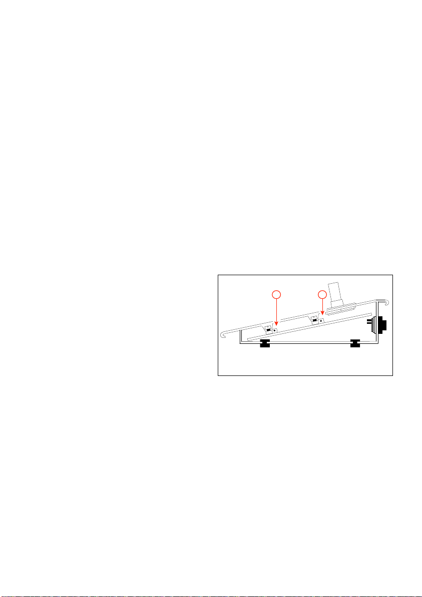
3 It is always preferable to mount power
amplifiers, which generate a certain
amount of heat, above heat sensitive
equipment, like SM30.If however, power
amplifiers must be mounted beneath the
Control Centre, a heat shield should be
installed above them. This is necessary to
deflect the hot air currents, which could
otherwise cause instability in the SM30
microprocessor controlled units.
5.5 Connecting amplifiers
The SM30 system is intended for use with 2
separate amplifiers, or two separate channels
of a multi channel amplifier. One channel
will handle the ‘call’ signal, and the other
channel will amplify the ‘music’ signal. This
allows the music signal to continue,
uninterrupted, when a call is made to other
loudspeaker zones. It is possible to use only
1 amplifier channel for both the ‘calls’ and
‘music’ signal. This has the disadvantage
however, that any music playing will be
interrupted whenever a call is made,
regardless of the zone(s) to which the call is
routed. Though the SM30 system will work
with any line level input amplifier, the
amplifiers from the Philips SQ45 range have
been specifically designed to take the greatest
advantage of the functions of SM30.
One Channel System (fig.5.5.2)
When using a single amplifier system, the
following steps must be taken:
1 The ‘Call’ and ‘Music’ outputs of the
Line Output Module should be
connected to their respective ‘Call’ and
‘Music’ inputs on the SQ45 amplifier.
The relay on the Line Output Module
will switch the active input of the SQ45
amplifier from music to call.
See the relevant SQ45 amplifier
Instructions For Use for details of this
function.
2 The output of the amplifier has to be
connected to the ‘Call’ input on the
‘Mate-N-Lok’ on the SM30 Zone Relay
Module.
3 Refer to Installer Program step 9 to
program this function.
As previously stated, zones with music will
be interrupted for as long as a call to any
other zone(s) lasts.
Rack Mounting
If the amplifier(s) and SM30 are mounted in
a rack unit, and an ‘earth loop’ occurs
(evident by a 50 or 60 Hz hum through the
loudspeakers) follow the Instructions For
Use given with the SQ45 amplifier for
details of earthing the units.
Two Channel System (fig.5.5.1)
Connections of SM30 to two amplifiers, or
two channels of a Philips SQ45 amplifier:
1 Connect both the ‘Call’ and ‘Music’
outputs of the Line Output Module, to
the separate ‘Call’ inputs of the SQ45
amplifier(s).
2 Connect the outputs of the amplifiers
(with two core loudspeaker cable) to their
respective ‘Call’ and ‘Music’ inputs on the
‘Mate-N-Lok’ connector on the Zone
Relay Module of the SM30.
15
Page 18

3
1
C
4X
SQ45
C
13
SM30
Fig. 5.5.1 - Two channel system
16
Page 19

3
1
SQ45
C
1
SM30
Fig. 5.5.2 - One channel system
17
Page 20

6 CALL STATION
(CST) LBB 9568
Redial function (fig.6.1I)
Repeats the last zone selection.
The SM30 Call Station presents the
operator with a logical, comprehensive, and
easy to use method of routing and
broadcasting calls, announcements, and
music. Since each Call Station Input
Module will accept two Call Stations, SM30
will accept up to 6 Call Stations in total.
Electret condenser microphone
The high quality phantom powered
microphone with built-in bass rolloff filter
(fig.6.1L) gives clear voice reproduction,
even in difficult acoustic environments.
Built-in Compressor
Helps to keep the audio output level of the
Call Station constant, even in situations
where the operator’s speech volume level
changes radically. The amount of compression is dependent on the Microphone preamplifier gain setting: the higher the gain
setting, the greater the amount of compression, and therefore the greater the effect on
the microphone signal (see paragraph 6.3).
Balanced Line Level output
Allows Call Stations to be located up to
1000 metres from the Control Centre.
6.1 Operating controls
Numeric Keypad (fig.6.1J)
Allowing individual selection of up to 18
loudspeaker zones by typing in the zone
number. Each Call Station can be
programmed with a priority status, attention
tone and pre-recorded message. These
become operational whenever the keypad is
used to route a call. (See chapter 14 for
programming details).
Zone Selection Indicator (fig.6.1B)
Each zone has its own LED which is
illuminated when the zone is selected. When
the call is completed the LEDs will be
extinguished.
Function Keys (fig.6.1K)
The 4 function keys are to be programmed
with priority; alarm and attention tones;
pre-recorded messages; routing to loudspeak-
er zones; and Control Relay activation. The
alternative functions of these keys include:
music volume up/down; music source
selection; music mute; and independent
Control Relay switching or toggling (see
chapter 14 for programming details). Using
the Function Keys to make a call is done in
the same way as using the Keypad. The
main difference being that instead of the
operator selecting the zones using the
Numeric Keypad, the Function Keys route
the call to a pre-programmed selection of
zones. This of course saves a great amount of
time when an operator has to frequently call
the same selection of zones, or when an
“ALL CALL” must be made in emergencies.
Each Function Key may be programmed to
carry out a totally different task.
Key F1 can be programmed to route a low
priority call, preceded by an attention tone,
to several, frequently used, loudspeaker
zones.
Key F2 could be programmed to route an
alarm tone, followed by a pre-recorded
evacuation message, to all loudspeaker zones
(an “ALL CALL”).
Key F3 could be used to mute the music
signal.
Key F4 could be used to toggle a Control
Relay on and off, switching a warning lamp,
illuminated notice, etc..
18
Page 21

NOTE: If a Function Key and the Keypad
are both selected to activate a call, the last
selection will always have precedence,
cancelling any other selection.
During Installer programming a program is
available to prevent the user of the Call
Station from addressing specific zones
selected via the keypad (see program
14.3.12).
Function Key LED (fig.6.1A)
Whenever a Function Key is pressed the
LED illuminates, together with any Zone
Selection Indicators activated by the routing
of the Function Key. When the call is
completed the LEDs will be extinguished.
‘Press-To-Talk’ Key (fig.6.1H)
Activates a call after the zones have been preselected using the Key Pad or Function Key.
The way in which a call is executed, and
how the ‘Press-To-Talk Key’ is used, depends
on the type of signal and/or message with
which the Key Pad, Function Key, or
Microphone is programmed.
■ Call without signal or message:
Will stop when the ‘Press-To-Talk’ Key is
released.
■ Call with attention signal and/or non-
repeating message:
Will stop when the ‘Press-To-Talk’ Key is
released.
■ Call with attention signal and repeating
pre-recorded message:
The message and/or signal cycle will
continue after the ‘Press-To-Talk’ Key is
released. The cycle can be stopped by
pressing the ‘Press-To-Talk’ Key a second
time.
If this is done during the attention signal,
the call stops immediately.
If the message is playing, the call will stop
at the end of the message.
■ Call with alarm signal:
The alarm signal will continue after
release of the ‘Press-To-Talk’ Key.
It can be stopped by pressing the ‘PressTo-Talk’ Key a second time.
Busy and wait/talk LEDs
(fig.6.1F and 6.1G)
Advise the operator whether a call may be
activated, the status of the call, and whether
any other calls are active.
The red ‘BUSY’ LED flashing means that
another call is in progress.
The red ‘BUSY’ LED illuminated constantly
indicates that the call has been blocked by
another call with a higher priority.
In its ‘WAIT’ state, the green LED flashes,
indicating that the call is accepted, and the
attention tone or pre-recorded message is
being broadcast.
The green LED illuminates constantly
(‘TALK’) when the tone or message finishes
and the processor switches on the
microphone for the call to proceed.
A
F1
4
F2
F3
1- 0 #
F4
L
K
123
5
789
J
B
C
D
E
F
6
PHILIPS
PHILIPS
I
G
H
Fig. 6.1 - Call Station
19
Page 22
6.2 Installation
A
B
Loudspeaker Zone Template
A paper template is provided, on which the
names of the loudspeaker zones can be
written. The template has a detachable blank
section at the bottom, allowing it to be used
in a typewriter.
To mount the template in the Call Station,
first remove the right hand side cheek
(fig.6.1D), by unscrewing the two screws in
its side (fig.6.1E), and the one screw located
in the bottom. The plastic template cover
(fig.6.1C) can now be slid out. Place the
(type) written template in position over the
zone LEDs (having first torn off its blank
perforated panel), and carefully slide the
plastic template cover back in place.
Connection to Control Centre
Between the Call Station and the Call
Station Input Module (see chapter 7.1) the
following cabling is needed::
■ a shielded twisted pair for audio and
power transport;
■ a twisted pair for data transport.
When the copper diameter of each wire is
not less than 0.75 mm2 the length of the
cable can be up to 1000 meters for proper
functioning.
Microphone Preamplifier Gain Preset
should only be used for setting the
amount of compression, not for lining up
the Call Station output with the rest of
the SM30 System. See ‘Built-in
Compressor’ earlier in this chapter.
LED Intensity Preset
With the right hand side cheek removed, it
is possible to gain access to the LED
intensity preset.
To compensate for various local lighting
conditions, the illumination intensity of the
LEDs can be adjusted. Turning the
potentiometer (fig.6.2A) to the right
increases the intensity.
With the template and its cover in position,
and the microphone volume and LED
intensity adjusted, replace the right hand
side cheek.
Fig. 6.2 - CST adjustments
6.3 Adjustments
Microphone Pre-amplifier Gain Preset
With the right hand side cheek of the Call
Station removed, the microphone
preamplifier’s gain can be preset. Turning the
potentiometer (fig.6.2B) to the right
increases the amount of gain. To obtain
nominal 1 Volt output level, the gain can be
preset from 84 to 114 dB SPL.
NOTE: The Call Station Input Modules
also have input gain presets. The
6.4 Using the Call Station
Using the Keypad to make a Call
1 To route a call to one or more
loudspeaker zones, simply type in the
number of each desired zone using the
numeric keypad. Numbers ‘1’ to ‘9’ allow
single digit numbers to be entered,
number ‘1-’ is for tens, and ‘0’ is the
second digit in the number 10. For
instance, to route a call to zones 7, 10,
and 15, type in: 7, then 1-, then 0; then
20
Page 23

1-, then 5. As stated earlier, the Zone
Routing Indicator LEDs for these zones
will be illuminated.
2 If the red ‘BUSY’ LED is flashing, this
means that another call is in progress. If
the other call has lower priority than your
call, pressing your ‘PRESS TO TALK’
key will abort the other call.
If the other call has a higher priority, your
call will not be accepted and you will
have no affect on the other call.
3 If neither the ‘BUSY’ or ‘ WAIT/TALK’
LEDs are illuminated, press and hold
down the ‘PRESS TO TALK’ key.
4 If an attention tone has been
programmed to precede a call, the green
‘WAIT/TALK’ LED will flash until the
tone has finished. When the LED stops
flashing, the microphone is activated and
then you may begin to speak.
If your call is interrupted by a call with a
higher priority, the red ‘BUSY’ LED will
illuminate to tell you that your call is no
longer being heard.
The call should then be aborted and tried
again when no LEDs are illuminated.
Pressing the ‘REDIAL’ key will
automatically reselect the zones which
were last selected, eliminating the need to
type them in again.
5 When the call is finished, release the
‘PRESS TO TALK’ key, and the system
will return to its idle mode, ready for the
next call.
Using the Function Key to make a Call
Using the Function Key to make a call is
done in the same way as using the Keypad.
The main difference being that instead of
the operator selecting the zones using the
Numeric Keypad, the Function Keys route
the call to a pre-programmed selection of
zones.
This of course saves a great amount of time
when an operator has to frequently call the
same selection of zones, or when an “ALL
CALL” must be made in emergencies. As
previously described, whenever the function
key is pressed its Function Key LED
illuminates, along with any Zone Selection
Indicators activated by the routing of the
Function Key. When the call is completed
the LEDs are extinguished.
21
Page 24

7 CALL STATION INPUT MODULE
1
2
2
1
2
LED Data
Key Data
LBB 1283
1
4
2
3
5
}
(CSM) LBB 1283
Each Call Station Input Module allows two
SM30 Call Stations to be connected to the
Control Centre. SM30 will accept up to 3
Call Station Input Modules and/or
Microphone Input Modules in total.
7.1 Installation
Mounting in the Control Centre
The Call Station Input Modules must be
located in the Control Centre slots E, D,
and/or C, as indicated in fig. 5.1.
The number designated to a Call Station by
the microprocessor is dependent on the slot
in which the module is located.
If, for instance, only one Call Station Input
Module is used in a system, and that module
is located in slot E, then the two Call
Stations plugged into the module would be
numbered 1 and 2.
If the same module were plugged into slot
D, then the Call Stations would be
numbered 3 and 4.
If plugged into slot C, the Call Stations
would be numbered 5 and 6.
This regardless of the fact that they are the
only Call Stations in the system.
DIN plug.
The DIN connections, viewed from the
solder side of the cable plugs, are illustrated
in fig.7.
7.2 Adjustments
Volume Level Controls
The 2 front panel controls are input volume
level controls, used for “lining up” the
volume level of the Call Station microphone
with the rest of the SM30 signal sources
(microphones, attention signals, background
music players, etc.).
Since the strength of each person’s voice
differs, set each volume level “by ear” so that
a clear, comfortable listening level, which is
in balance with the other amplified signals,
is attained.
REMARK: Reducing the gain by means of
the module volume level controls means
that it is no longer possible to get the full
volume level output from the connected
SQ45 amplifiers.
Connection of Call Stations
The design of SM30 allows a single cable,
up to 1000 metres long, to be used to
connect a Call Station to one of the Input
Module’s sockets. This cable has two
screened wires, plus two twisted wires. The
screened wires carry the audio signal and
Call Station phantom powering, and the
twisted wires carry the control signal.
Terminate the cable at the side of the Call
Station with a lockable 5-pole 180° female
DIN socket, and at the side of the Input
Module with a lockable 5-pole 180° male
Fig. 7 - CSM
22
Page 25

8 MICROPHONE INPUT MODULE
1
1
2
2
LBB 1282
1
4
2
3
5
2
Microphone
Remote on/off
1
2
Line level
Flat response
1
2
1
2
Bass cut
Switch positions
Microphone
(MIM) LBB 1282
Each Microphone Input Module allows two
electret microphones or two dynamic
microphones to be connected to the SM30
Control Centre.
SM30 will accept up to 3 Microphone Input
Modules and/or Call Station Input Modules
in total.
8.1 Operation
Remote Switching Function
SM30 makes use of the remote switching
facility of certain Philips electret
microphones and dynamic microphones.
This switch is used to activate calls
originating from the microphone, including
all of the programmed functions available
(priority, routing, attention signals, etc.) (See
chapter 14 for programming details).
Line Input Facility
By changing a switch, mounted on the
circuit board of the module (one double
switch block for each channel), it is possible
to connect a line level input source, instead
of a microphone. In its up position, switch 1
on the switch block is set for Microphone
(the default). In its down position, it is set
for Line Level Input. It is possible to
distribute this line source by means of
contacts on the Contact Input Module 1.
switch block as the Line Input switch, the
Bass Cut can be de-activated.
In its up position, switch 2 on the switch
block is set for Bass Cut (the default).
In its down position, it is set for Flat
response.
8.2 Installation
Mounting in the Control Centre
The Microphone Input Modules must be
located in the Control Centre slots E, D,
and/or C, as indicated in fig.5.1.
The number designated to a Microphone by
the microprocessor is dependent on the slot
in which the module is located.
If, for instance, only one Microphone Input
Module is used in a system, and that module
is located in slot E, then the two
Microphones plugged into the module
would be numbered 1 and 2.
If the same module were plugged into slot
D, then the Microphones would be
numbered 3 and 4.
If plugged into slot C, the Microphones
would be numbered 5 and 6.
This regardless of the fact that they are the
only Microphones in the system.
Bass Cut Facility
In noisy environments the operator often
has to speak very close to the microphone,
which exaggerates the bass frequencies of the
microphone.
A bass-cut facility is available to reduce the
bass, helping the call to be clearly heard.
On delivery, the bass-cut is active. By
changing switch 2, located on the same
Fig. 8 - MIM
23
Page 26

Connection of Microphones
The design of SM30 allows a single cable to
be used to connect a Microphone to one of
the sockets of the Microphone Input
Module.
This cable has two screened wires, plus two
unscreened wires.
The screened wires carry the audio signal
and phantom powering, and the unscreened
wires are connected to the remote switch of
the microphone. Terminate the cable at side
of the microphone with a lockable 5-pole
180° DIN female socket, and at the side of
the Input Module with a lockable 5-pole
180° DIN male socket.
The DIN connections, viewed from the
solder side of the cable plugs, are illustrated
in fig.8.
8.3 Adjustments
Gain Control Potentiometers
The 2 front panel controls are input gain
controls, used for “lining up” the volume
level of the microphone with the rest of the
SM30 signal sources (Call Stations, attention
signals, pre-recorded messages, background
music players, etc.). Because the strength of
each person’s voice differs, set each gain
control “by ear” so that a clear, comfortable
listening level is attained, which is in balance
with the other amplified signals.
9 CONTROL INPUT MODULE
(CIM) LBB 1284
Each Control Input Module allows eight
remote switches to be connected to the
Control Centre. Up to 3 Control Input
Modules can be located in the SM30
Control Centre allowing a total of 24
remote switches to be used, but resulting in
less of Call Station Input Modules and
Microphone Input Modules. When a remote
switch closes the normally open circuit, the
Control Input circuit senses this, and the
SM30 microprocessor carries out a series of
actions.
9.1 Operation
All Control Inputs
Each Control Input can be programmed to
carry out SM30 switching functions,
including:
■ Activation of one of the SM30 attention
or alarm signals.
■ Activation of a pre-recorded message.
■ Routing of the above listed signals to
loudspeaker zones, after giving the call a
programmed priority status.
Inputs 1 to 8 of first CIM (fig.5.1F).
Apart from the above listed functions, inputs
1-4 may be given an alternative function.
This allows remote control of the Music
Function Keys, located on the front panel of
the SM30 Control Centre:
Input 1 Music volume up activation
Input 2 Music volume down activation
Input 3 Music mute on/off
Input 4 Music source selection
Input 5-8Apart from the normal switching
functions, inputs 5-8 may be
programmed to activate Control
Relays, which can be used to start
24
Page 27

remote equipment, activate
1
2
3
4
5
6
7
8
Comm on ret urn
LBB 1284
Individual
return
signalling/warning lamps, etc..
Input 1-8Apart from the normal functions,
inputs 1-8 can be programmed to
distribute an external audio source
connected to a Microphone Input
Module to zone 1-36 preceded
with an attention signal and/or
pre-recorded message. in that case
relay 4 of the Control Relay
Module of the basic frame is used
to start the audio source.
Direct routing
Control inputs 1-6, 1-12, or 1-18 can be
programmed to route a call or music directly
to loudspeaker zones 1-6, 1-12, or 1-18.
9.2 Installation
Mounting in the Control Centre
The Control Input Modules must be located
in the Control Centre slots F, E, and/or D,
as indicated in fig.5.1.
The numbers designated to Control Inputs
by the microprocessor are dependent on the
slot in which their module is located. If only
one Control Input Module is used in the
system, that module should be located in
slot F, then the eight Control Inputs are
numbered 1 to 8.
If another module were plugged into slot E
instead of F, then the Control Inputs are
numbered 9 to 16. Accordingly, slot D will
carry inputs numbered 17 to 24.
Note should be taken of the paragraphs
referring to Inputs 1-4 and Inputs 5-8 when
planning the location of the Control Input
Module(s) in the Control Centre.
Wiring control inputs
Each Control Input Module is supplied with
a plug-in, 16 terminal, screw connector
block.
The remote switch wires are connected to
the screw terminals, which are marked in
pairs 1 to 8.
The great advantage of the connector block
is that if, for some reason, the SM30
Control Centre has to be removed, the block
has simply to be unplugged and the wires
remain intact.
This avoids the tedious and risky business of
rewiring the blocks in their original
configurations.
9.3 Programming
Control inputs can be programmed for
different facilities:
■ normal Call activation (see installer
programming par.14.7 menu 8 ‘Store
Hardware’);
■ remote music control or Control Relay
switching (see user programming par.14.3
menu 3 ‘Control Inputs’);
■ direct zone routing (see installer
programming par.14.7 menu 13 ‘Direct
Routing’).
Fig. 9 - CIM
25
Page 28

10 RECORDED MESSAGE MODULE
(RMM) LBB 1285
A unique feature of SM30 is its Recorded
Message Module, which allows up to 4
individual messages to be recorded, and
played back as desired.
The recording is digitally stored in memory
chips, ensuring that the quality will not
deteriorate for as long as the message is in
memory. Messages will remain in memory so
long as the power is turned on. If SM30 is
switched off, a backup battery will enable
the messages to remain intact for up to 30
days. The maximum total recording time is
65 seconds, and up to 4 messages of varying
durations may be recorded, so long as the
sum of the durations does not exceed the
maximum recording time. SM30 can be
programmed so that a message is played
back either alone, or preceding a call
(following an attention signal, if desired).
Playback can be activated by a Control
Input; a microphone remote switch; or a
Call Station Keypad or Function Key.
Automatic Gain Control
A limiter ensures that, even though the
microphone signal fluctuates severely, the
message is recorded at a fairly constant level.
This, however, is not an overload protection
device. The operator should speak at about
30 cm from the microphone, with a normal
speaking voice, to ensure that the input is
not overloaded.
Headphone Monitoring
A headphone socket (fig.10A) allows the
recorded messages to be monitored, both
during and after recording, without them
having to be amplified via the system. This
is especially useful, during a recording
session, for checking that a recording is
being, or has been, successfully made.
10.1 Installation
Mounting in the Control Centre
The SM30 Control Centre provides space
for one Recorded Message Module, which
must be located in slot A (see fig.5.1).
Microphone Input
The microphone input (fig.10I), terminated
with a 5-pole 180° DIN socket, provides
phantom powering, so that either a Philips
electret microphone or a dynamic
microphone may be used to record the
messages. (See fig.8 for Microphone Input
plug wiring details).
10.2 Adjustments
Output Volume Control
A volume control potentiometer (fig.10B)
on the front panel allows the output volume
level to be “lined up” with other SM30
signal sources (attention signals,
microphones, music sources, etc.). Turning
the control clockwise increases the volume
level; anti-clockwise decreases the level.
10.3 Recording messages
Clearing the Memory
On delivery of the unit the memory of the
module must be cleared, before any messages
can be recorded, as following:
■ Slide the Message Selection switch
(fig.10C) to position ‘1’.
■ Move the Function switch (fig.10H) to
the top position ‘record’.
■ Now press the (erase) button (fig.10G).
Both the green Message Present LED
(fig.10E) and the red Record LED
(fig.10F) will illuminate for as long as the
button is pushed.
When recording for the first time, or when
the memory of the module has been cleared,
it is important to record messages in
26
Page 29

E
D
C
B
F
G
H
I
A
LBB 1285
Fig. 10 - RMM
numerical order, commencing with message
1.
Recording a Message
■ To record the first message, slide the
Message Selection switch to position ‘1’.
■ Next move the Function switch to the
top position ‘record’.
■ To commence recording, press the
Start/Stop button (fig.10D). The red
Record LED will now illuminate and
begin to speak into the microphone.
■ Immediately after the message has been
spoken, push the Start/Stop button once
more to stop the recording. The green
Message Present LED will now
illuminate to advise that a message is
present at that position.
■ The message can now be checked by
moving the Function switch to its middle
(monitor) position and listening through
a set of headphones.
When the message is being replayed,
either through headphones, or through
the system, the green Message Present
LED will flash.
■ If the recording is satisfactory, either
move the Message Selection slide switch
to position ‘2’, and follow the above steps
to record the second message.
With the Function switch in its lowest
(system) position, the recording is ready to
be played back via the system when desired.
Recording over an Existing Message
When a message is recorded, its time
duration is stored in memory. When a new
message is recorded over an existing one, the
new message will automatically be the same
length as the original. The red Recording
LED will illuminate for the original
duration of the message, and extinguish at
the end of that time, indicating that the
recording is finished. The recording cannot
be terminated by the Start/Stop switch
when recording over an existing message.
REMARK: If the new message is too long,
it will be cut off before it is finished. If it
is too short, there will be a silence at the
end of the message, for the remaining
time, before the system can continue with
its next function.
If this is unworkable, the messages which are
currently in memory should be erased, and
all of the messages should be re-recorded.
(See paragraph ‘Clearing Memory’).
Safety Features
With the Function switch in its lowest
(system) position, the Message Select switch
and the Start/Stop button and Erase button
will be inoperative.
The Erase button will only become
operative when the Message Select switch is
in position ‘1’, and the Function switch is in
the top (record) position.
27
Page 30

The Function switch must be in its lowest
(system) position for messages to be replayed
through the system.
When the Function switch is in its top
(record) or middle (monitor) position,
SM30 will not be able to use the Recorded
Message function, and the messages already
recorded will not be accessible to the user.
An ERROR warning will be seen on the
display of the Control Centre, indicating
that the Message Module is not in its
‘system’ mode.
If the Function switch is in the top (record)
position, and the Message Selection switch
is moved to a position where a message is
already recorded, the green Message Present
LED illuminates to warn that a message is
present at that position.
Remote Location Recording
Because the Record and Monitor functions
are independent of the SM30
microprocessor, the unit may be taken out of
the Control Centre, and transported to a
remote location.
There, with the aid of suitable power
supplies of +5 V and +35 V, the module
may be used to record the messages in a
more suitable/convenient recording
environment. Refer to the service
documentation of SM30 how to make the
connections.
11 MUSIC INPUT MODULE
(MUM) LBB 1286/10
The ability of SM30 to play music, which is
uninterrupted, even though the system is
handling a call routed to other loudspeaker
zones, is an important feature of the system.
To make best use of this feature, Philips have
developed the Music Input Module. The
module enables 3 independent music sources
to be connected to the Control Centre.
11.1 Installation
Mounting in the Control Centre
One Music Input Module may be installed
in the Control Centre.
This module must be located in slot B as
illustrated in fig.5.1.
Music Source Inputs
The module provides 3 sets of double cinch
sockets (fig.11A) for connection of the
music sources. The double sockets allow
stereo signal sources to be connected, using
standard double cinch/ cinch Hi-Fi cables.
The stereo signal is mixed to mono in the
module. A mono signal (e.g. from a radio
tuner) should simply be plugged into either
one of the two sockets.
11.2 Adjustments
Individual Input Volume Controls
Three potentiometers (fig.11B)
corresponding to the three inputs, give the
user/installer the capability of setting the
input volume levels of each source
independently.
Adjust the source signal levels so that when
the operator selects a different source, no
great change in music volume level occurs.
28
Page 31

Output Treble and Bass Tone Controls
A
B
C
D
LBB 1286
Treble and Bass potentiometers (fig.11C and
D) provide tone control facilities for the
output of the module.
In the vertical (12 o’clock) position, the
signal is unaffected. Turning the control
clockwise increases the level of the relevant
treble or bass frequency range by up to 10
dB. Turning it anticlockwise decreases the
frequency range volume level by up to 10
dB.
Front panel controls of Control Centre
(fig.4.1E)
To allow the operator to control the music
sources, four Music Function Keys are
provided on the front panel of the SM30
Control Centre. These keys allow the
operator to select the music source; alter the
music volume level up or down; and mute
the music signal. When either the ‘Music
Volume up’ or ‘Music Volume down’ key on
the Control Centre is pushed, the output
volume of the Music Input Module changes
in steps of ‘3’ over a range of ‘00’ to ‘99’.
Each step of 3 represents 2 dB, with ‘99’
equalling 0 dBV. Any, or all of these four
functions can also be remote controlled via
the Function Keys on the Call Station.
11.3 Programming
Software routing to zones
For details of routing the music signal to
specific loudspeaker zones see user
programming 14.3.1 step 19 ‘F-key music
routing’ and menu 4 ‘Music routing’ and
installer programming 14.7 menu 13 ‘Direct
routing’.
Display music source status
The current music source and the output
volume level can be seen on the bottom line
in the display when SM30 is in its normal
‘run’ mode. See installer programming
14.7.6 ‘Music Input text’ to alternate the
names for sources 2 and 3 for showing on
the display.
Fig. 11 - MUM
29
Page 32

12 ZONE RELAY MODULE
(ZRM) LBB 1287
The SM30 system is intended for use with 2
separate amplifiers, or two separate channels
of a multi channel amplifier. One channel
will handle the ‘Call’ signal, and the other
channel will amplify the ‘Music’ signal.
This allows the music signal to continue,
uninterrupted, when a call is made to other
loudspeaker zones.
Both the Call and Music signals are
processed via SM30, and are available on the
output on the Line Output Module. The
signals are then amplified by their separate
power amplifiers, and the amplified signals
return to SM30, via the inputs of the Zone
Relay Module.
The SM30 software uses the relays of the
Zone Relay Modules to route the separate
signals to their relevant loudspeaker zones.
Each Zone Relay Module is capable of
routing the amplified Call and Music signals
to 6 separate loudspeaker zones. Up to 3
units may be installed in the Control
Centre, giving SM30 the capacity to route
the signals to 18 loudspeaker zones.
fact that they are the only loudspeaker zone
outputs in the system. This should be taken
into consideration when planning the
location of the Zone Relay Module(s) in the
Control Centre.
Terminations
The module is fitted with 2 ‘Mate-N-Lok
connectors. All wiring is done in the plugs
provided with the module, which means
that the wiring itself remains intact if SM30
is ever removed for servicing, etc.. The top
connector (fig.12.1B) is the input connector.
The outputs of the amplifiers are plugged
into the right row of the sockets.
The centre row of 4 sockets are used for
linking the module to the next Zone Relay
Module. The bottom connector (fig.12.1A)
feeds the routed outputs to the 6
loudspeaker zones. Fig.12.2 and fig.12.3
show how to connect the Mate-N-Lok
connectors and illustrates several possibilities
for configuring amplifier connections, some
of which are briefly described below.
12.1 Installation
Mounting in the Control Centre
Up to three Zone Relay Modules can be
installed in the Control Centre, in slots G,
H, & I, as illustrated in fig.5.1.
The numbers designated to Loudspeaker
Zones by the microprocessor are dependent
on the slot in which the Zone Relay Module
is located. If, for instance, only one Zone
Relay Module is used in a system, and that
module is located in slot I, then the six
loudspeaker zones would be numbered 1-6.
If the same module were plugged into slot
H, instead of I, then the loudspeaker zones
would be numbered 7-12, regardless of the
B
A
LBB 1287
Fig. 12.1 - ZRM
30
F3
F2
F1
Page 33

12.2 Coupling Zone Relay Modules
When more than 1 Zone Relay Module is
used in a system, the inputs of the modules
may be linked together (fig.12.2), so that the
same amplifier(s) can feed up to 18
loudspeaker zones. This is done by making
short linking wires, fitted with Mate-N-Lok
connector pins at each end. One end is
pushed into one of the centre row of
termination sockets in the first ‘Input’ MateN-Lok connector plug (I).
The other end is pushed into the
corresponding right row of termination
sockets in the second ‘Input’ Mate-N-Lok
connector plug (H), and if applicable also
connected to the third ‘input’ Mate-N-Lok
connector plug (G).
12.3 Multiple Amplifier Configurations
In large systems, comprising many
loudspeakers, it may be necessary, because
the large amount of amplifier power
required exceeds the power available, to use
extra power amplifiers. This can be done in
one of several different ways:
- Unlinked multiple modules.
Separate amplifiers may be used to feed each
Zone Relay Module. This enables each
amplifier to be dedicated to 6 specific zones.
- Module input splitting
(fig.12.3).
The Zone Relay Module provides the
possibility of connecting more amplifiers to
a single module, so that each amplifier feeds
fewer loudspeaker zones. Three miniature
fuses, link the centre and left rows of sockets
of each of the Call, Music, and (common)
Ground sockets of the amplifier input
connector (fig.12.1).
If one of the fuses is removed, the amplifier
connected to the corresponding (right)
socket will only feed sockets 1-4 of the LS
output connector.
Another amplifier, connected to the
corresponding left socket, will then feed only
sockets 5 and 6 of the LS output connector.
G
3621
4
5
7
89
101112
15
14
362
5
13
1
4
789
101112
16
17
18
Fig. 12.2 - Coupling zones
H
3
2
1
4
5
6
7
8
9
101112
9
8
2
3
5
6
8
9
7
1
4
7
101112
10
11
12
I
3621
4
5
78
9
101112
3621
4
5
78
9
101112
CALL
MUSIC
LS GROUP
3
2
1
4
5
6
31
Page 34

Fig. 12.3 - Input splitting
X
X
X
CALL ( ZONE 1,2,3,4 )
MUSIC ( ZONE 1,2,3,4 )
CALL ( ZONE 5,6 )
MUSIC ( ZONE 5,6 )
362
1
4
5
7
8
9
101112
3
2
1
4
5
6
LS GROUP
I
362
1
4
5
7
8
9
101112
2
4
Fig. 13 - CRM
6
8
10
LBB 1288
1
3
5
7
9
1112
13 CONTROL RELAY MODULE
(CRM) LBB 1288
The Control Relay module provides SM30
with a set of switching contacts, which can
be opened or closed (dependent on the
contact, and its terminations) as
programmed by the installer or operator.
Relays 1 to 8 have both make and break
contacts. Relays 9 to 12 have make contacts.
These contacts can be used to start remote
equipment, such as cassette players, message
loggers, etc.; to activate signalling/warning
lamps; to release fire door relays; etc..
13.1 Operation
Relay 1 is reserved for the indication of
microprocessor errors, and cannot be used
for any other function.
Relay 2 is reserved for indication of all other
internal errors (modules and Call Stations),
and cannot be used for any other function.
Relay 3 is dedicated to the ‘Delayed Power
On’ function, but may be used for other
functions if Power On Delay is not required.
The Delayed Power On function is intended
for battery operated systems where, in order
to conserve battery power, the SQ45
amplifier(s) is/are switched on only when a
call is made. It causes a time delay (selectable
from 2-9 seconds) between pressing the Call
Station ‘Press-To-Talk’ key, the Microphone
‘on’ switch or switching-on of a Control
Input and the actual activation of the call.
Both sides of the normal ‘open’ contact of
relay 3 are wired to the switch terminations
on the SQ45 ‘DC Power’ Mate-N-Lok
connector(s). The software causes the relay
contacts to close (‘make’), switching on the
DC power of SQ45. (See the SQ45
Instructions for Use for further details).
Relay 4 is dedicated in case an external
audio source connected to an input of the
32
Page 35

Microphone Input module should be started
with contact 1-8 of the Control Input
Module. See user programming 14.3 menu
item 3.8 ‘Control inputs 1-8’.
Relays 3-12
Relays 3 (or 4 if power-on delay is used) to
12 can be activated by different sources, and
may be used for a number of functions.
Remote Volume Control Overrides
The ‘make’ contacts of Relays 3 to 12 may
be used to activate up to 10 loudspeaker
volume control override relays. These relays,
mounted in the loudspeaker enclosures,
override the volume control setting of the
actual loudspeaker itself. This means that
regardless of the individual ‘music’ volume
setting of each loudspeaker, all the
loudspeakers in a particular zone will work
at full volume when a Call is routed to it.
13.2 Installation
Mounting in the Control Centre
One Control Relay Module is used in
SM30. This must be located in Control
Centre slot J, as indicated in fig.5.1.
Wiring Control Relays
Each Control Relay Module is supplied with
two plug-in, 16 terminal, screw connector
blocks (fig.13). The wires to remote
equipment are connected to the screw
terminals, which are marked in threes 1 to 8
(make and break contacts), and in pairs 9 to
12 (make contact). The great advantage of
the connector block is that if, for some
reason, the SM30 Control Centre has to be
removed, the blocks have simply to be
unplugged and the wires remain intact. This
avoids the tedious and risky business of
rewiring the blocks in their original
configurations.
13.3 Programming
Power-on delay
The Power-on delay function can be
programmed with a time delay of 2-9
seconds (see installer programming 14.7
menu 5 ‘Power-on delay’).
Coupling relays to zones
Each Control Relay is programmable,
‘linked’ or ‘locked’, to a specific Zone Relay,
so that when a call is routed to a loudspeaker zone, the Control Relay linked to it will
activate automatically (see installer programming 14.7 menu 11 ‘Override relays’). The
display will show ‘Z’ for the relays involved.
Activation by Call Station and Function
Keys
Relays 3 (or 4, if power on delay is used) to
12 may be programmed to be activated by
Call Stations, and Function Keys on Call
Stations. Activation by a Call Station
happens whenever a call is made using
Keypad of the Call Station Keypad (see user
programming 14.3 menu 1.7). Activation by
a Function Key happens whenever a preprogrammed Function Key (followed by the
‘Press-To-Talk’ key) is pressed (see user
programming 14.3 menu 1.14).
Activation by Control Inputs
Relays 3 (or 4, if power on delay is used) to
12 may also be programmed to be activated
by Control Input contacts (see user
programming 14.3 menu 3.12). Control
Input contacts 5 to 8 can be programmed to
activate one, or a group of, Control Relay(s).
This means that when the remote switch of
a control input is closed, the programmed
Control Relays become activated (see user
programming 14.3 menu 3.7).
The display will show ‘A’ for the relays
involved.
33
Page 36

14 PROGRAMMING
14.1 Summary SM30 User Programming
program step selection
User password 0
1.1 CALL STATIONS
1.2 - number 1-2, 3-4, 5-6
1.3 - Keypad 0-6, 7-12, 13-18
1.4 - priority number 1-9
1.5 - signal number 00-nn
1.6 - message number 0,1,2,3,4,1R,2R,3R,4R
1.7 - control relay number 4-12
1.8 - Function key number 1,2,3,4
1.9 - Call programming
1.10 - priority number 1-9
1.11 - signal number 00-nn
1.12 - message number 0,1,2,3,4,1R,2R,3R,4R
1.13 - zone number 1-6, 7-12, 13-18
1.14 - control relay number 4-12
1.15 - Remote music up on/off
1.16 - Remote music down on/off
1.17 - Remote music mute on/off
1.18 - Remote music select on/off
1.19 - Remote relay switch on/off
1.20 -control relay number 4-12
1.21 - Remote relay toggle on/off
1.22 - control relay number 4-12
2.1 MICROPHONES
2.2 - number 1-2, 3-4, 5-6
2.3 - priority number 1-9
2.4 - signal number 00-nn
2.5 - message number 0,1,2,3,4,1R,2R,3R,4R
2.6 - zone number 1-6, 7-12, 13-18
2.7 - control relay number 4-12
3.1 CONTROL INPUTS
3.2 - number 1-8, 9-16, 17-24
3.3 - 1 music volume up on/off
3.4 - 2 music volume down on/off
3.5 - 3 music mute on/off
3.6 - 4 music source select on/off
3.7 - 5/8 remote relay switch on/off
3.8 - 1/24 - priority number 1-9
3.9 - signal number 00-nn
3.10 - message number 0,1,2,3,4,1R,2R,3R,4R
3.11 - zone number 1-6, 7-12, 13-18
3.12 - relay number 4-12
4.1 MUSIC ROUTING
4.2 - zone number on/off
34
Page 37

14.2 Introduction
14.2.1 General
Programming is carried out using the keys
on the front panel of SM30 Control Centre.
A password must be keyed in via the
programming keys in order to enter a
Programming mode.
Illuminated LEDs on the front panel
indicate which keys can be used at the
current stage of programming.
The left/right arrow keys are used to scroll
through the main menu in order to move to
a different program, and also to move the
cursor during zone routing and relay
assignment.
The double up/down arrow keys are used to
select tens during attention and alarm signal
programming.
The single up/down arrow keys are used to
scroll through selections within an actual
program, and to select digits 1 to 9 during
attention and alarm signal programming.
Pressing BREAK will always return to the
next higher programming level.
Pressing ENTER will confirm your
selection, storing the information in the
system’s memory.
14.2.2 User Program
The User Program is a limited version
(programming menus 1 up to 4) of the
Installer Program, detachable at the rear of
the book. This program is intended, as its
name implies, to allow the user(s) of the
system to alter priorities, routing, etc. as
their needs change, without having to call in
expert help. The program contains a variety
of items which are dependent upon the
system configuration.
Programs marked * in the program step list
will only appear on the display if the
relevant modules and/or Call Stations are
present in the system. When a module is not
present in the system the relevant program
step will not be shown on the display.
If the system is in normal operation (in its
‘Run’ mode), the display will show:
* SM30 SYSTEM *
XXXXXXXXX YY
If the Music Input Module is present, the
second display line shows XXXXXXXX as
the current music source name, and YY as
the current volume level (marked, in steps of
3, from 00 to 99).
If the Music Input Module is not present,
the bottom line will be empty.
The main menu can always be recognised by
“SELECT PROGRAM:” in the upper line
of the display. Scrolling through the menu
can be done with the left /right arrow keys.
This programming guide assumes that all
possible modules and Call Stations are
present in the system.
14.2.3 User Programming Mode
To enter the User Programming mode, type
the correct password: O > ENTER
The display will show:
* SOFTWARE *
* VERSION x.xx *
After a few seconds the display shows:
SELECT PROGRAM:
CALL STATIONS
This is the first program step in the main
menu.
35
Page 38

SELECT PROGRAM :
CALL STATIONS
SELECT ITEM :
CALL STATION : X
SELECT FUNCTION :
FUNCTION KEY : F1 - 4
SELECT FUNCTION :
KEY PAD
CALLST : X FKEY : X
CALLST : X KEYPAD
PRIORITY : X
MUSIC VOLUME
CALLST : X FKEY : X
1
1
CALL PROGRAMMING
2
3
4
8
9
15
CALLST : X KEYPAD
CALLST : X FKEY : X
SIGNAL : XX
MUSIC VOLUME
CALLST : X FKEY : X
CALLST : X FKEY : X
CALLST : X KEYPAD
CALLST : X KEYPAD
MESSAGE : X
MUSIC MUTE
XX0000 REL : 03
MUSIC SELECT
CALLST : X FKEY : X
CALLST : X FKEY : X
CALLST : X FKEY : X
CALLST : X FKEY : X
CALLST : X FKEY : X
7
6
5
10
11
12
13
14
16
17
18
PRIORITY : X
SIGNAL : XX
MESSAGE : X
XX0000 REL : 03
000000 ZONE : 01
CALLST : X FKEY : X
CALLST : X FKEY : X
RELAY SWITCH
RELAY TOGGLE
CALLST : X FKEY : X
CALLST : X FKEY : X
XX0000 REL : 03
XX0000 REL : 03
20 21
22
23
CALLST : X FKEY : X
MUSIC ROUTING
19
Call Stations
36
Page 39

14.3 User Programming
14.3.1 CALL STATIONS
1.1 Main menu selection
Signal number “00” means: no signal.
If the selected signal number does not exist,
the display will show:
* NOT EXISTING *
SIGNAL : XX
Select from the main menu by means of the
left/right arrow keys:
CALL STATIONS
1.2 Call Station number selection
The cursor will be blinking below the
number of the first Call Station found. The
numbers of Call Stations not present will be
skipped. Selection of another Call Station
can be made using the up/down arrow keys.
1.3 Key Pad Selection
Default is selected the Key Pad of the Call
Station. To program the Function Keys of
the Call Station, select the function key: F1,
F2, F3 or F4 by means of the up/down
arrow keys, and continue with program step
1.8.
1.4 Priority level selection
The display will show the current priority.
Changing the priority level can be done with
the up/down arrow keys. Level 1 is the
lowest; level 9 is the highest priority. (See
chapter ‘System Operation’ for description
of the priority function.)
1.5 Signal number selection
This is the attention or alarm signal that
either precedes a call, or may be used alone.
Signals are selectable using the up/down
arrow keys. Double up/down arrows keys
change the tens, and single arrow keys
change the single numbers.
Pressing any key will return to signal
number selection.
1.6 Pre-recorded Message number
selection
This display will be skipped if the Recorded
Message Module is not present.
The message number can be selected using
the up/down arrow keys.
The sequence of message number selection
on the display is:
0, 1, 2, 3, 4, 1 REPEAT, 2 REPEAT, 3
REPEAT, 4 REPEAT.
“MESSAGE: 0” means: no message. Pressing
BREAK will return to priority level
selection.
See chapter ‘Recorded Message Module’ for
a full explanation, and details of how to
record messages.
1.7 Programming Control Relays
This display will be skipped if the Control
Relay Module is not present in the system.
The current relay programming of Control
relays 1-6 is shown. Shifting the cursor to
the right, further than the last position, will
display the current setting of relays 7-12.
The lower right of the display will show the
relay number which is being indicated by
the cursor. Moving the cursor to a different
relay can be done with the left/right arrow
keys. Relays which are already selected are
indicated by 1, non-selected relays are
indicated by 0. Selecting a relay can be done
with the ‘|’ key. Deselecting a relay can be
done with the ‘O’ key.
37
Page 40

Relay 1 (marked ‘X’) is reserved for the
activation of error indicators, if a processor
failure is detected, and cannot be
programmed for any other function.
Relay 2 (marked ‘X’) is reserved for the
activation of error indicators, if a Call
Station or module failure is detected, and
cannot be programmed for any other
function.
Relay 3 is dedicated to the ‘Delayed Power
On’ function explained in paragraph 5
‘Programming Power On Delay’, but may be
used for other functions if ‘Power On Delay’
is not used. If it is used, the third position
will be marked with an ‘X’ in the display.
Relay 4-6 (marked ‘O’) are not selected.
If Control Relays are to be used for
alternative functions, refer to program step
1.15. Pressing BREAK will return to Key
Pad selection.
1.8 Function Key number selection
Selection of the Function Key number can
be made with the up/down arrow keys. The
display sequence is:
KEYPAD, FUNCTION KEY: F1, F2, F3,
F4
1.9 F-key programming selection
Each Function Key on a Call Station can be
used for activation of one of two main
purposes:
■ Call Programming after pressing ENTER.
■ Remote control of the Music and Control
Relay functions to be selected by means
of the left/right arrow keys (see program
step 1.15 and 1.22).
1.10 F-key Priority selection
See program step 1.4.
1.11 F-key Signal number selection
See program step 1.5.
1.12 F-key Pre-recorded Message number
selection
See program step 1.6.
1.13 F-key Call Routing to Zones
The current programmed call routing will be
displayed.
The lower right of the display will show the
zone number which is being indicated by
the cursor.
Moving the cursor to a different zone can be
done with the left/right arrow keys. Shifting
the cursor to the right, further than the last
position, will display the routing of zones 712, if Zone Relay Module 2 is present.
Shifting the cursor to the right again, further
than the last position, will display the
routing of zones 13-18, if Zone Relay
Module 3 is present.
If only Zone Relay Modules 1 and 3 are
present, the routing of zones 13-18 will be
displayed instead of 7-12. On the display,
zones which are already selected are
indicated by 1, non-selected zones are
indicated by 0.
Selecting a zone can be done with the ‘|’ key.
Deselecting a zone can be done with the ‘O’
key.
1.14 F-key programming Control Relays
See program step 1.7.
Programming of alternative Function Key
Each Function Key on a Call Station can be
used for one of two main purposes.
Instead of selection of Call Programming
(program step 1.9) , each Function Key can
38
Page 41

also be programmed with one of six more
functions. The ‘music’ functions are only
available if the Music Input Module is
present.
The ‘relays’ functions are only available if
the Control Relay Module is present.
The Function Key LED on the Call Station
indicates whether the relays are on or off.
Scroll with the up/down arrow keys to select
the alternative function.
1.15 F-key Music volume up
Pressing the assigned Function Key on the
Call Station increases the music volume
level.
broadcasting music. However, adding or
deleting of zone numbers is possible by
means of the numeric keypad of the Call
Station. Pressing the F-key again will store
the new zone selection into the memory
while the previous selection will be erased.
1.20 F-key Relay switching selection
This function allows the selected relays to be
active only while the Function Key is
pressed.
Already assigned relays are indicated by ‘A’
and can not be used.
The function key LED indicates whether the
relays are on or off.
1.16 F-key Music volume down
Pressing the assigned Function Key on the
Call Station decreases the music volume
level.
1.17 F-key Music on/off
Pressing the assigned Function Key on the
Call Station switches on/off the music.
1.18 F-key Music source select
Pressing the assigned Function Key on the
Call Station allows selecting one of three
music sources.
1.19 Music routing
This program step provides music routing
programming of F-keys by means of the
numeric keys on the Call Station.
After pressing the assigned F-key on the Call
Station, the red and green LEDs illuminate
to indicate that this F-key has been
programmed as a music routing F-key. The
zone LEDs show the zones that are currently
1.21 Programming Control Relays
See program step 1.7
1.22 F-key Relay toggling selection
This function allows the selected relays to be
switched on when the Function Key is
pressed the first time, and switched off when
the key is pressed a second time.
Already assigned relays are indicated by ‘A’
and can not be used.
The function key LED indicates whether the
relays are on or off.
1.22 Programming Control Relays
See program step 1.7
39
Page 42

2 MICROPHONES
2.1 Main menu selection
Select from the main menu by means of the
left/right arrow keys:
MICROPHONES.
2.2 Microphone number selection
Pressing ENTER will show the number of
the first microphone found in the system.
The system can detect the presence of the
Microphone Input Module, but not whether
a microphone is connected to that
Microphone Input Module. So it is, in
principle, possible to program microphones
on an Microphone Input Module even if
those microphones are not present. Another
microphone number can be selected using
the up/down arrow keys.
2.3 Priority level selection
The display will show the current priority.
Changing the priority level can be done with
the up/down arrow keys.
Level 1 is the lowest; level 9 is the highest
priority. See chapter ‘System Operation’ for
description of the priority function.
2.4 Signal number selection
This is the attention or alarm signal that
either precedes a call, or may be used alone.
Signals are selectable using the up/down
arrow keys. Double up/down arrow keys
change the tens, and single up/down arrow
keys change the single numbers. Signal
number “00” means: no signal. If the
selected signal number does not exist the
display shows:
* NOT EXISTING *
SIGNAL: XX
2.5 Pre-recorded message number
selection
This display will be skipped if the Re-corded
Message Module is not present.
Message number can be selected using the
up/down arrow keys.
The sequence of message number selection
on the display is:
0, 1, 2, 3, 4, 1 REPEAT, 2 REPEAT, 3
REPEAT, 4 REPEAT.
“MESSAGE: 0” means: no message.
Pressing BREAK will return to ‘priority level
selection’.
See chapter ‘Recorded Message Module’ for
a full explanation, and details of how to
record messages.
2.6 Call Routing to Zones
The current programmed call routing will be
displayed. On the display, zones which are
already selected are indicated by 1, nonselected zones are indicated by 0.
The lower right of the display will show the
zone number which is being indicated by
the cursor.
Moving the cursor to a different zone can be
done with the left/right arrow keys. Shifting
the cursor to the right, further than the last
position, will display the routing of zones 712, if Zone Relay Module 2 is present.
Shifting the cursor to the right again, further
than the last position, will display the
routing of zones 13-18, if Zone Relay
Module 3 is present.
If only Zone Relay Modules 1 and 3 are
present, the routing of zones 13-18 will be
displayed instead of 7-12.
Selecting a zone can be done with the ‘|’ key.
Deselecting a zone can be done with the ‘O’
key. Pressing BREAK will continue with
programming the control relays.
40
Page 43

SELECT PROGRAM :
MICROPHONES
SELECT I TEM :
MICROPHO NE : X
MICROPHO NE : X
MICROPHO NE : X
PRIORITY : X
SIGNAL : XX
2
4
1
2
3
MICROPHO NE : X
MIC ROP HONE : X
MIC ROP HONE : X
MESSAGE : X
000000 ZONE : 01
XX0000 REL : 03
7
6
5
2.7 Programming Control Relays
This display will be skipped if the Control
Relay Module is not present in the system.
The current setting of Control relays 1-6 is
shown. Shifting the cursor to the right,
further than the last position, will display
the current setting of relays 7-12. Selecting a
zone can be done with the ‘|’ key.
Deselecting a zone can be done with the ‘O’
key. Relay 1 (marked ‘X’) is reserved for the
activation of internal system error indicators
and cannot be programmed for any other
function. Relay 2 (marked ‘X’) is reserved
for the activation of Call Station error
indicators and cannot be programmed for
any other function. Relay 3 is dedicated to
the ‘Delayed Power On’ function, but may
be used for other functions if Power On
Delay is not used. If it is used, the third
position will be marked with an ‘X’ in the
display.
Microphones
Programming next microphone
When programming of the first microphone
is completed, pressing ENTER returns to
the next microphone number to be
programmed.
41
Page 44

14.3.3 CONTROL INPUTS
3.6 Control input 4
3.1 Main menu selection
Select from the main menu by means of the
left/right arrow keys: CONTROL INPUTS.
3.2 Control input number selection
Pressing ENTER will show the number of
the first free input. The number displayed is
dependent on the Control Input Module
being present in the system. Inputs assigned
to Direct Zone Routing will be skipped.
Numbers of modules not present will be
skipped. Inputs 1-8 of Control Input
Module 1 can have one of two functions:
remote music control or normal call
activation. All other inputs available on
Control Input Module 2 and 3, can only be
used for normal call activation. Use the
up/down arrow keys to select a Control
Input number.
3.3 Control input 1
Enables remote control of music volume up.
Pressing the ‘|’ key selects music volume up
activation, pressing the ‘O’ key continues
normal call activation (program step 3.8).
Enables remote select of music source.
Pressing the ‘|’ key selects music volume up
activation, entering ‘O’ continues normal
call activation (program step 3.8).
3.7 Control input 5-8
Enables Control Relay switching selection.
Pressing the ‘|’ key selects Control Relay
switching ‘on’ and pressing ENTER
continues programming Control Relays
(program step 3.12). Pressing the ‘O’ key
continues with normal call activation.
3.8 Control input 1-8
Enables the distribution of an external audio
source connected to microphone/line input
x (1 - 6) to one or more loudspeaker zones
with priority, attention signal followed
eventually by a pre-recorded message. Relay
4 of the Control Relay Module (LBB
1288/00) is reserved to start (and to stop)
the audio source.
A contact, connected to pins 4 and 5 of the
relevant microphone/line connector (5-pole
DIN), starts and stops the action (4 - 5
closed starts the action and 4 - 5 open stops
the action).
3.4 Control input 2
Enables remote control of music volume
down. Pressing the ‘|’ key selects music
volume up activation, pressing the ‘O’ key
continues normal call activation (program
step 3.8).
3.5 Control input 3
Enables remote control of music mute.
Pressing the ‘|’ key selects music volume up
activation, pressing the ‘O’ key continues
normal call activation (program step 3.8).
3.9 Priority level selection input 1-24
See program step 1.4.
3.10 Signal number selection
See program step 1.5.
3.11 Pre-recorded Message number
selection
See program step 1.6.
42
Page 45

3.12 Call routing to Zones
3.13 Programming Control Relays
See program step 1.13.
SELECT PROGRAM :
CONTROL INPUTS
SELECT ITEM :
CONTROL INP UT : XX
1 - 8 9 - 17
ENABLE REMOTE
1
MUSIC VOLUME
ENABLE REMOTE
2
MUSIC VOLUME
See program step 1.7.
CONTROL INPUT : XX
: X
: X
PRIORITY : X
CONTROL INP UT : XX
SIGNAL : XX
Control Inputs
ENABLE REMOTE
3
MUSIC MU T E : X
ENABLE REMOTE
4
MUSIC SELECT : X
ENABLE REMOTE
5 - 8
RELAY SWITCH : X
CONTROL INP UT : XX
MESSAGE : X
CONTROL INPUT : XX
000000 Z O NE : 01
CONTROL INPUT : XX
XX0000 R EL : 03
43
Page 46

15 SM30 SYSTEM SPECIFICATION
GENERAL
The specification relates to a Control Centre with corresponding modules.
MICROPROCESSOR HARDWARE
- EEPROM data storage time : > 10 years
RECORDED MESSAGE MODULE
- data retention : > 30 days
- audio bandwidth : 320 - 6000 Hz
- max. total recording time : 65 seconds
- max. number of messages : 4
- microphone phantom power supply voltage : 12 V DC
AUDIO OUTPUTS
Music input to music output
- gain:
control range : > 60 dB (2 dB steps)
mute : > 80 dB
- input level : > 150 mV
- output level symmetrical:
nominal : 0 dBV
maximum : +12 dBV
- amplifier output distortion:
THD at nominal level : 0.1%
THD at max.output : 0.3%
- amplifier S/N output at nominal level : > 80 dB (flat)
Call Station or Microphone input to call output
- output level symmetrical:
nominal : 0 dBV
maximum : +12 dBV
- Microphone Input Module:
input level : > 1.5 mV
frequency response : 50 - 15000 Hz (± 2 dB)
signal-to-noise ratio : 68 dB (flat)
- Call Station:
input level : > 84 db (SPL)
frequency response : 440 - 12500 Hz (± 3 dB)
signal-to-noise ratio : 58 dB (flat)
- amplifier output distortion:
THD at nominal level : 0.1%
THD at max.output : 0.3%
Music and call Output Impedance
- at 1 kHz : < 50 Ω
44
Page 47

Click suppression in combination for any module
- for audio switching : > 60 dB
- for power on/off switching : > 30 dB
- mute by on/off switch : > 80 dB
Pilot tone 20 kHz sinus asymmetrical
- volume preset at least : 0.05 - 1 V
- mute by on/off switch : > 80 dB
CRM Output relays
- A.C. switching : 32 V @ 2 Amps
- D.C. switching : 48 V @ 2 Amps
MAINS SUPPLY
- voltage setting at delivery : 220-230 V
- mains voltage selection range : 110 V, 127 V, 220-230 V or 240 V
- maximum voltage deviation:
for all selected ranges : +10 /-10%
however at 230 V mains : + 6 /-10%
- mains frequency : 50 - 60 Hz
- power consumption at mains voltage : < 90 VA
- mains fuse: at 220/240 Volt : T2.5 A
- at 110/127 Volt T5 A
- mains transformer:
temperature switch self restoring type : +125 °C
EMERGENCY SUPPLY
The unit can be supplied from an external DC voltage
- V DC nominal : 48 V @ current: < 1.2 A
V DC minimum : 42 V @ current: < 1.2 A
V DC maximum : 58 V @ current: < 1.2 A
- fuse in 48 V DC line on PCB located in housing
- polarity protection against reverse connection
MECHANICAL DATA
- dimensions:
19” rack mounting : 483 x 310 x 132 mm
desktop use : 440 x 310 x 132 mm
- weight LBB 1280 : 8.8 kg (unpacked)
ENVIRONMENTAL REQUIREMENTS
Rated range of use
- ambient temperature : -10 to +45 °C
- relative humidity : 15 - 90%
Climatic conditions during transporting handling and storage
- according to : UN-D 1639/01
- temperature : -40 to +70 °C
- relative humidity : 5 - 95%
45
Page 48

134
MAX
124
MIM MUM
CST CS M CALL
SM30
CONTRO L
CENTR E
MUSIC
LBB
9520/10
104
94
84
74
64
54
44
34
24
14
20114
10
-10
-30
-40
-50
-60
-70
-80
10V
DLL
Limiter
0
CST
MIM
CSM
MUM
1V
Signal
100mV
10mV
Noise
1mV
Noise
100 µ V
4
dB
SPL
-90
-100
-110
-120
dBV
Audio signal level diagram
10 µ V
1 µ V
= Equivalent Input Noise
(RMS B=20kHz Flat)
46
Page 49

14.3.4 MUSIC ROUTING
SELECT PROGRAM :
MUSIC ROUTING
MUSIC ROUTING
000000 ZONE : 01
1
2
4
14.4 ERROR MESSAGES
4.1 Main menu selection
Select from the main menu by means of the
left/right arrow keys:
MUSIC ROUTING.
4.2 Zone selection
The current music routing will be displayed.
Zones which are already selected are
indicated on the display by 1, not selected
zones are indicated by a 0.
The lower right of the display shows the
number of the zone indicated by the cursor
position. Moving the cursor to another zone
can be done with the left/right arrow keys.
Shifting the cursor to the right, further than
the last position, will display the routing of
zones 7-12, if Zone Relay Module 2 is
present. Shifting the cursor to the right
again, further than the last position, will
display the routing of zones 13-18, if Zone
Relay Module 3 is present. If only Zone
Relay Modules 1 and 3 are present, the
routing of zones 13-18 will be displayed
instead of 7-12. Selecting a zone can be
done with the ‘|’ key, deselecting a zone can
be done with the ‘O’ key.
Return to ‘RUN’ mode
User Programming is now completed.
Pressing BREAK will exit the user
programming mode, and return to the
normal ‘RUN’ mode.
During normal operation, all modules
present in the system are continuously
tested. If a module stops communicating
with the processor, a message is sent to the
display stating the faulty module type and
the module number. If a Call Station stops
communicating with the system, this is also
displayed. If a Control Relay Module is
present, an SM30 system fault will
deactivate relay 1, providing the possibility
to switch on a remote warning light, buzzer,
etc..
** ERROR **
CALL STATION:XX
MUSIC INPUT MOD
LINE OUTPUT MOD
CST INPUT MOD XX
MIC INPUT MOD XX
ZONE REL. MOD XX
CTL RELAY MOD
REC MESSAGE MOD
CTL INPUT MOD XX
If more then 1 error occurs, the different
messages will be displayed sequentially.
When the Recorded Message Module is
installed, but the mode switch is not set in
the ‘SYS’ position, the following message
will be displayed:
** ERROR **
MESSAGE MODULE
SWITCH POSITION
Music Routing
47
Page 50

48
Page 51

SM30
Sound Management System
Supplement
Instructions for installation
Philips
Communication &
Security Systems
LBB 1280
Page 52

CONTENTS page
14.5 Summary SM 30 installer programming 1
14.6 Setup programming 3
14.7 Installer programming 3
Page 53

14.5 Summary SM30 Installer Programming
Setup programming steps selection
5.0 Installer password |
7.1 LANGUAGE SELECT
8.1 STORE HARDWARE
1.1 CALL STATION
Installer programming stepsselection
5.0 Installer password
5.1 POWER-ON DELAY
5.2 delay time 1-9 sec
6.1 MUSIC INPUT TEXT
6.2 music input number 1,2,3
6.3 text selection see text
7.1 LANGUAGE SELECT
7.2 language selection E,G, S, D, I, F
8.1 STORE HARDWARE
8.2 busy storing
9.1 AMPLIFIER CONFIGURATION
9.2 separate amplifiers
9.3 single amplifier
10.1 VOLUME STEP/REPEAT
10.2 step mode
10.3 repeat mode
11.1 OVERRIDE RELAYS
11.2 zone number 1-6, 7-12, 13-18
11.3 control relay number 3-12
12.1 ROUTING LIMITS
12.2 call station number 1-2, 3-4, 5-6
12.3 zone number 1-6, 7-12, 13-18
13.1 DIRECT ROUTING
13.2 alarm/music zones selection
13.3 enable/disable
14.1 CLEAR MEMORY
14.2 confirmation
14.3 please wait
14.4 power-on delay
14.5 system down
15.1 CONTROL ALARM MODE
15.2 non-interrupt
15.3 interruptable
16.1 FLEXIBLE F-KEY PROGRAMMING
16.2 selection Call Station number
16.3 activation flexible F-key
17.1 EXTENDED CALL STATION PROGRAMMING
17.2 selection Call Station input number
17.3 confirmation
1
Page 54

"SET-UP MODE"
SETUP PROGRAMMING
MAINS "ON"
POWER - ON - DELAY
"RUN-MODE"
FACTORY SETTING/
EMPTY MEMORY
1
MEMORY CLEARED
SYSTEM IS DOWN
USER USER
2
INSTALLER MODE
FIRST REOUIRED
INSTALLER
3
SELECT LANGUAGE
4
STORE HARDWARE
5
BUSY STORING...
6
PASSWORD
*SOFTWARE*
VERSION.XX
WITH / WITHOUT
MUM INSTALLED
* SM30 SYSTEM *
** MUSIC SOURCE ...
INSTALLER
Setup
7
SELECT PROGRAM : SELECT PROGRAM :
CALL STATIONS
ALL OPTIONS ONLY USER OPTIONS
CALL STATIONS
2
Page 55

14.6 SETUP PROGRAMMING
If the memory is clear, the software must be
able to recognise the hardware that is
installed before programming can be
undertaken.
This is done via the Setup Program, which
stores the system hardware setup in memory,
telling the processor which modules and
Call Stations are present in the system.
Also the display language version has to be
selected the first time.
1 System down
When an SM30 system is first delivered, the
relevant modules have been installed, and
the system is switched on, the LCD display
on the front panel will show that the system
is down.
6 Display software version
When the hardware setup is stored, the
setup is complete and programming will
automatically continue with the first step of
the Installer Programming. First the display
will show the current software version.
7 Main menu
After a few seconds, the display will show
the first step from the main menu.
The main menu can always be recognised by
“SELECT PROGRAM:” in the upper line
of the display. Scrolling through the menu
can be done with the left/right arrow keys.
The SM30 system can be programmed now
by the installer to suit the requirements of
the user.
14.7 INSTALLER PROGRAMMING
2 Installer mode
If the memory has been cleared and the
User Programming password is entered, the
display will show that the installer mode is
first required.
To enter the Setup Program, the Installer
Program password must be typed.
3 Language selection
The display will show the current language.
Select the desired language by scrolling
through the menu using the up/down arrow
keys.
4 Store hardware
After pressing ENTER, programming
continues with storing the hardware
configuration.
5 Busy storing
After pressing ENTER, the display will
show busy storing for a short moment.
To enter the Installer Programming mode,
type in the Installer password.
The display will show the Software Version
x.xx, and after a few seconds the display is
replaced by SELECT PROGRAM: CALL
STATIONS
This is the first program step of the main
menu. Refer to User Programming step
numbers:
1 CALL STATIONS
2 MICROPHONES
3 CONTROL INPUTS
4 MUSIC SOURCES
3
Page 56

14.7.5 POWER-ON DELAY
SELECT PROGRAM :
POWER - ON - DEL AY
POWER - ON - DE LAY
ENTER S ECO NDS : X
1
2
5
This program is intended for battery
operated systems where, in order to conserve
battery power, the amplifier is switched on
only when a call is made.
It causes a time delay (selectable from 1-9
seconds) between pressing the Call Station
‘Press-To-Talk’ key, Microphone ‘on’ switch,
or switching on of a Control Input, and
actual activation of the call.
Relay 3 of the Control Relay Module is
dedicated to switching the power to the
amplifier(s), but if “0” seconds is selected,
relay 3 is free to be programmed for any
other function. (See program step 1.7.)
5.1 Main menu selection
Power-on Delay
Select from the main menu by means of the
left/right arrow keys: POWER-ON DELAY.
5.2 Delay time
The delay time can be selected with the up
and down arrow keys.
Pressing ENTER confirms the selection and
returns to the main menu.
6
SELECT PROGRAM :
MUSIC INPUT TEXT
1
2
SELECT TEXT OF
MUSIC INPUT : X
3
SCROLL WITH
XXXXXX
Music Input Text
4
Page 57

14.7.6 ALTERNATIVE MUSIC INPUT
SELECT LANGUAGE
ENGLISH
STORE HARDWARE
SELECT LANGUAGE
GERMAN
SELECT PROGRAM : SELECT PROGRAM :
SELECT LANGUAGE
7
1
2
TEXT
14.7.7 SELECTING MENU
LANGUAGE
If the music input module is present, the
second line of the display shows in the
normal RUN mode the currently selected
music source and the volume. The default
text of the music source is:
MUSIC OFF, MUSIC INPUT 1, MUSIC
INPUT 2, MUSIC INPUT 3.
Alternative text for music inputs 1,2 and 3
can be chosen.
6.1 Main menu selection
Select from the main menu by means of the
left/right arrow keys: MUSIC INPUT
TEXT.
6.2 Input number selection
Input number 1,2 or 3 can be selected with
the up and down arrow keys.
6.3 Alternative text selection
The first alternative text “TUNER” will be
displayed.
The new text can be selected using the
up/down arrow keys. The possible texts
variants are:
The Setup Program automatically starts with
the Select Language menu, see chapter 14.5.
If the memory has been already loaded, it is
still possible to change the display language.
Six menu and/or display languages are
available: English, Italian, Spanish, French,
Dutch and German.
7.1 Main menu selection
Select from the main menu by means of the
left/right arrow keys:
SELECT LANGUAGE
7.2 language selection
The current setting will be displayed. The
language option can be altered using the
up/down arrow keys. Pressing ENTER
continues programming with the menu
“Store hardware”
tuner tuner 1 tuner 2
cd player cd player 1 cd player 2
cassette cassette 1 cassette 2
tape tape 1 tape 2
bms bms 1 bms 2
dat player dat player 1 dat player 2
Pressing ENTER confirms the selection for
that input.
The display will return to music input
number selection.
Select Language
5
Page 58

14.7.8 STORING HARDWARE
STORE HARDWARE
SELECT PROGRAM :
BUSY STORING ...
SELECT PROGRAM :
8
1
1
2
CONFIGURATION
14.7.9 SELECTING AMPLIFIER
CONFIGURATION
To enable the system to check that all
modules are communicating with the
processor, the hardware configuration has to
be stored in the memory of the system. This
must be done whenever a change is made in
the hardware configuration and after the
memory is cleared.
This is the only possible program option
when entering the programming mode after
clearing the memory.
8.1 Main menu selection
Select from the main menu by means of the
left/right arrow keys:
STORE HARDWARE
8.2 Busy storing
After pressing ENTER, the display will
show ‘busy storing’ for a short moment.
Programming will automatically continue
with the first step of the Installer
Programming.
The SM30 system is intended for use with 2
separate amplifier channels: a music channel
and a call channel. It is possible however, to
use only 1 amplifier channel for both calls
and music.
In order for the system to function correctly,
SM30 must know which option is chosen.
See chapter 5, ‘Connecting Amplifiers’ for
consequences of using 1 channel.
9.1 Main menu selection
Select from the main menu by means of the
left/right arrow keys: AMPLIFIER
CONFIG.
9.2 Configuration display
The current setting will be displayed. If the
memory has been cleared, the default option
‘SEPARATE AMPS’ is displayed.
9.3 Altering selection
The option can be altered using the
up/down arrow keys.
9
SELECT PROGRAM :
AMPLIFIER CO NFIG
1
Store Hardware
2
AMPLIFIER CO NFIG
SEPARATE AMPL' S
3
AMPLIFIER CO NFIG
SINGLE AM PLIFI ERS
Amplifier Configuration
6
Page 59

14.7.10 REMOTE VOLUME CONTROL
SELECT PROGRAM :
VOL STEP / REPEAT
VOLUME CONTROL
STEP MODE
VOLUME CONTROL
REPEAT MODE
1
2
3
10
MUSIC
This program effects the operation of the
music volume control, which is activated via
the Call Station Function Keys and Control
Inputs 1 and 2.
STEP mode means that at every push of the
programmed Function Key or Control
Input, in normal Run mode, the volume
level will change 3 steps (approx. 2 dB) as
indicated on the bottom line of the display.
REPEAT mode means that as long as the
Function Key or Control Input is pushed,
the volume level will continue to go up or
down until it reaches its limit (marked ‘99’
maximum and ‘00’ minimum).
10.1 Main menu selection
Select from the main menu by means of the
left/right arrow keys: VOL STEP/REPEAT
10.2 Mode display
10.3 Altering selection
Selecting STEP or REPEAT can be done
with the up/down arrow keys.
The current mode will be displayed.
Volume Step/Repeat
7
Page 60

14.7.11 VOLUME CONTROL
OVERRIDE RELAYS
12 ROUTING LIMITS CALL
STATION
With this function one or more Control
Relays (1-12) can be coupled to Zone Relays
(1-6, 7-12, 13-18) for volume override of
the loudspeakers.
11.1 Main menu selection
Select from the main menu by means of the
left/right arrow keys: OVERRIDE RELAYS
11.2 Zone selection
The display will be skipped if the Control
Relay Module is not present in the system.
The current setting of relays 1-6 is shown.
Shifting the cursor to the right, further,
further than the last position, will display
the current setting of relays 7-12.
Moving the cursor to a different zone can be
done with the up/down arrow keys.
11.3 Relay selection
Programming the Control Relays is done in
the same way as described at programming
step 1.7. However, designated override relays
will be marked with the letter ‘Z’. Pressing
ENTER will increase the zone number.
This program may be used to prevent
selection of specific zones via the keypad on
a Call Station. Disabled zones can not be
selected anymore from the Call Station
keypad, and will reacts as if those zones are
not present. The Call Station zone LEDs
will remain ‘off’.
12.1 Main menu selection
Select from the main menu by means of the
left/right arrow keys: ROUTING LIMITS
12.2 Call Station selection
Selection of a Call Station can be made
using the up/down arrow keys.
12.3 Zone selection
Shifting from one zone to another is
accomplished by using the left/right arrow
keys.
All zones are enabled by default. Each zone
can be individually disabled using the ‘0’
key and enabled using the ‘|’ key.
11
SELECT PROGRAM :
OVERRIDE RELAYS
1
2
SELECT ZONE : XX
3
SELECT ZONE : XX
XXX000
Override Relays
8
REL : XX
Page 61

13 DIRECT ROUTING
This program is used to directly activate the
Zone Relay Module(s) e.g. via an external
fire detection system.
Control inputs 1-6, 1-12 or 1-18 can be
used to activate loudspeaker zones 1-6, 1-12
or 1-18.
This function is only available if the
corresponding Zone Relay Modules and
Control Input Modules are installed.
13.1 Main menu selection
12
SELECT PROGRAM :
ROUTING LIMITS
1
2
SELECT ITEM
CALL STATION : X
3
CST: X ENABLED TO
XXXXXX
ZONE : XX
Select from the main menu by means of the
left/right arrow keys:
DIRECT ROUTING
13.2 Current zone display
The display will show the current direct
zone selection (ALARM or MUSIC zones).
Press ENTER for confirmation.
13.3 Direct zone selection
Alter the selection of the ALARM ZONES
or MUSIC ZONES by means of the
left/right arrow keys and press ENTER for
confirmation.
13.4 Routing setting
The direct routing function can be enabled
using the ‘|’ key and disabled using the ‘0’
key.
01-XX: will be the highest available input
(01-06, 01-12 or 01-18).
Routing Limits
13
SELECT PROGRAM :
DIRECT ROUTING
1
2
DIRECT ROUTING
OF ALARM ZONES
3
DIRECT ROUTING
OF MUSIC ZONES
4
Direct Routing
9
SET ROUTING VIA
CTL INP.01 - XX : X
Page 62

14.7.14 CLEARING MEMORY
SELECT PROGRAM :
CLEAR MEMORY
ARE YOU SURE ?
PRESS < TO CLEAR
CLEARING MEMORY
PLEASE WAIT
POWER - ON - DE LAY
MEMORY CLEARED
SYSTEM IS DOWN
2
3
1
14
4
5
SELECT PROGRAM :
CTL ALARM MODE
CTL ALARM MODE
CTL ALARM MODE
INTERRUPTABLE
NON - I N TE RRUP T
2
3
1
14.3 Wait display
14.1 Main menu selection
Select from the main menu by means of the
left/right arrow keys: CLEAR MEMORY
14.2 Confirmation
Since this is a potentially hazardous program
(it will erase all programming) after pressing
ENTER the display will show: ARE YOU
SURE ?
PRESS < TO CLEAR
Only the left arrow key will proceed with
clearing; any other key will return to the
main menu without clearing the memory.
After pressing the ENTER key, the display
will show that clearing memory is in
advance.
14.4 Power-on delay
14.5 System down
When the memory is cleared the display will
show that the SM30 system is down. The
installer programming password must be reentered, and the setup program run, in
order to continue.
14.7.15 ALARM MODE
Alarm signals activated by a control input
can be interrupted by a Call Station with
higher priority. When the overruling call
ends, the alarm signal will return and
continue till the end of the signal.
15.1 Main menu selection
Select from the main menu by means of the
left/right arrow keys: CTL ALARM MODE
Clear Memory
Control Alarm Mode
10
Page 63

15.2 Current mode display
The display will show the current mode.
15.3 Mode selection
Selection of the non-interruptable or
interruptable mode can be made using the
up/down arrow keys.
14.7.16 FLEXIBLE F-KEY
PROGRAMMING
This program step provides flexible
programming of the F-keys (F1, F2, F3 or
F4) of a Call Station.
After pressing the flexible programmed Fkey on the Call Station, the preprogrammed zone selection can be
temporarily changed by means of the
numeric keypad on the Call Station.
Pressing the F-key next time, the originally
pre-programmed zones will be selected
again.
‘Press-To-Talk’ key will broadcast message 2
to zone 4, 5 and 6.
16.1 Main menu selection
Select from the main menu by means of the
left/right arrow keys:
FLEXIBLE KEYS
16.2 Selection Call Station number
Select the number of the Call Station by
means of the up/down arrow keys.
16.3 Activation flexible F-key
Activate the flexible function of an F-key by
means of the ‘|’ key. If necessary, deactivate
the flexible function by means of the ‘O’
key.
Example:
F1-key: flexibly programmed, pre-
programmed with message 1
routing to zones 1, 2 and 3.
F2-key: pre-programmed with message 2,
routing to zones 4, 5 and 6.
If the F1-key is pressed, the zone LEDs 1, 2
and 3 will light to indicate the preprogrammed routing. If you want to route
message 1 to other zones, adding or deleting
of zone numbers is done by means of the
numeric keys. Pressing the ‘Press-To-Talk’
key will broadcast the message 1 to the
actually selected zones.
If the F2-key is pressed, the zone LEDs 4, 5
and 6 will light to indicate the preprogrammed routing, but no additional
zone selection is possible. Pressing the
Flexible F-keys
11
16
SELECT PROGRAM :
FLEXIBLE FKEYS
1
SELECT ITEM :
CALL STATION : X
2
3
CS T X FKE YS : 1 234
F L E X . F UNCT. 1000
Page 64

14.7.17 EXTENDED CALL STATION
PROGRAMMING
The SM30 system with more than 18
loudspeaker zones needs one Module Frame
LBB 1291/40 and eventually one or more
Extended Call Stations LBB 9568/36 (Call
Station with 36 zone confirmation LEDs).
An extended Call Station requires both
inputs of the Call Station Input Module.
17.1 Main menu selection
Select from the main menu by means of the
left/right arrow keys:
EXTENDED CALL ST.
17.2 Selection Call Station input number
Select the Call Station input number (1, 3
or 5) by means of the up/down arrow keys.
The Module Frame contains the extra Zone
Relay Modules and eventually the extra
Control Relay Module(s) and Control Input
Module(s).
For detailed information of the Module
Frame, see the Instructions for use packed
with the Module Frame.
17
SELECT PROGRAM :
EXTENDE D CALLST
1
2
SELECT ITEM :
CALL STATION : X
X=1,3,5
3
SELECT ITEM :
EXTEND CST: X:-
I/O
17.3 Confirmation
Confirm the used inputs for Extended Call
Stations by means of the |/O keys.
CST input 1 coupled to input 2.
CST input 3 coupled to input 4.
CST input 5 coupled to input 6.
Extended Call Station
12
Page 65

5
SELECT PROG RAM :
POWER - ON - DELAY
1
INSTALLER PASWORD
SELECT PROG RAM :
MUSIC INPUT TEXT
1
SETUP PROGRAM
SOFTWARE
VERSION.**
6
7
SELECT PROG RAM :
SELEC T LANG UAGE
8
SELECT PROG RAM :
STORE HARDWARE
9
SELECT PROG RAM :
AMPLIFIER CONFIG
1
2
POWER - ON - DELAY
ENTER SECON DS : X
2
SELECT TEXT O F
MUSIC INPUT : X
3
SCROLL W IT H
XXXXXX
SELEC T LANG UAGE
ENGLISH
SELECT LANGUAGE
GERMAN
2
SELECT PROG RAM :
BUSY STORING ...
2
AMPLIF IE R C ONF IG
SEPARATE AMPL' S
3
AMPLIF IE R C ONF IG
SINGLE AMPLIFIERS
13
Page 66

INSTALLE R PROGR AM
10
SELECT PROG RAM :
VOL STEP / RE PEA T
1
2
VOLUME CONTROL
STEP MODE
3
VOLUME CONTROL
REPEAT MODE
11
SELECT PROG RAM :
OVERRIDE REL AYS
1
2
SELECT ZONE : X X
3
SELECT ZONE : X X
XXX000
REL : XX
12
SELECT PROG RAM :
ROUTING LIMITS
1
2
SELECT ITEM
CALL STATION : X
3
CST: X ENABLED TO
ZONE : XX
XXXXXX
13
SELECT PROG RAM :
DIRECT ROUTING
1
2
DIRECT ROUTING
OF ALARM ZONE S
3
DIRECT ROUTING
OF MUSIC ZONES
4
SET ROUTING VIA
CTL INP.01 - XX : X
14
SELECT PROG RAM :
CLEAR MEMORY
1
2
ARE YOU S URE ?
PRESS < T O CL EAR
3
CLEARING MEMORY
PLEASE WAIT
4
POWE R - O N - DE L A Y
5
MEMORY CLEARED
SYSTEM IS DOWN
GO TO SETU P
14
Page 67

INSTALLE R PROGR AM
15
SELECT PROG RAM :
CTL AL AR M MOD E
1
2
CTL AL AR M MOD E
NON - INTERRUPT
3
CTL ALARM MODE
INTERRUPTABLE
16
SELECT PROG RAM :
FLEXIBLE KEYS
1
2
SELECT ITEM
CALL STATION : X
3
CST X FKEYS: 1234
FLEX. FUNCT.0010
17
SELECT PROG RAM :
EXTENDED CALLST
1
2
SELECT ITEM
CALL STATION : X
3
SELECT ITEM
EXTEND CST: X :-
X = 1,3,5
15
Page 68

SELECT PR OGRAM :
CALL STATIONS
SELECT ITEM :
CALL STATION : X
SELECT FUNCTION :
FUNCTION KEY : F 1 - 4
SELECT FUNCTION :
KEY PAD
CALLST : X FKEY : X
CALLST : X KE YPA D
PRIORITY : X
MUSIC VOL U ME
CALLST : X FKEY : X
1
1
CALL PROGRAMMING
2
3
4
8
9
15
CALLST : X KE YPA D
CALLST : X FKEY : X
SIGNAL : XX
MUS IC V O L U ME
CALLST : X FKEY : X
CALLST : X FKEY : X
CALLST : X FKEY : X
CALLST : X FKEY : X
CALLST : X KE YPA D
CALLST : X KE YPA D
MESSAGE : X
MUSIC MUT E
XX0000 REL : 03
MUSIC SELECT
RELAY SWITCH
RELAY TOGGLE
CALLST : X FKEY : X
CALLST : X FKEY : X
XX0000 REL : 03
XX0000 REL : 03
CALLST : X FKEY : X
CALLST : X FKEY : X
CALLST : X FKEY : X
CALLST : X FKEY : X
CALLST : X FKEY : X
7
6
5
10
11
12
13
14
16
17
18
19
20
21
22
PRIORITY : X
SIGNAL : XX
MESSAGE : X
XX0000 REL : 03
000000 ZONE : 01
USER PASS WORD
VERSION.**
SOFTWARE
SELECT PR OGRAM :
MICROPH ONE S
SELECT ITEM :
MICROPHONE : X
MICROPHONE : X
MICROPHONE : X
PRIORITY : X
SIGNAL : XX
2
4
1
2
3
MICROPHONE : X
MICROPHONE : X
MICROPHONE : X
MESSAGE : X
000000 ZONE : 01
XX0000 REL : 03
7
6
5
16
Page 69

3
SELECT PROG RAM :
MICROP HO NES
1
USER PR OG RAM
3
SELECT PROG RAM :
CONTROL INPUTS
1
4
SELECT PROG RAM :
MUSIC ROUTING
1
2
SELECT ITEM :
MICROPHONE : X
3
MICROPHONE : X
PRIORITY : X
4
MICROPHONE : X
SIGNAL : XX
5
MICROPHONE : X
MESSAGE : X
6
MICROPHONE : X
000000 ZONE : 01
7
MICROPHONE : X
XX0000 REL : 03
2
SELECT ITEM :
CONTROL INPU T : XX
MUSIC ROUTING
000000 ZONE : 01
2
CONTROL INPU T : XX
PRIORITY : X
9
CONTROL INPU T : XX
SIGNAL : XX
10
CONTROL INPU T : XX
MESSAGE : X
11
CONTROL IN PUT : XX
000000 ZONE : 01
12
CONTROL IN PUT : XX
XX0000 REL : 03
9 - 17
18-24
1 - 8
3 8
1
2
3
4
5 - 8
ENABLE REMOTE
MUSIC VO LU ME
4
ENABLE REMOTE
MUS IC VO L U ME
5
ENABLE R EMO TE
MUSIC MUTE : X
6
ENABLE R EMO TE
MUSIC SELECT : X
7
ENABLE R EMO TE
RELAY SWITCH : X
: X
: X
17
Page 70

Page 71

Page 72

Data subject to changes without notice
Printed in the Netherlands
3922 988 33415 20/97
 Loading...