

Philips SCN732C199 User Manual
OWNER’S
MANUAL
AND
SET-UP GUIDE
E
N
H
A
N
C
E
D
F
O
C
U
S
®
TELEVISION
IndustryStandards
™
ScanCard II™
Professional Color Television
SCAN 2 10/3/00 10:49 AM Page 1

For Customer Use:
Enter below the Serial No. which is located on
the product. Retain this information for future reference.
Model No
Serial No.
ScanCard IITM, SmartCardTMTelevision, SmartLinkTMConnector and
SmartPlug
TM
Series are all registered trademarks of the Philips Consumer
Electronics Company.
Microsoft WINDOWS™and the WINDOWS™logo are registered trade-
marks of the Microsoft Corporation in the United States and/or other
countries.
MACINTOSH™is the registered trademark of Apple Computer.
t This “bolt of lightning” indicates uninsulated material
within your unit which may cause an electrical shock. For
the safety of everyone in your household, please do not
remove product covering.
s The “exclamation point” calls attention to features for
which you should read the enclosed literature closely to
prevent operating and maintenance problems.
WARNING: TO PREVENT FIRE OR SHOCK HAZARD,
DO NOT EXPOSE THIS EQUIPMENT TO RAIN OR
MOISTURE.
CAUTION: To prevent electric shock, match wide blade of
plug to wide slot, and fully insert.
ATTENTION: Pour éviter les chocs électrques, introduire
la lame la plus large de la fiche dams la borne correspondante de la prise et pousser jussssqu'au fond.
t
s
CAUTION
RISK OF ELECTRIC SHOCK
DO NOT OPEN
CAUTION: TO REDUCE THE RISK OF ELECTRIC SHOCK, DO NOT
REMOVE COVER (OR BACK). NO USER-SERVICEABLE PARTS
INSIDE. REFER SERVICING TO QUALIFIED SERVICE PERSONNEL.
KNOW THESE SAFETY SYMBOLS
3
2
TABLE OF CONTENTS
Getting Started
Warning/Precautions . . . . . . . . . . . . . . . . . . .2
Introduction . . . . . . . . . . . . . . . . . . . . . . . . .4
Features . . . . . . . . . . . . . . . . . . . . . . . . . . . .5
Unpacking and Assembly . . . . . . . . . . . . . . . . . . . .6-7
Installation . . . . . . . . . . . . . . . . . . . . . . . . . . . . . . .8-9
Input/Output Jacks . . . . . . . . . . . . . . . . . . . . . . . . . . .9
Hooking up the ScanCard ll Television
• Antenna TV Connections . . . . . . . . . .10-11
• Cable TV Connections . . . . . . . . . . . .12-13
• Audio/Video Input Connections . . . . . . . . . . .14-15
• S-Video Input Connections . . . . . . . . . . . . . . .16-17
• VGA Input Connections (PC, Macintosh) . . . .18-19
• RS 232 Input Connection . . . . . . . . . . . . . . . . . . .20
Basic Operations
• Basic Television Control Panel Operations . .21
• Basic Remote Control Operations . . . . . .22-23
On-Screen Menu Options
• On-Screen Menu and Picture Adjustments .24
• TV Picture Setup Menu . . . . . . . . . . . . . . .25
• Description of TV Picture Setup Options . . . . . . .25
• VGA Picture Setup Menu . . . . . . . . . . . . . . . . . . .26
• Description of VGA Picture Setup Options . . . . .27
• VGA Image Adjustments . . . . . . . . . . . . . . . . . . .28
• Description of VGA Image Adjustments . . . . . . .29
• Commercial Settings Menu . . . . . . . . . . . . . . . . .30
• Description of Commercial Settings . . . . . . . . . . .31
• Television Features . . . . . . . . . . . . . . . . . . . . . . .32
• Description of Television Features . . . . . . . . .32-34
Closed Captioning . . . . . . . . . . . . . . . . . . . . . . . . . .35
Zoom and Pan Feature . . . . . . . . . . . . . . . . . . . . . . .36
General Information
Index . . . . . . . . . . . . . . . . . . . . . . . . . . . . .37
Glossary . . . . . . . . . . . . . . . . . . . . . . . . . . .38
Warranty . . . . . . . . . . . . . . . . . . . . . . . . . .39
SCAN 2 10/3/00 10:49 AM Page 2
12
1
11
2
10
3
9
4
8
5
7
6
5
FEATURES
• Scan Conversion of VGAinput is as follows, but not
limited to:
Mode Resolution Horiz. Vert.
VGA TEXT 720 x 400 31.5kHz 70Hz
VGA/MCGA 320 x 200 31.5kHz 70Hz
VGA 640 x 350 31.5kHz 70Hz
VGA 640 x 400 31.5kHz 70Hz
VGA 640 x 480 31.5kHz 60Hz
VGA/VESA 640 x 480 37.8kHz 72Hz
SVGA/VESA 800 x 600 35.2kHz 56Hz
SVGA/VESA 800 x 600 37.9kHz 60Hz
SVGA/VESA 800 x 600 48.1kHz 72Hz
XGA/VESA 1024 x 768 48.3kHz 60Hz
XGA/VESA 1024 x 768 56.4kHz 70Hz
XGA/VESA 1024 x 768 61.1kHz 75.8Hz
*Mac 13” 640 x 480 35 60Hz
*E-Mac 832 x 624 44.9 67Hz
*Mac 16” 832 x 624 49.7 75Hz
*Super Mac 1024 x 768 48 60Hz
*Mac 19” 1024 x 768 60.2 75Hz
* ScanCard II requires separate sync signals.
All Macintosh Computers have not been tested with this product
• VGA/SVGA Input with buffered Loop-thru Output.
• VGA/SVGA Audio Input
• S-VIDEO Video/Audio Inputs with Loop-thru
Outputs.
• AUX Video/Audio Inputs with Loop-thru
Outputs.
• Clone Port for limited applications.
• RS 232 Connecter allows interface of a computer
and the TV, giving control of the TV functions to the
computer.
• Independent TV picture controls (bright, picture)
for each mode of display (TV or VGA).
• Switchable Anti-Flicker vertical filter (ON or OFF).
• Adjustable horizontal and vertical positioning
of the VGA display.
• Adjustable horizontal and vertical scaling of
picture size. Including a Pan and Zoom option on the
remote.
• VGA/SVGA 2x Zoom Mode with Pan Capability.
• Audio/Video jack panel for direct connections
with VCRs (or other video accessories) for
quality TV picture and sound playback.
• MAC Adapter 50-75Hz flexible refresh rate.
4
ScanCard II provides a method of displaying VGA/SVGA,
composite video, S-Video, and various audio connections to
any of the Philips 19”, 25”, 27”, 32” or 36” SmartCard televisions. This allows the user more dynamic picture and
sound quality when using computers, video cameras,
VCRs, DVD Players, Laser Disc Players, CD-i Players,
Web Browsers, and Satellite Systems.
With use of a T374AH Setup Remote (see T374AH Remote
Control Instructions - part # IB7166E002 for complete
details), the installer can adjust the normal commercial tele-
vision functions (with the exception of the BRIGHTNESS
and PICTURE settings for VGA and NON-VGA display
modes). ScanCard II will store a separate set of BRIGHTNESS and PICTURE settings for these display modes. This
allows the display to be optimized for computer generated
graphics while retaining display settings that are pleasing
for off-air or accessory equipment viewing (VCR, DVD,
etc.).
With the ability to adjust the picture through horizontal and
vertical scaling, ScanCard II allows full use of your display
when using the most current computer software applications.
When tuned to the VGA channel, ScanCard II gives the
option of viewing the display twice as large with a 2x
ZOOM feature. This larger display can be “PANNED” left,
right, up, or down by pressing the remote’s CURSOR
keys.
This unique television module can easily be linked or
“daisy chained” to multiple monitors using the “loopthrough” jacks located on the rear jack panel of ScanCard
II. You can create a central control area with many monitoring stations, ideal for educational purposes.
Access to additional external inputs provided by ScanCard
II can be obtained simply by changing channels. Using the
channel UP/DOWN buttons to select the three channels
directly below the lowest broadcast channel, will allow the
use of AUX, S-VIDEO, and VGA inputs. These “channels”
can also be selected directly using the supplied remote.
This remote has dedicated buttons labeled SVID, VGA, and
AUX. Pressing any of these buttons will directly tune the
SmartCard TV to it’s respective channel (or input jack).
ScanCard II transforms any SmartCard television into the
ultimate display for computer graphics, TV broadcast programming, inter-active CD-Rom, DVD, Laser Disc Players
or any of today’s hi-tech entertainment devices.
INTRODUCTION
SCAN 2 10/3/00 10:49 AM Page 4

7
Rear Cover in
Bubble Pack Bag
RF Plug, Nut and
Hex Head Screw
(In Poly Bag)
Cardboard Box
Jack Panel Board
(Packed in folded
cardboard and plastic)
ScanCard II
Circuit Board
(Packed in folded
cardboard and plastic)
ScanCard II
Circuit Board
Jack Panel Board
Hex Head Screw
RF Input Plug
ScanCard II Assembly Cover
RF Input Plug Retaining Nut
25 Pin Board
Connector
Unpacking
Assembly
6
S
CANCARD
II A
SSEMBLY
W
hen unpacking the ScanCard II compo-
nents from the box, be careful pulling the
items out. The box is packed with five separately packaged items; The ScanCard II Assembly
Cover, the ScanCard II Circuit Board, the
ScanCard II Jack Panel Board, the RF Input
Plug/Retaining Nut/Hex Head Screw, and the
Remote Control Unit. Unfold the Cardboard
holders to release the two Circuit Boards and
use the following instructions to assemble the
unit.
Line up the 25 pin connector on the
ScanCard II Circuit board with the 25 pin connector on the Jack Panel board. Carefully but
firmly, press the connectors together until the
pins are fully set into the designated connector.
Attach the RF Input Plug to the ScanCard II
Assembly Cover, and use the Retaining Nut to
secure it to the cover.
Using the Hex Head Screw supplied, secure
the Jack Panel board to the ScanCard II Cover.
Remember to be careful when pushing the
25 Pin connectors together. Try not to bend or
force the pins into place. If they will not slide in easily,
please disconnect the two boards and start over.
Do not over tighten the Hex Head Screw when securing
the Assembly to its cover. Over tightening can cause
stripping of the ScanCard II Assembly Cover.
SMART HELP
Remote Control
SCAN 2 10/3/00 10:49 AM Page 6
BEGIN
PHILIPS
ZOOM
STATUS
EXIT
LIGHT
~
M
MENU
CH
!
A/CH
MUTE
3
VOL
6
2
9
5
1
8
4
7
7
AUX
ADJUST
VGA
CC
SVID
POWER
POWER
ScanCardI II
Side Down
1
Component
2
CLONE
PORT
RS 232
2
U
C
S
O
F
PHILIPS
E
D
ScanCard II
N
E
H
C
A
N
VGA IN
VGA OUT
RF IN
IN
S-VIDEO
3
VIDEO
AUDIO
IN OUT
S-VIDEOVGA/S-AUDIO S-AUDIO
VIDEO
AUDIO
OUT
9
ScanCard II and
Cover Assembly
Guide Pins
32 Pin Connector
Rear of SmartCard II Television
RF IN (Antenna Jack)
Hex Head Screws
Push Here
When Installing
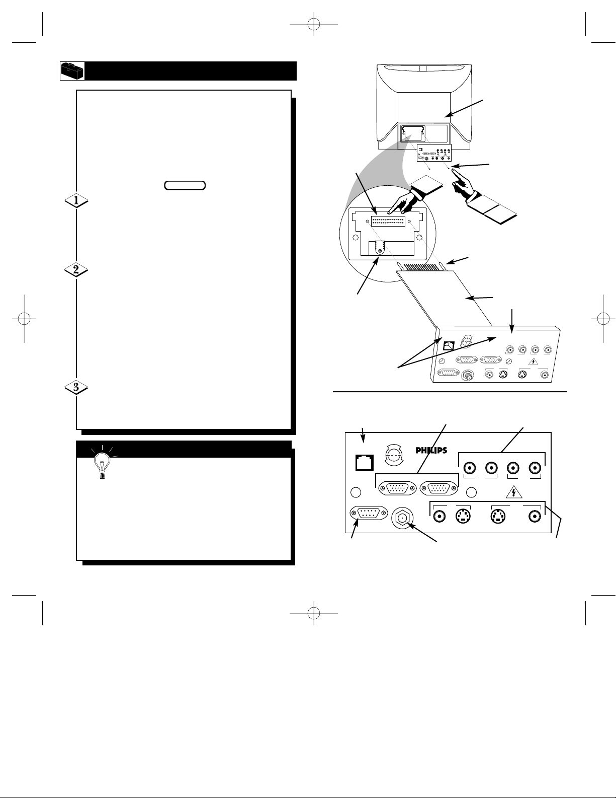
Clone Port - 6 Pin
Connector for limited
applications.
VGA Inputs and Outputs
(Loop Thru)
AUDIO/VIDEO Inputs
and Outputs
(Loop Thru)
VGA/S-VIDEO/S-AUDIO Inputs
and Outputs (Loop Thru) (S-AUDIO
In/Outputs are Audio jacks used
only with the S-VIDEO In/Outputs)
RF IN -
Antenna/Cable
75Ω Input
RS 232 SmartLink™ Connector
for interface between the TV and
a computer (PC or MAC).
I
NSTALLINGSCANCARD
II
8
I
nstallation of the ScanCard II is easy.
Remember to follow these instructions, be
patient, and use the T374AH Set Up Remote
Control (see T374AH Remote Control
Instructions - part # IB7166E002 for complete
details). Note: This is not the remote supplied
with the ScanCard II package.
Start by unplugging the AC power cord
from the wall socket. Remove the hex head
screws holding the card cover in place. Slide the
card cover off. Be careful when pulling the
Antenna jack (RF IN) out of its plug.
Insert the ScanCard II (with its components
facing down) into the back of the TV. Line up
and guide the 32 pin connector into place. Note:
There are guide pins to help line up the Card
properly. Gently, but firmly, press the card into
place by pushing on the card cover directly in line
with the circuit board itself.
DO NOT press the card into place by pushing on
the corners of the card cover.
Press the RF IN (Antenna) jack firmly into
its plug and replace the hex head screws to secure
the card and card cover to the rear of the TV.
Remember, unplug the TV to avoid electrical
shock damage to the TV.
Be sure to align the 32 pin connector before pressing into
place. Never force the ScanCard II into the connector. If it
will not go in smoothly, realign the guide pins and try
again.
Do not use the ScanCard II jacks to push the card
assembly into place. Push on the cover directly behind
the card itself.
SMART HELP
SCAN 2 10/3/00 10:49 AM Page 8
SMART
PLUG
VIDEO
VIDEO
AUDIO
AUDIO
VGA IN VGA OUT
IN OUT
RF IN
OUTIN
RS 232
S-VIDEO
S-VIDEOS-AUDIO S-AUDIO
BEGIN
CLONE
PORT
E
N
RS 232
2
Side Down
U
C
S
O
F
ScanCard II
D
E
H
C
A
N
VGA IN VGA OUT
RF IN
VGA/S-AUDIO
1
3
Component
U
C
S
O
CLONE
F
PORT
RS 232
PHILIPS
E
D
ScanCard II
N
E
H
C
A
N
VGA IN
VGA OUT
RF IN
VIDEO
S-VIDEO
IN
VGA/S-AUDIO
S-VIDEO
AUDIO
IN OUT
S-VIDEO
VIDEO
AUDIO
IN OUT
S-VIDEO
VIDEO
OUTIN
VIDEO
OUT
AUDIO
S-AUDIO
AUDIO
S-AUDIO

11
300 to 75Ω
Adapter
(483521827003)
Combination VHF/UHF
Antenna
(Outdoor or Indoor)
Twin Lead
Wire
Round Cable
75Ω
Back of TV
ScanCard II
Jack Panel
Round Cable 75Ω
75-300 Ohm Adapter
UHF/VHF Combiner
ScanCard II
Jack Panel
Back of TV
Outdoor UHF Antenna
(Twin Lead 300 Ohm)
Outdoor VHF
Antenna
(Twin Lead
300 Ohm)
Outdoor VHF
Antenna
(Round 75Ω
Cable)
Twin Lead
Wire
Round End
OPTIONAL HOOKUPS
10
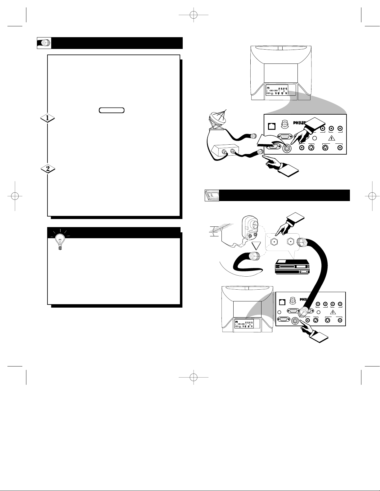
A
combination antenna receives normal
broadcast channels (VHF 2-13 and UHF
14-69). Your connection is easy since there is
only one 75Ω (ohm) antenna plug on the
back of your TV - and that’s where the
antenna goes. (If you have more than one
antenna, please refer to the diagram at the
bottom of page 11 for additional hookups.)
If your antenna has a round cable (75 ohm)
on the end, then you're ready to connect it to the
TV.
If your antenna has flat twin-lead wire (300
ohm), you first need to attach the antenna wires to
the screws on a 300 to 75 ohm adapter.
Push the round end of the adapter (or anten-
na) onto the RF IN plug on the rear of the TV. If
the round end of the antenna wire is threaded,
screw it down tight.
BEGIN
Remember, be sure to set the TV for the
type signal you've connected.
To set the TV to select only the channel numbers
in your area see how to “Program" or "Add" channels in memory.
To order any optional accessory contact your dealer or call the toll-free accessory ordering number
(1-800-292-6066):
• UHF/VHF Combiner: (SBV1133AO1)
• 75-300 Ohm Adapter: (SBV1113AO1)
• 300-75 Ohm Adapter: (483521827003)
SMART HELP
ANTENNA HOOKUPS
SCAN 2 10/3/00 10:49 AM Page 10
1
SMARTSMART
PLUGPLUG
RS 232RS 232
CLONE
PORT
VGA INVGA IN VGA OUTVGA OUT
RS 232
RF INRF IN
VIDEOVIDEO
AUDIOAUDIO
VIDEOVIDEO
AUDIOAUDIO
ININ OUTOUT
OUTOUTININ
S-VIDEOS-VIDEOS-AUDIOS-AUDIO S-AUDIOS-AUDIO
S-VIDEOS-VIDEO
U
C
S
O
F
E
D
N
E
H
C
A
N
VGA IN VGA OUT
RF IN
ScanCard II
S-VIDEO
VIDEO
2
VIDEO
AUDIO
IN OUT
OUTIN
S-VIDEOVGA/S-AUDIO S-AUDIO
AUDIO
SMARTSMART
PLUGPLUG
VIDEOVIDEO
AUDIOAUDIO
VIDEOVIDEO
AUDIOAUDIO
SMART
VGA INVGA IN VGA OUTVGA OUT
ININ OUTOUT
O
F
PLUG
RF INRF IN
OUTOUTININ
RS 232RS 232
S-VIDEOS-VIDEOS-AUDIOS-AUDIO S-AUDIOS-AUDIO
S-VIDEOS-VIDEO
E
N
RS 232
H
VGA IN VGA OUT
UHF
300Ω
VHFV
VHF
OR
75-300 Ω ADAPTER
U
C
S
E
C
A
N
RF IN
D
ScanCard II
VIDEO
S-VIDEO
VIDEO
AUDIO
IN OUT
OUTIN
S-VIDEOS-AUDIO S-AUDIO
AUDIO
13
OPTIONAL VCR HOOKUP
Round Cable
75Ω Supplied
with VCR
VCR
Outdoor VHF/UHF
Antenna
300 to 75Ω Ohm
Adapter
Cable TV signal
Back of TV
ScanCard II
Jack Panel
Back of TV
Round Cable
75Ω Ohm
Cable TV Converter Box
Connection
Cable TV Company
ScanCard II
Jack Panel
12
Y
our Cable TV input into your home may
be a single (75 ohm) cable, or a
Converter Box installation. In either case the
connection to the TV is very easy. Just put
the threaded end of the cable signal to the
TV's antenna plug and screw it down tight.
If your Cable TV signal is a single round
cable (75 ohm) then you're ready to connect to
the TV.
If you have a Cable TV Converter Box:
Connect the Cable TV signal to the Cable Signal
IN(put) plug on the Converter.
Connect the Cable TV cable to the RF IN
plug on the TV.
If you have a Cable TV Converter Box:
Connect the OUT(put) plug from the Converter to
the RF IN plug on the TV (connecting cable supplied with the Converter.)
BEGIN
Remember, set the TV to the “Cable TV
Mode.” Then, to select only the channel
numbers on your Cable system see “Auto
Program" (refer to page 33 for both features).
If you use a Cable Converter box, set the TV to
the same channel as the converter's CH 3/4 switch
(on the rear of the converter.)
SMART HELP
CABLE TV HOOKUP
SCAN 2 10/3/00 10:49 AM Page 12
SMARTSMART
PLUGPLUG
VIDEOVIDEO
VIDEOVIDEO
AUDIOAUDIO
AUDIOAUDIO
VGA INVGA IN VGA OUTVGA OUT
ININ OUTOUT
RF INRF IN
OUTOUTININ
RS 232RS 232
S-VIDEOS-VIDEO
S-VIDEOS-VIDEOS-AUDIOS-AUDIO S-AUDIOS-AUDIO
CLONE
U
C
S
O
F
PORT
E
D
N
E
H
C
A
N
VGA IN VGA OUT
RF IN
OUT
IN
RS 232
ScanCard II
S-VIDEO
VIDEO
2
VIDEO
AUDIO
IN OUT
OUTIN
S-VIDEOVGA/S-AUDIO S-AUDIO
AUDIO
OR
SMARTSMART
PLUGPLUG
VIDEOVIDEO
AUDIOAUDIO
VGA INVGA IN VGA OUTVGA OUT
RF INRF IN
RS 232RS 232
VIDEOVIDEO
ININ OUTOUT
OUTOUTININ
S-VIDEOS-VIDEO
S-VIDEOS-VIDEOS-AUDIOS-AUDIO S-AUDIOS-AUDIO
IN FROM ANT.
AUDIOAUDIO
CLONE
PORT
RS 232
1
1
OUT TO TV
U
C
S
O
F
E
N
E
H
C
A
N
VGA IN VGA OUT
RF IN
D
ScanCard II
VIDEO
S-VIDEO
2
VIDEO
AUDIO
IN OUT
OUTIN
S-VIDEOVGA/S-AUDIO S-AUDIO
AUDIO
 Loading...