

Philips VR120/02, VR120/55, VR120/58, VR170/02, VR170/07 Service Manual
...
Published by LE/MS0110, Videq Service Department Printed in Netherlands Subject to modification 5 3103 785 21760
©
Copyright 2001 Phil ips Consumer Electroni cs B.V. Eindhoven, The Netherlands.
All r ights reser ved. No part of t his publication may be reproduced, stored in a
retri eval system or transmitted, in any form or by any means, elect ronic, mechanical ,
photocopyi ng, or otherwi se without the prior permission of Philips.
Video Cassette Recorder Deck: Turbo Drive APOLLO 13
VR120
/02/55/58
VR170/02/07/39/58
VR220/02/07/39/58
VR270B/02/07/39/58
VR270W/02/07/39/58
VR402/58
VR420/02/39/58
VR520/02/07/16/58
VR570/02/07/16/39/58
VR572/02/16
VR620/02/07/16/39/58
VR622/02/16
VR627/02/16
VR670B/02/07/16
VR670B/39/58
VR670W/02/07/16
VR670W/39/58
VR720/02/07/16/39/58
VR870CC/02/07/16
VR870CC/39/58
VR870L/02/07/16
VR870L/39/58
SB140/03/38
SB145/03/11
SB445/11/38
SB645/03/11/38
SB745/03/11/38
20DV30/39
45DV30/39
65DV30/39
AA
Contents Page
1 List of PWBs, Features, Technical specifications 3
2 Safety instructions, Modifications 10
3 Directions for use 12
4 Dismantling instructions 46
5 Service modes, Repair tips 49
6 Block diagrams, Waveforms, Wiring diagram 57
7 Circuit diagrams and PWB layouts 64
8 Electrical alignments 91
9 Circuit descriptions and List of abbreviations 97
10 Tape deck 113
11 Exploded views 124
12 Spare parts list 128
Survey of versions:
Survey of remote controls:
/02/03 PAL B/G, VPS/PDC
/05 PAL I, UK
/07 PAL I, Ireland
/11 PAL B/G, Belgium
/13 PAL B/G, Nordic
/16 PAL B/G, Spain / Nordic
/38/39 SECAM L, L’ & PAL B/G, I
/55 PAL B/G, I, PAL/SECAM D/K
/58/59 PAL/SECAM B/G, D/K
/60 PAL/SECAM D/K
VR220/02/07/39/58
VR420/02/39/58
RT112/111 8622 661 12111
VR870L/02/07/16/39/58
VR870CC/02/07/16/39/58
RT114/111 8622 661 14111
SB140/03
SB145/03/11
SB445/11
SB645/03/11
SB745/03/11
RT116/201 8622 661 16201
SB140/38
SB445/38
SB645/38
SB745/38
65DV30/39
45DV30/39
20DV30/39
RT116/204 8622 661 16204
VR120/02/16/55/58
VR402/58
VR520/02/07/16/58
RT121/101 8622 661 21101
VR170/07/39/58
VR270W/02/07/39/58
VR570/02/07/16/39/58
VR572/02/16
VR670W/02/07/16/39/58
RT121/111 8622 661 21111
VR270B/02/07/39/58
VR670B/02/07/16/39/58
RT121/121 8622 661 21121
VR620/02/07/16/39/58
VR622/02/16
RT123/111 8622 661 23111
VR627/02/16
VR720/02/07/16/39/58
RT128/112 8622 661 28112

GB 2 VR120
Contents Page Contents Page
1 List of PWBs, Features, Technical
specifications 3
Survey of sets and PWB’s with software versions 3
Features 5
Technical specification 9
2
Safety instructions, Modifications 10
Safety instructions 10
Modifications 11
3 Direction for use 12
Remote control overview 12
Front overview of the sets 14
Direction for use introduction 16
Remote control codes 45
4
Dismantling instructions 46
Dismantling instructions 46
Dismantling of the motherboard/drive
combination 47
Dismantling the drive 48
5 Service modes, Repair tips 49
Special functions 49
Service test program 49
Repair tips 53
6 Block diagrams, Waveforms, Wiring diagram 57
Block diagram Video 57
Block diagram Audio Mono 58
Block diagram Audio Stereo 59
Supply voltages and Bus diagram 60
Supply voltages and Bus diagram 61
Block diagram Central Control 62
Waveforms 63
7 Circuit diagrams and PWB layouts 64
Power supply (PS)64
Display control (AIO2)65
Central control (AIO1)66
Deck control (DE)67
Variant List Frontend (FV)68
Frontend (FV)69
FM stereo (FM-ST)70
FM Stereo + Nicam (FM-ST-NIC)71
Audio Linear (AL) 72
FM - Audio (AF)73
Video Signal Processing - SECAM (VS-SEC)74
Video Signal Processing (VS)75
VPS/PDC & OSD Part (VPO)76
In/Out Part (IO)77
FOLLOW ME Part (FOME)78
Wiring Diagram 79
Mother board - solder side 80
Mother board - component side 83
Connector print (ACP10)84
Connector print (ACP1)84
Connector print (QBOE1)85
Connector print (QBOG1)85
Connector print (ACP35)86
Key print (AKP35)87
Illumination print (AKP13)88
Key print (AKP36) 89
Shuttle board (ASP10)89
Shuttle board (QKP21)89
Test point overview 90
8 Electrical alignments 91
Measuring instruments 91
Setting instructions 91
Video signal processing (VS-SEC)91
Front End (FV)92
Deck electronics (DE)93
Servo System (AIO1)93
Audio Linear (AL)94
Display Control (AIO2)94
9 Circuit descriptions and List of
abbreviations 97
Switched-mode power supply PS (PS Part) 97
Operating unit (DC part) 98
Central Control (AIO part) 99
Deck electronics (DE part) 100
Front end (FV part) 101
Video signal processing VS (VS part) 102
Audio linear (AL part) 104
Audio HiFi - for stereo units (AF part) 105
IN/OUT (IO part) 105
Follow Me (FOME part) 106
VPS/PDC, on-screen display (VPO part) 106
Simple Blockdiagram 107
Simple Blockdiagram FM Audio / Linear Audio
processing 109
List of abbreviations 110
10 Tape deck 113
Drive assembly 113
Adjustments 117
Deck exploded view (TOP) 120
Deck exploded view (BOTTOM) 121
Mechanical parts list 122
11 Exploded views 124
Exploded view set 124
12 Spare parts list 128
List of PWBs, Features, Technical specifications
GB 3VR120 1.
1. List of PWBs, Features, Technical specifications
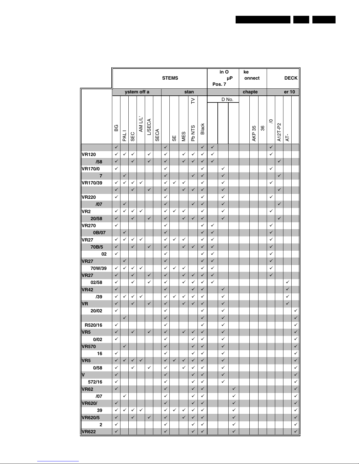
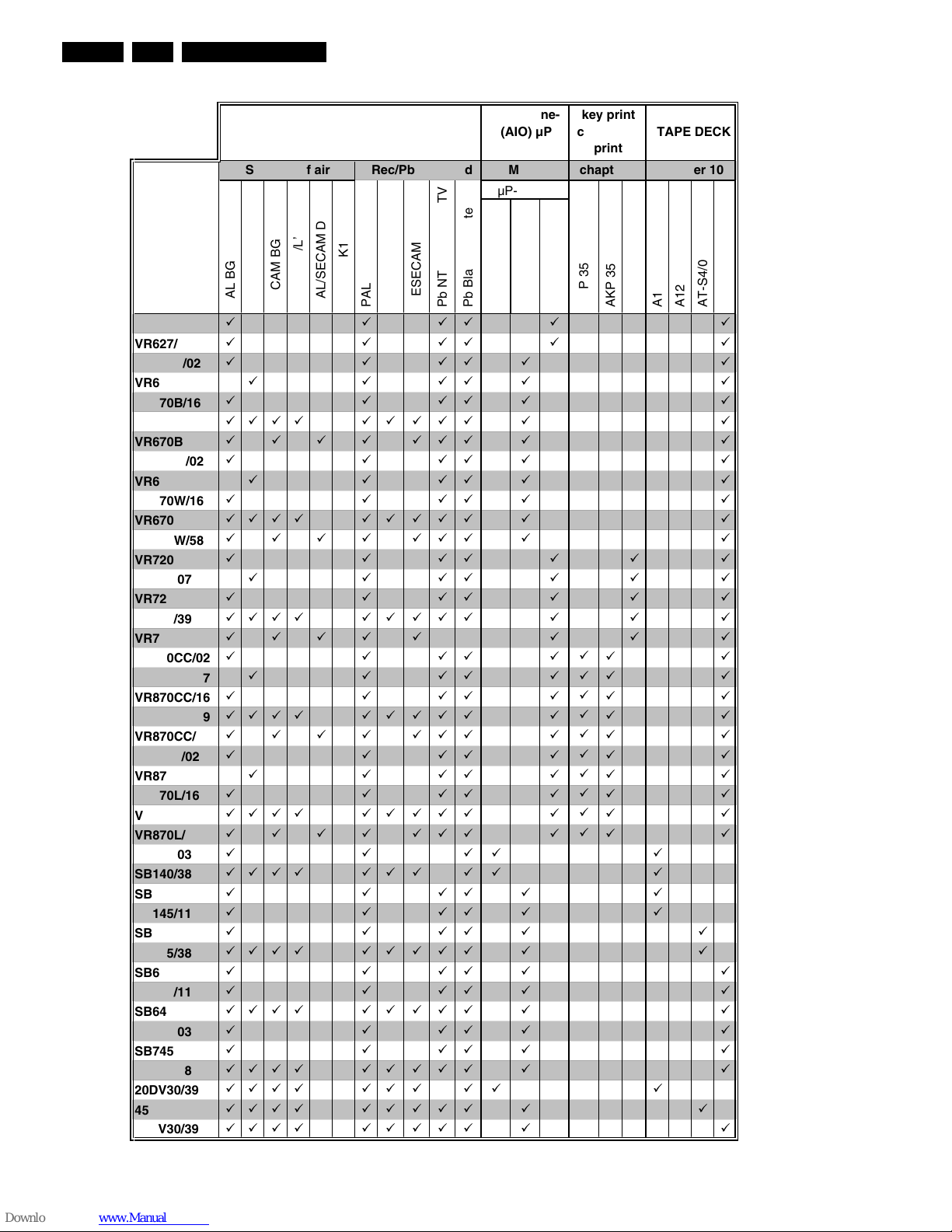
1.1 Survey of sets and PWB’s with software versions
31
32 37
AC3P1 - xU
AC3B1 - xU
AC3P7 - xU
VR120/02
áááá á
VR120/55
ááááá áááá á
VR120/58
áááá áááá á
VR170/02
ááááá
VR170/07
ááááá á
VR170/39
áááá á á á á á á
VR170/58
áááá ááá á á
VR220/02
ááááá
VR220/07
ááááá á
VR220/39
áááá á á á á á á
VR220/58
áááá ááá á á
VR270B/02
áááá á
VR270B/07
áááá á
VR270B/39
áááá á á á á á á
VR270B/58
áááá áááá á
VR270W/02
áááá á
VR270W/07
áááá á
VR270W/39
áááá á á á á á á
VR270W/58
áááá áááá á
VR402/58
áááá áááá á
VR420/02
ááááá á
VR420/39
áááá ááááá á á
VR420/58
áááá ááá á á
VR520/02
áááá á
VR520/07
áááá á
VR520/16
áááá á
VR520/58
áááá ááá á á
VR570/02
ááááá á
VR570/07
ááááá á
VR570/16
ááááá á
VR570/39
áááá ááááá á á
VR570/58
áááá ááá á á
VR572/02
ááááá á
VR572/16
ááááá á
VR620/02
ááááá á
VR620/07
ááááá á
VR620/16
ááááá á
VR620/39
áááá ááááá á á
VR620/58
áááá ááá á á
VR622/02
ááááá á
VR622/16
ááááá á
MoboSystem off air
TAPE DECK SYSTEMS
Rec/Pb standard
All in One-
(AIO) µP
Pos. 7899
chapter 10
AT-S4/2
AKP 35
A12T-P2/0
AT-S4/0
AKP 36
A12T-P2/0LP
µP-ID No.
MESECAM
Pb Black & White
Pb NTSC on PAL TV
SECAM
PAL BG
SECAM BG
PAL/SECAM DK
PAL
PAL I
SECAM K1
SECAM L/L’
key print
connector
print
chapter 7
ACP 35
List of PWBs, Features, Technical specifications
GB 4 VR1201.
31
32 37
AC3P1 - xU
AC3B1 - xU
AC3P7 - xU
VR627/02
ááááá á
VR627/16
ááááá á
VR670B/02
ááááá á
VR670B/07
ááááá á
VR670B/16
ááááá á
VR670B/39
áááá ááááá á á
VR670B/58
áááá ááá á á
VR670W/02
ááááá á
VR670W/07
ááááá á
VR670W/16
ááááá á
VR670W/39
áááá ááááá á á
VR670W/58
áááá ááá á á
VR720/02
ááááááá
VR720/07
ááááááá
VR720/16
ááááááá
VR720/39
áááá ááááá á á á
VR720/58
áááá á á á á
VR870CC/02
ááááááá
VR870CC/07
ááááááá
VR870CC/16
ááááááá
VR870CC/39
áááá ááááá á á á
VR870CC/58
áááá ááá á á á
VR870L/02
ááááááá
VR870L/07
ááááááá
VR870L/16
ááááááá
VR870L/39
áááá ááááá á á á
VR870L/58
áááá ááá á á á
SB140/03
áááá á
SB140/38
áááá á á á á á á
SB145/03
áááááá
SB145/11
áááááá
SB445/11
ááááá á
SB445/38
áááá ááááá á á
SB645/03
ááááá á
SB645/11
ááááá á
SB645/38
áááá ááááá á á
SB745/03
ááááá á
SB745/11
ááááá á
SB745/38
áááá ááááá á á
20DV30/39
áááá á á á á á á
45DV30/39
áááá ááááá á á
65DV30/39
áááá ááááá á á
A12T-P2/0LP
AT-S4/0
AT-S4/2
AKP 35
AKP 36
ACP 35
A12T-P2/0
MESECAM
Pb NTSC on PAL TV
Pb Black & White
µP-ID No.
PAL/SECAM DK
SECAM K1
PAL
SECAM
PAL BG
PAL I
SECAM BG
SECAM L/L’
Rec/Pb standard chapter 7
SYSTEMS TAPE DECK
System off air Mobo chapter 10
All in One-
(AIO) µP
Pos. 7899
key print
connector
print
á
á
á
á
á
á
á
á
á
á
List of PWBs, Features, Technical specifications
GB 5VR120 1.
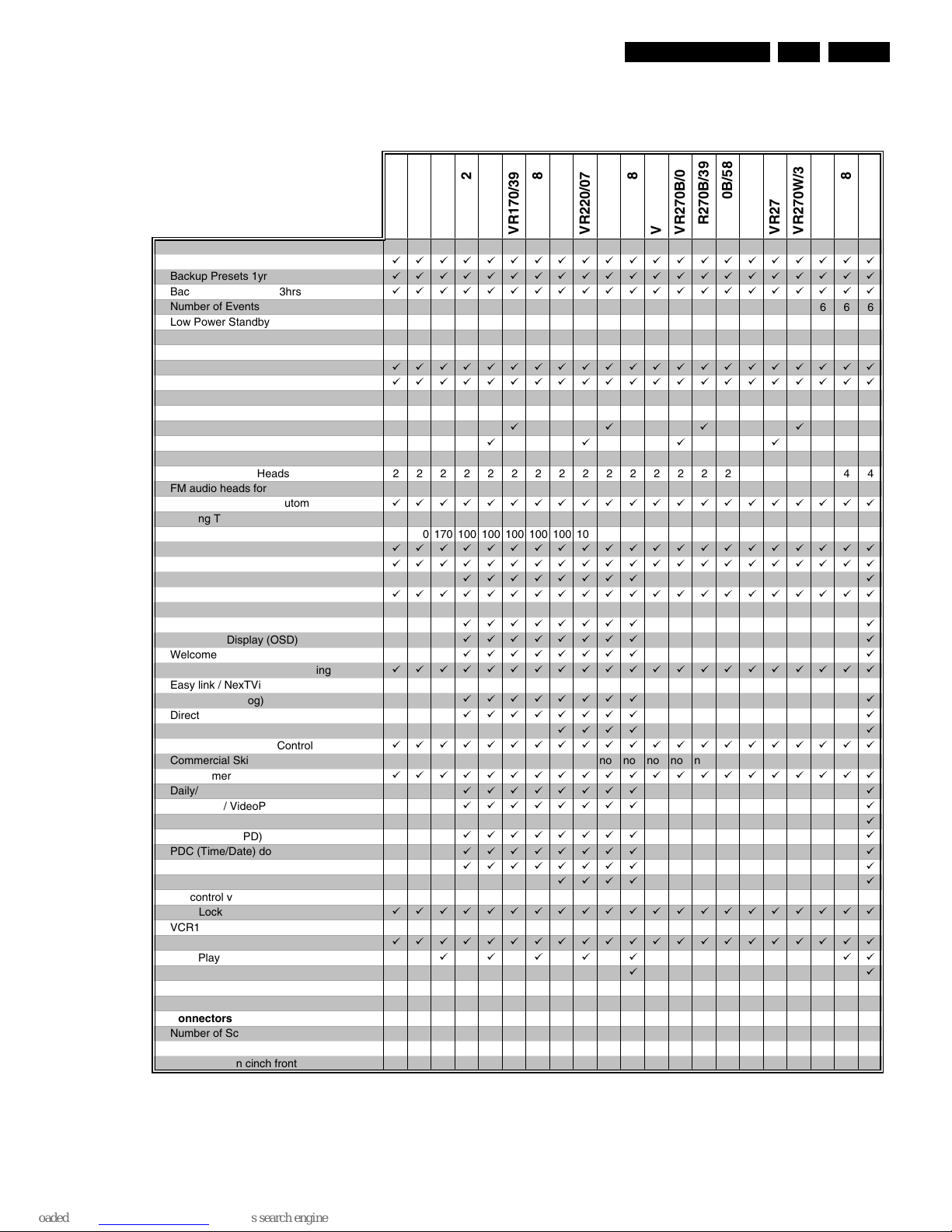
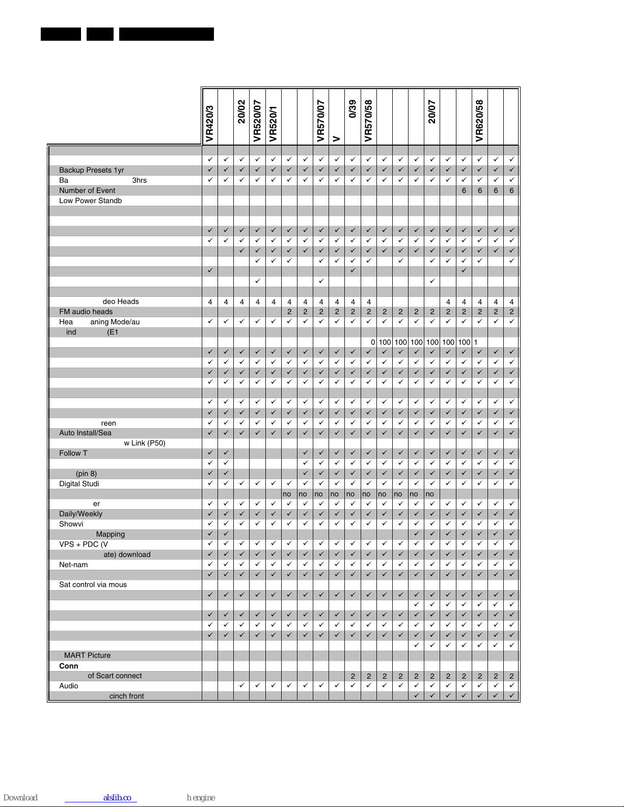
1.2 Features
General
Auto Standby On/Off
ббббббббббббббббббббб
Backup Presets 1yr
ббббббббббббббббббббб
Backup Clock / Timer 3hrs
ббббббббббббббббббббб
Number of Events / month
666666666666666666666
Low Power Standby Power Cons. [Watts] <4 <4 <4 <4 <4 <4 <4 <4 <4 <4 <4 <4 <4 <4 <4 <4 <4 <4 <4 <4 <4
Tuning - presets (only channel input)
99 99 99 99 99 99 99 99 99 99 99 99 99 99 99 99 99 99 99 99 99
Systems
Hyperband, UHF, VHF
ббббббббббббббббббббб
Mono
ббббббббббббббббббббб
German Stereo
NICAM
Splitter
áááá
Auto Seek
áááá
Mechanism
Number of Video Heads
222222222222222222244
FM audio heads for stereo
Head Cleaning Mode/automatic
ббббббббббббббббббббб
Winding Time (E180) sec
260 260 260 100 100 100 100 100 100 100 100 260 260 260 260 260 260 260 260 260 100
Rewind Time (E180) sec
170 170 170 100 100 100 100 100 100 100 100 170 170 170 170 170 170 170 170 170 100
Quick View
ббббббббббббббббббббб
Tape Counter lin. Relative (h.m.s.)
ббббббббббббббббббббб
Tape Counter Time Left (h.m)
бббббббб á
VISS: next/prev. index / blank tape search
ббббббббббббббббббббб
Features
Plug & Play
бббббббб á
On Screen Display (OSD)
бббббббб á
Welcome Screen
бббббббб á
Auto Install/Search/Store/Tuning
ббббббббббббббббббббб
Easy link / NexTView Link (P50)
Follow TV (analog)
бббббббб á
Direct Record
бббббббб á
16:9 (pin 8)
áááá á
Digital Studio Picture Control
ббббббббббббббббббббб
Commercial Skip no no no no no no no no no no no no no no no no no no no no no
Turbo Timer
ббббббббббббббббббббб
Daily/Weekly
бббббббб á
Showview / VideoPlus+
бббббббб á
ShowView Mapping
á
VPS + PDC (VPD)
бббббббб á
PDC (Time/Date) download
бббббббб á
Net-name detection
бббббббб á
Record Link / Scart 2
áááá á
Sat control via Mouse
Child Lock
ббббббббббббббббббббб
VCR1/VCR2
OTR
ббббббббббббббббббббб
Long Play
ббббб áá
Auto LP
áá
Tape List
SMART Picture
Connectors
Number of Scart connectors
111222222221121112112
Audio out cinch rear
Audio/Video in cinch front
VR220/07
VR220/39
VR270B/58
VR270W/07
VR270W/58
VR402/58
VR270W/39
VR170/07
VR170/58
VR220/02
VR220/58
VR270B/07
VR120/02
VR120/55
VR170/02
VR170/39
VR120/58
VR270W/02
VR270B/39
VR270B/02
VR420/02
List of PWBs, Features, Technical specifications
GB 6 VR1201.
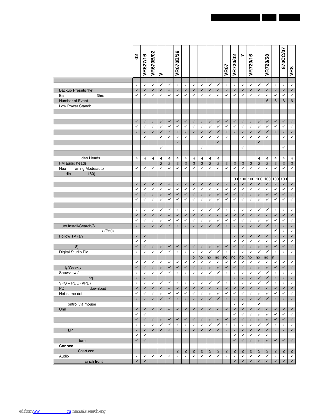
General
Auto Standby On/Off
бббббббббббббббббббб
Backup Presets 1yr
бббббббббббббббббббб
Backup Clock / Timer 3hrs
бббббббббббббббббббб
Number of Events / month
66666666666666666666
Low Power Standby Power Cons. [Watts] <4 <4 <4 <4 <4 <4 <4 <4 <4 <4 <4 <4 <4 <4 <4 <4 <4 <4 <4 <4
Tuning - presets (only channel input)
99 99 99 99 99 99 99 99 99 99 99 99 99 99 99 99 99 99 99 99
Systems
Hyperband, VHF, UHF
бббббббббббббббббббб
Mono
бббббббббббббббббббб
German Stereo
бббббббббббббббббб
NICAM
ááá áááá á áááá á
Splitter
ááá
Auto Seek
áá á
Mechanism
Number of Video Heads
44444444444444444444
FM audio heads for stereo
222222222222222222
Head Cleaning Mode/automatic
бббббббббббббббббббб
Winding Time (E180) sec
100 100 100 100 100 100 100 100 100 100 100 100 100 100 100 100 100 100 100 100
Rewind Time (E180) sec
100 100 100 100 100 100 100 100 100 100 100 100 100 100 100 100 100 100 100 100
Quick View
бббббббббббббббббббб
Tape Counter lin. Relative (h.m.s.)
бббббббббббббббббббб
Tape Counter Time Left (h.m)
бббббббббббббббббббб
VISS: next/prev. index / blank tape search
бббббббббббббббббббб
Features
Plug & Play
бббббббббббббббббббб
On Screen Display (OSD)
бббббббббббббббббббб
Welcome Screen
бббббббббббббббббббб
Auto Install/Search/Store/Tuning
бббббббббббббббббббб
Easy link / NexTView Link (P50)
Follow TV (analog)
áá бббббббббббббб
Direct Record
áá бббббббббббббб
16:9 (pin 8)
áá бббббббббббббб
Digital Studio Picture Control
бббббббббббббббббббб
Commercial Skip no no no no no no no no no no no no no no no no no no no no
Turbo Timer
бббббббббббббббббббб
Daily/Weekly
бббббббббббббббббббб
Showview / VideoPlus+
бббббббббббббббббббб
ShowView Mapping
áá ббббббб
VPS + PDC (VPD)
бббббббббббббббббббб
PDC (Time/Date) download
бббббббббббббббббббб
Net-name detection
бббббббббббббббббббб
Record Link / Scart 2
бббббббббббббббббббб
Sat control via mouse
Child Lock
бббббббббббббббббббб
VCR1/VCR2
ббббббб
OTR
бббббббббббббббббббб
Long Play
бббббббббббббббббббб
Auto LP
бббббббббббббббббббб
Tape List
ббббббб
SMART Picture
Connectors
Number of Scart connectors
22222222222222222222
Audio out cinch rear
бббббббббббббббббб
Audio/Video in cinch front
ббббббб
VR570/07
VR570/16
VR622/16
VR622/02
VR572/16
VR572/02
VR620/16
VR620/39
VR620/02
VR620/07
VR520/07
VR420/39
VR420/58
VR520/02
VR620/58
VR520/16
VR520/58
VR570/02
VR570/39
VR570/58
List of PWBs, Features, Technical specifications
GB 7VR120 1.
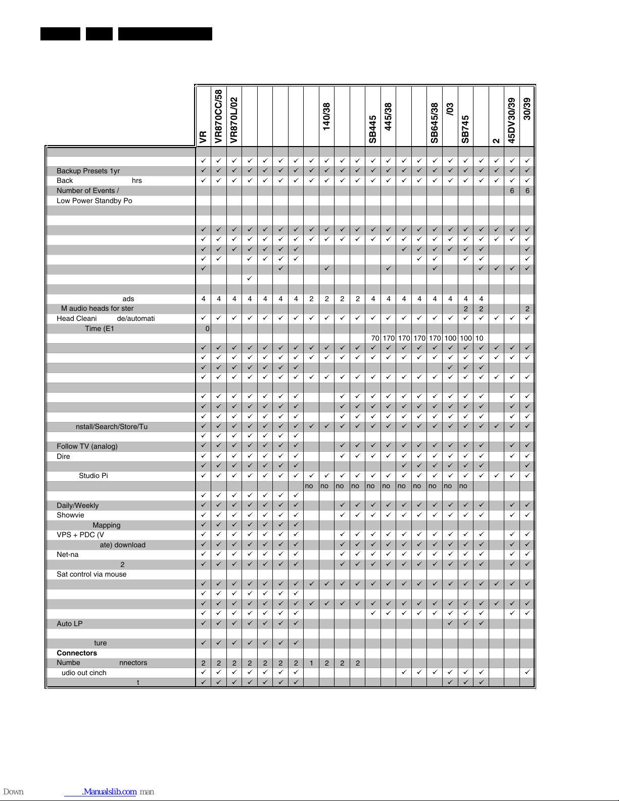
General
Auto Standby On/Off
бббббббббббббббббббб
Backup Presets 1yr
бббббббббббббббббббб
Backup Clock / Timer 3hrs
бббббббббббббббббббб
Number of Events / month
66666666666666666666
Low Power Standby Power Cons. [Watts] <4 <4 <4 <4 <4 <4 <4 <4 <4 <4 <4 <4 <4 <4 <4 <4 <4 <4 <4 <4
Tuning - presets (only channel input)
99 99 99 99 99 99 99 99 99 99 99 99 99 99 99 99 99 99 99 99
Systems
Hyperband, UHF, VHF
бббббббббббббббббббб
Mono
бббббббббббббббббббб
German Stereo
бббббббббббббббббббб
NICAM
á áááá áááá áááá áá
Splitter
ááá
Auto Seek
áááá
Mechanism
Number of Video Heads
44444444444444444444
FM audio heads for stereo
22222222222222222222
Head Cleaning Mode/automatic
бббббббббббббббббббб
Winding Time (E180) sec 100 100 100 100 100 100 100 100 100 100 100 100 100 100 100 100 100 100 100 100
Rewind Time (E180) sec 100 100 100 100 100 100 100 100 100 100 100 100 100 100 100 100 100 100 100 100
Quick View
бббббббббббббббббббб
Tape Counter lin. Relative (h.m.s.)
бббббббббббббббббббб
Tape Counter Time Left (h.m)
бббббббббббббббббббб
VISS: next/prev. index / blank tape search
бббббббббббббббббббб
Features
Plug & Play
бббббббббббббббббббб
On Screen Display (OSD)
бббббббббббббббббббб
Welcome Screen
бббббббббббббббббббб
Auto Install/Search/Store/Tuning
бббббббббббббббббббб
Easy link / NexTView Link (P50)
ááá
Follow TV (analog)
áá бббббббб
Direct Record
áá бббббббб
16:9 (pin 8)
бббббббббббббббббббб
Digital Studio Picture Control
бббббббббббббббббббб
Commercial Skip no no no no no no no no no no no no no no no no no no no no
Turbo Timer
бббббббббббббббббббб
Daily/Weekly
бббббббббббббббббббб
Showview / VideoPlus+
бббббббббббббббббббб
ShowView Mapping
áá бббббббб
VPS + PDC (VPD)
бббббббббббббббббббб
PDC (Time/Date) download
бббббббббббббббббббб
Net-name detection
бббббббббббббббббббб
Record Link / Scart 2
бббббббббббббббббббб
Sat control via mouse
áá á
Child Lock
бббббббббббббббббббб
VCR1/VCR2
áá бббббббб
OTR
бббббббббббббббббббб
Long Play
бббббббббббббббббббб
Auto LP
бббббббббббббббббббб
Tape List
áá ббббб
SMART Picture
áá бббббббб
Connectors
Number of Scart connectors
22222222222222222222
Audio out cinch rear
бббббббббббббббббббб
Audio/Video in cinch front
áá бббббббб
VR670B/39
VR670B/58
VR670B/16
VR670W/02
VR670W/16
VR670W/39
VR670W/07
VR870CC/02
VR870CC/07
VR720/58
VR670W/58
VR720/07
VR720/16
VR720/02
VR870CC/16
VR720/39
VR627/02
VR627/16
VR670B/02
VR670B/07
List of PWBs, Features, Technical specifications
GB 8 VR1201.
General
Auto Standby On/Off
бббббббббббббббббббббб
Backup Presets 1yr
бббббббббббббббббббббб
Backup Clock / Timer 3hrs
бббббббббббббббббббббб
Number of Events / month
6666666666666666666666
Low Power Standby Power Cons. [Watts] <4 <4 <4 <4 <4 <4 <4 <4 <4 <4 <4 <4 <4 <4 <4 <4 <4 <4 <4 <4 <4 <4
Tuning - presets (only channel input)
99 99 99 99 99 99 99 99 99 99 99 99 99 99 99 99 99 99 99 99 99 99
Systems
Hyperband, UHF, VHF
бббббббббббббббббббббб
Mono
бббббббббббббббббббббб
German Stereo
ббббббб бббббб á
NICAM
áá áááá áá áá á
Splitter
á á á á á áááá
Auto Seek
á
Mechanism
Number of Video Heads
4444444222244444444244
FM audio heads for stereo
2222222 222222 2
Head Cleaning Mode/automatic
бббббббббббббббббббббб
Winding Time (E180) sec 100 100 100 100 100 100 100 260 260 260 260 260 260 260 260 260 100 100 100 260 260 260
Rewind Time (E180) sec 100 100 100 100 100 100 100 170 170 170 170 170 170 170 170 170 100 100 100 170 170 170
Quick View
бббббббббббббббббббббб
Tape Counter lin. Relative (h.m.s.)
бббббббббббббббббббббб
Tape Counter Time Left (h.m)
ббббббб ááá
VISS: next/prev. index / blank tape search
бббббббббббббббббббббб
Features
Plug & Play
ббббббб бббббббббб áá
On Screen Display (OSD)
ббббббб бббббббббб áá
Welcome Screen
ббббббб бббббббббб áá
Auto Install/Search/Store/Tuning
бббббббббббббббббббббб
easy link / NexTView Link (P50)
ббббббб
Follow TV (analog)
ббббббб бббббббббб áá
Direct Record
ббббббб бббббббббб áá
16:9 (pin 8)
ббббббб бббббб á
Digital Studio Picture Control
бббббббббббббббббббббб
Commercial Skip no no no no no no no no no no no no no no no no no no no no no no
Turbo Timer
ббббббб
Daily/Weekly
ббббббб бббббббббб áá
Showview / VideoPlus+
ббббббб бббббббббб áá
ShowView Mapping
ббббббб
VPS + PDC (VPD)
ббббббб бббббббббб áá
PDC (Time/Date) download
ббббббб бббббббббб áá
Net-name detection
ббббббб бббббббббб áá
Record Link / Scart 2
ббббббб бббббббббб áá
Sat control via mouse
Child Lock
бббббббббббббббббббббб
VCR1/VCR2
ббббббб
OTR
бббббббббббббббббббббб
Long Play
ббббббб бббббббб áá
Auto LP
ббббббб ááá
Tape List
SMART Picture
ббббббб
Connectors
Number of Scart connectors
2222222122222222222222
Audio out cinch rear
ббббббб бббббб á
Audio/Video in cinch front
ббббббб ááá
VR870CC/58
VR870L/02
VR870CC/39
VR870L/07
VR870L/39
VR870L/58
VR870L/16
SB140/03
SB145/03
SB145/11
SB140/38
20DV30/39
65DV30/39
45DV30/39
SB445/11
SB645/03
SB645/11
SB445/38
SB645/38
SB745/11
SB745/38
SB745/03

List of PWBs, Features, Technical specifications
GB 9VR120 1.
1.3 Technical specification
Mains voltage : 220 - 240 V, +/- 10%
Mains frequency : 45 - 65 Hz
Power consumption : mono 12.5 W during
operation
: HiFi 16 W during
operation
without Low Power Standby : mono 4 W during
standby
: HiFi 4.4 W during
standby
with Low Power Standby : < 4 W standby
Ambient temperature : +10°C to +35°C
Relative humidity : 20 - 80 %
Dimensions : 380 x 260 x 94 mm
Weight : 3,7 kg
Fast forward/rewind time (turbo) : typ. 100s (E180
cass.)
Position of use : horizontally, max.
15°
Video resolution : ≥240 lines
Audio SP: Linear Audio : 80Hz - 10kHz (±6
dB)
Audio LP: Linear Audio : 80Hz - 5kHz (±6
dB)
Stereo FM Audio : 20Hz - 20kHz
(±3dB)
Euroconnector (AV1) SCART plug 1
Connection to TV, monitor, projection TV ...
Pin 1 ARO (audio right out) 500 mV
rms
+/- 3 dB R
out
1kOhm
Pin 2 ARI (audio right in) 0,2 V
rms
to 2V
rms
Rin10 kOhm
Pin 3 ALO (audio left out) 500 mV
rms
+/- 3 dB R
out
1kOhm
Pin 6 ALI (audio left in) 0,2 V
rms
to 2 V
rms
Rin10 kOhm
Pin 7 Blue (out) **)
Pin 8 Switching output: (with R
load
= 10kOhm, C
load
<2nF)
low: 2 V
high: 9.5 V
rise time: 5 ms
Pin 11 Green (out) **)
Pin 15 Red (out) **)
Pin 16 Blanking (out) **) loop through enabled during
standby, view-mode
Pin 19 CVBS II (video out) 1 V
pp
+1/-2dB R
out
75 Ohm
Pin 20 CVBS I (video in) 1 V
pp
+3/-3dB Rin75 Ohm
**) passive loop through from AV2
Euroconnector (AV2) SCART plug 2
Connection to decoder, SAT tuner, video disc, 2nd VCR ...
Pin 1 ARO (audio right out) 500 mV
rms
+/- 3 dB R
out
1kOhm
Pin 2 ARI (audio right in) 0,2 V
rms
to 2V
rms
Rin10 kOhm
Pin 3 ALO (audio left out) 500 mV
rms
+/- 3 dB R
out
1kOhm
Pin 6 ALI (audio left in) 0,2 V
rms
to 2 V
rms
Rin10 kOhm
Pin 7 Blue (out) **)
Pin 8 Switching input only: low: 2 V (low) R
in
10 kOhm
high: 4.5 V (high) R
in
10 kOhm
Pin 11 Green (in) *)
Pin 15 Red (in) *)
Pin 16 Blanking (in) *) loop through enabled during
standby, view-mode
Pin 19 CVBS II (video out) 1 V
pp
+1/-2dB R
out
75 Ohm
Pin 20 CVBS I (video in) 1 V
pp
+3/-3dB Rin75 Ohm
*) passive loop through to Euroconnector AV1
Cinch Audio/Video input on front panel (OPTION)
Audio:
AINFR (audio right in) red 0.2 V
rms
to 2 V
rms
typ. 500 mV
rms
AINFL (audio left in) white 0.2 V
rms
to 2 V
rms
typ. 500 mV
rms
Input impedance 47 kOhm
Video:
VFR yellow 1 Vpp + 3 / -3 dB
Input impedance 75 Ohm
Cinch Audio Out Rear (OPTION)
AOUT1R (audio right out) red 500 mV
rms
+/- 3 dB R
out
1 kOhm
AOUT1L (audio left out) white 500 mV
rms
+/- 3 dB R
out
1 kOhm
This outputs are in parallel with the corresponding outputs on
Euroconnector 1.
TUMOD
Modulator:
Frequency range loop through 45 MHz - 860 MHz
Gain: ANT IN - TV OUT 2 dB + 3 / -2 dB
ANT IN - TUN OUT 2 dB + 3 / -2 dB
Switch for RF input attenuation NO
Frequency range out (tuned by IIC bus) Ch 21 - Ch55
Tuner:
Frequency range 43 MHz - 860 MHz
for UK 450 MHz - 860MHz
Input voltage max. < 100 dBµV
min. > 60 dBµV

Safety instructions, Modifications
GB 10 VR1202.
2. Safety instructions, Modifications
2.1 Safety instructions
• Safety regulations demand that the set be restored to its
original condition and that components identical with the
original types be used.
• Safety components are marked by the symbol h
• All ICs and many other semi-conductors are susceptible
to electrostatic discharges (ESD). Careless handling
during repair may reduce life drastically. When repairing,
make sure that you are conneted with the same potential
as the mass of the set via a wrist wrap with resistance.
Keep components and tools on the same potential.
• A set to be repaired should always be connected to the
mains via a suitable isolating transformer.
• Never replace any modules or any other parts while the
set is switched on.
• Use plastic instead of metal alignment tools. This in order
to prelude short-circuit or to prevent a specific circuit from
being rendered unstable.
2.1.1 Remarks
• The direct voltages and oscillograms ought to be
measured relative to the set mass.
• The direct voltages and oscillograms mentioned in the
diagrams ought to be measured with a colour bar signal
and the picture carrier at 503.25 MHz (C25).
• The oscillograms and direct voltages have been
measured in RECORD or PLAY mode.
• The semiconductors, which are mentioned in the circuit
diagram and in the parts lists, are fully exchangeable per
position with the semiconductors in the set, irrespective
of the type designation of these semiconductors.
Engineer's remarks:
Safety instructions, Modifications
GB 11VR120 2.
2.2 Modifications
2.2.1 Updating the service manual
All modifications and/or supplements to the Service Manual
are published by means of Service Information bulletins.
Each Service Information is numbered:
A Service Information bulletin consists of a front page which,
if needed, is followed by supplementary and/or replacement
sheets.
Replacement sheets should replace existing sheets in the
Service Manual. These sheets are identified by an additional
letter after the page number.
Example: Page 5-1a replaces page 5-1 in the Service
Manual.
Supplementary sheets should be inserted between existing
sheets in the Service Manual. These sheets are identified by
an additional figure after the page number.
Example: Page 5-1-1 should be inserted after page 5-1.
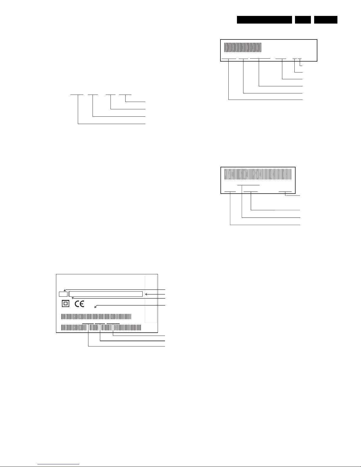
2.2.2 Modifications in the set
All important parts of the set (such as the tape deck, the
printed circuits and modules) are equiped with a sticker.
Those stickers provide a number of important information.
Type plate
The type plate is located on the back cover.
Note:
• In case of an important change in the set, the production
code on the type plate is incremented: E.g. 37 becomes
38.
• In case of a major change in the set, the evolution code
is incremented: E.g. AA becomes AB.
Tape deck
Note:
• The production code and the serial number on the tape
deck do not correspond to the production code and the
serial number on the type plate.
Printed circuits
The sticker is generally located on the copper side of the
board.
Example:
Note:
• The production code number might not always be
mentioned.
In case of an important modification, the last figure of the
factory code number (point number) is increased by one: E.g.
8502.1 becomes 8502.2
VR 01 - 01 GB
Language
Sequence number
Year
220-240 V ~
50Hz
MADE IN EUROPE
MADE IN EUROPE
MODEL NO:
MODEL NO:
PROD.NO:
VR120/02
VN 37 0015 123456
VN 37 123456
SHOWVIEW IS
A TRADEMARK
APPLIED
SHOWVIEW IS
A TRADEMARK
APPLIED
GEMST
AR DEVELOPMENT
CORP
.
GEMST
AR DEVELOPMENT
CORP
.
FOR
BY GEMST
AR
DEVELOPMENT
CORP
.
FOR
BY GEMST
AR
DEVELOPMENT
CORP
.
SHOWVIEW
SYSTEM
IS MANUF
ACTURED
SHOWVIEW
SYSTEM
IS MANUF
ACTURED
UNDER
LICENSE
FROM
UNDER
LICENSE
FROM
Range
Option codes (A-G)
Evolution code
Type number
Serial number
Production date
Production center (VN),
Production code
AA
AAA BBB CCC DDD EEE FFF GGG
A13
12345678 10001 A12T-P2/0LP
011731 12WD44
Production code
Factory indication
Production date
Tape deck type
Factory deck number
AVR 01102
12345 KW 015 123456
Serial number
Production week
Printed boardname
Factor
y
code
Direction for use
GB 12 VR1203.
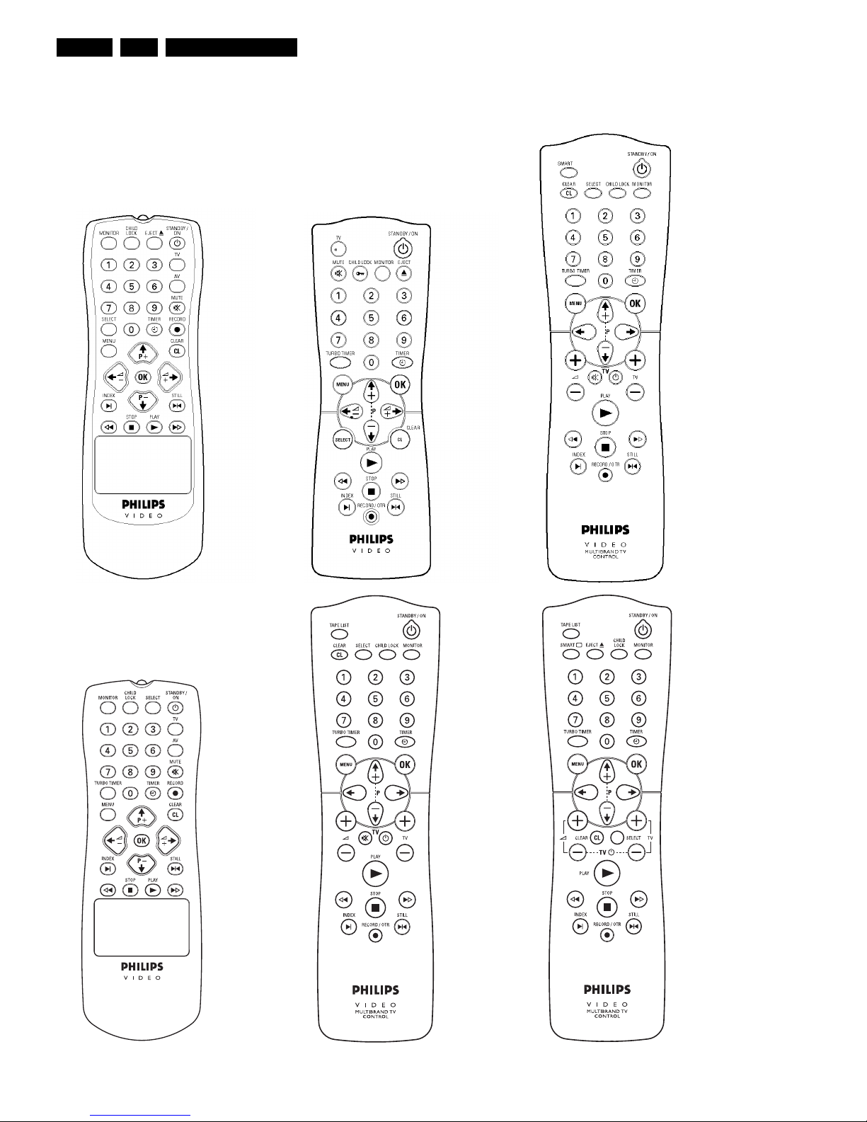
3. Direction for use
RT111
RT116
RT112
RT114
RT123
RT121
RT128

Direction for use
GB 13VR120 3.
SMART
SMART: To adjust the picture setting during playback
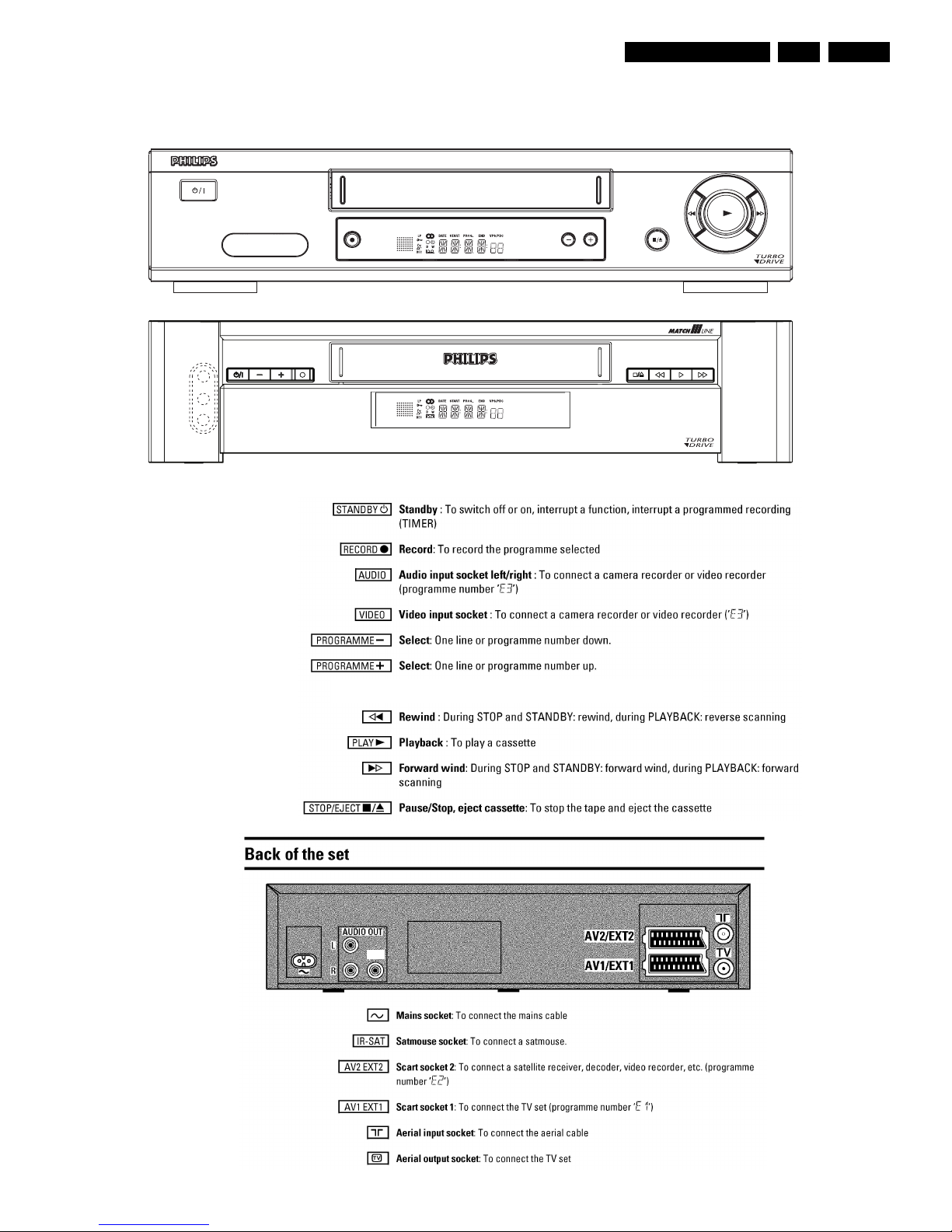
STANDBY/ON m
Switch off : To switch off set, interrupt menufunction, interrupt a programmed recording
(TIMER)
CLEAR (CL)
Delete : To delete last entry/Clear programmed recording (TIMER)
SELECT
Select: To select a function
CHILD LOCK
Child Lock : To switch child lock on/off
MONITOR
TV monitor : To switch between TV reception and VCRplayback
0-9
Number buttons:0-9
TURBO TIMER
TurboTimerAufnahmen programmieren mit der Funktion TurboTimer
TIMER k
TIMER: To make a manual TIMER programming or to alteror clear a programmed TIMER
MENU
Menu : To call up or end main menu
OK
Store/Confirm: To store or confirm entry
Q
Select: Cursor left
P
Select: Cursor right
;Pq
Select: To select a programme number
rP=
Select: To select a programme number
PLAY G
Playback : To play a recorded cassette
H
Rewind : During STOP and STANDBY:rewind, during PLAYBACK: reverse scanning
STOP h
Pause/Stop: To stop the tape, except while a TIMER-recordingis being made
I
Forward wind: During STOP and STANDBY:forward wind, during PLAYBACK: forward
scanning
INDEX E
Index search: In combination with
H/I
: to search for previous or next recording
on the cassette.
RECORD n
Record: To record the programme selected
STILL R
Still picture : To stop the tape and show a stillpicture
Additional TV functions
Sq
TV volume: TV volume up
Sr
TV volume: TV volume down
TV y
TV sound off : To switch the sound on or off
TV m
Switch off : To switch off the TV
TV q
TV Programme number: TV programme number up
TV r
TV Programme number: TV programme number down
Remote control
Direction for use
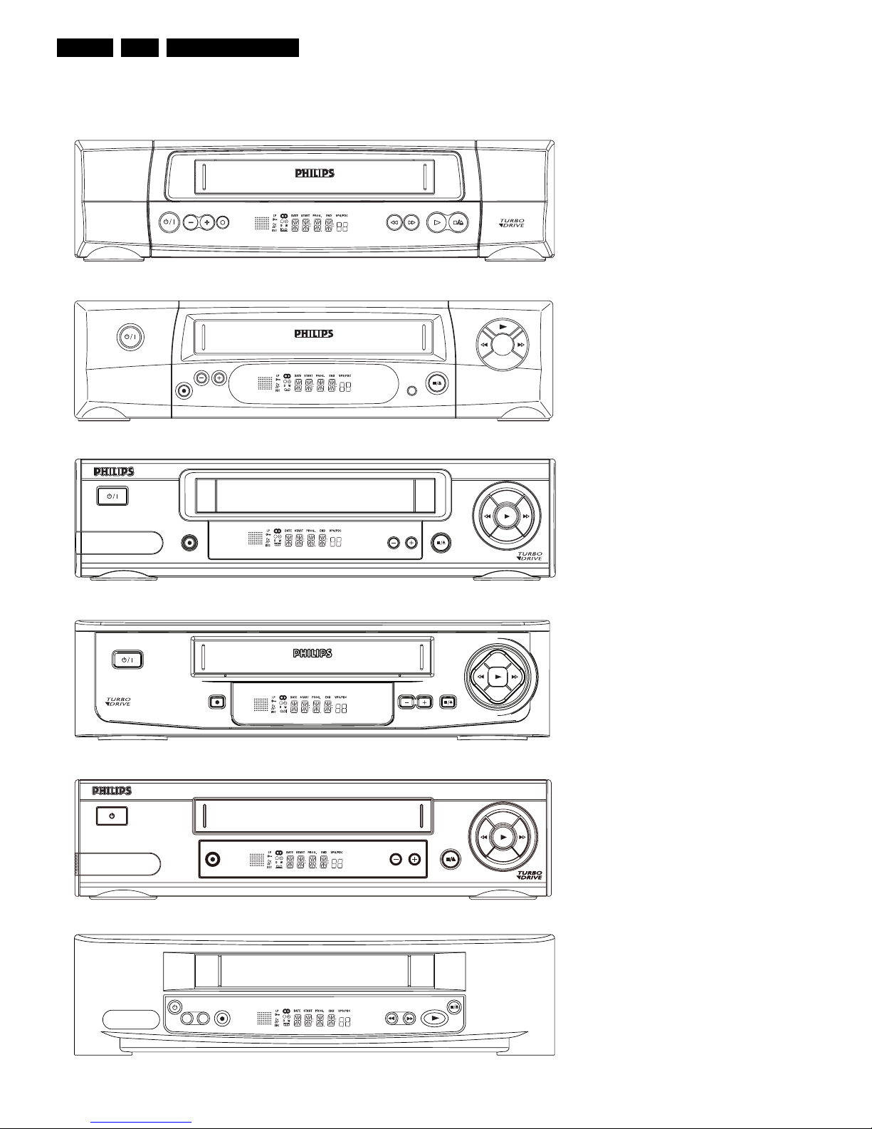
GB 14 VR1203.
-
+
VR120
VR402
VR520
VR170
VR570
VR572
VR220
VR420
VR270B
VR270W
VR670B
VR670W
VR620
VR622
VR627
SB140
SB145
SB445
SB645
SB745
20DV30
45DV30
65DV30
Set width 380 mm
Direction for use
GB 15VR120 3.
SAT
VR870L
VR870C
C
VR720
Set width 435 mm
Direction for use
GB 16 VR1203.
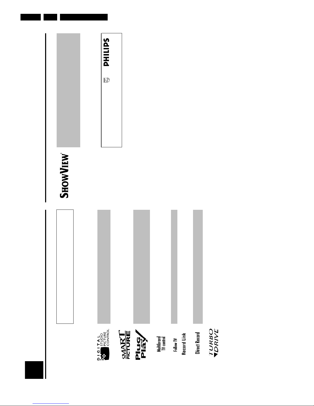
Simple programming system for video recorders. Makes programming as easy as makingatelephone call. Simply enter the number code associated with your television programme.
This
number is located in your favourite television listings magazine.
ShowView is a registered trademark of Gemstar Development Corporation. The ShowV
iew
system is manufactured under licence from Gemstar Development Corporation.
So that you can identify your machine for service questions or in the event of theft, enter
the
serial number here. The serial number (PROD.NO.) is printed on the type plate fixed at
the
back of the device.
MODEL NO. VR720/58
PROD. NO. ..................
Special functions of your new video
recorder
Your PHILIPS video recorder is not just for recording and playing back VHS cassettes. It also
has
a whole range of special functions which will make the day-to-day use of your new v
ideo
recorder much easier.
Philips has developed a system which produces the best possible playback quality. For old
and
often-used video cassettes, this system reduces interference. For new or high quality cassette
s, it
emphasises the details.
This function allows you to save the playback settings that suit you best. Select your own personalsettings for this type of film you are currently watching.
When you connect your video recorder to your television and plug it into the wall socket,
you
will be welcomed with a screen menu. All you have to do is follow the instructions in
the
'intelligent help line' for the next step. Enjoy the automatic TV channel search/save function
and
the automatic time setting.
You can operate the main functions on your television using your video recorder remote control,even if your television is not a Philips.
This function automatically transfers all the television channel settings onto your video record
er.
Recordings made on your video recorder can be controlled by an external satellite receiver.
Your video recorder can ascertain which channel is currently playing on your television
and
record from it at the touch of a button.
The precision tape drive from Philips provides short rewind times and automatic tape length
recognition.
1
Introduction
Direction for use
GB 17VR120 3.
Connecting the video recorder
Preparing the remote control for
operation
The remote control and its batteries are packed separately in the original video recorder
packaging. You must install the batteries in the remote control before use - described in the
following section.
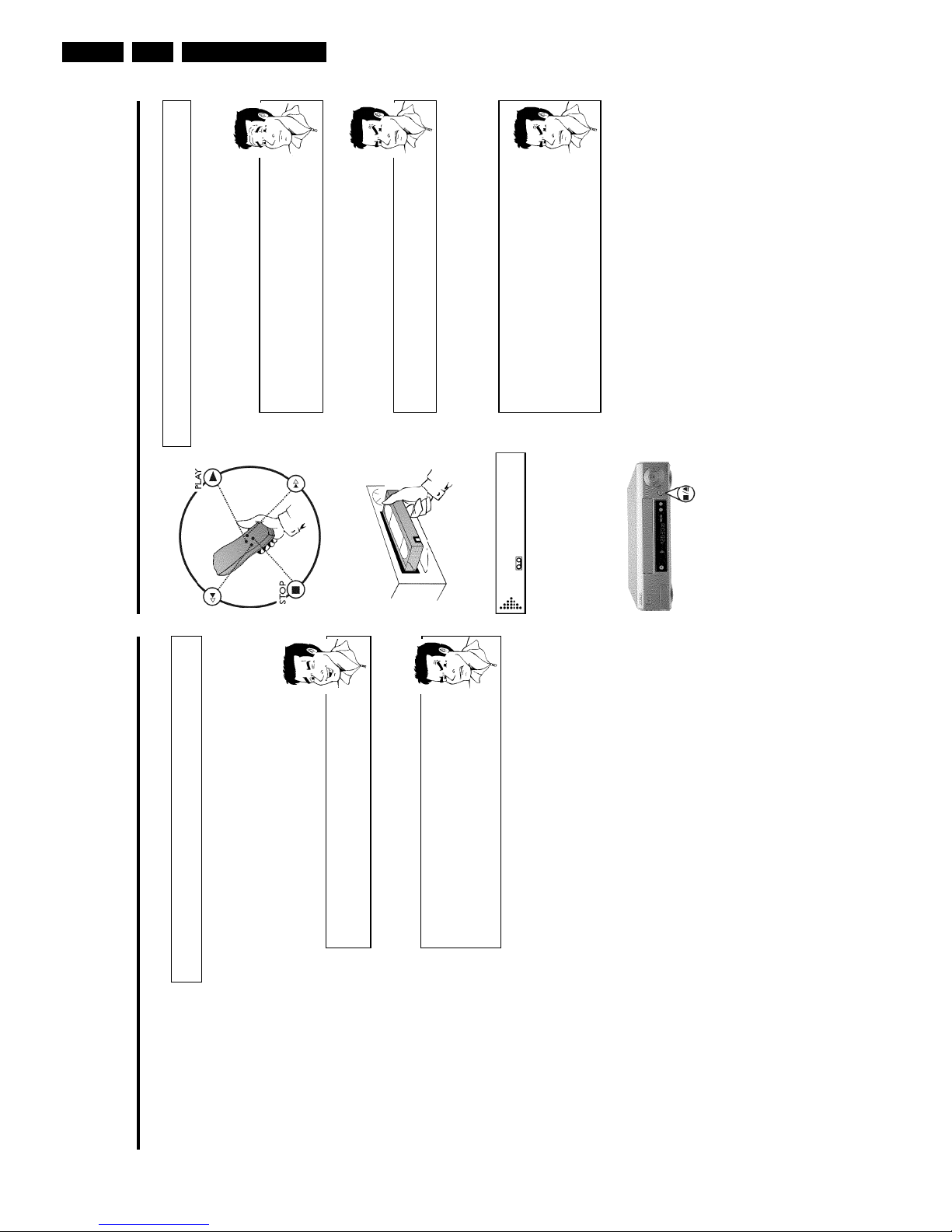
1 Take the remote control and the enclosed batteries (2 batteries).
2 Open the remote control's battery compartment and place the
batteries in it as shown in the picture and close the battery
compartment.
The remote control is now ready to use. Its range is approximately 5 meters.
Connecting your video recorder to the TV
set
The necessary cable connections must be made before you can record or playback TV
programmes using your video recorder.
We recommend that you use a scart cable to connect your TV set and video recorder.
What is a scart cable?
The scart or Euro AV cable serves as the universal connector for picture,
sound and control signals. With this type of connection, there is practically no
loss of quality during the picture or sound transfer.
When you install your video recorder for the first time, select one of the following options:
'Connecting with a scart cable'
If your TV set has a scart socket and you are using a scart cable.
'Connecting without a scart cable'
If you do not wish to use a scart cable.
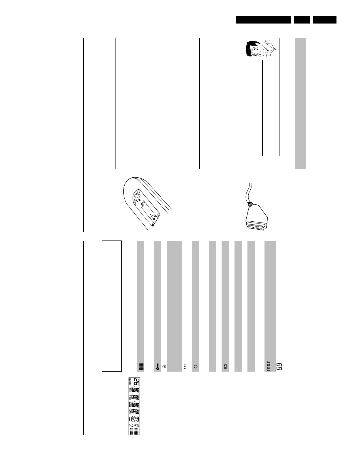
The symbols on your video recorder
display
These symbols can light up on your video recorder display:
This is where the current operating mode is shown as a symbol.LPWhen you have switched on the LP (Long Play) function or when you
play a tape that has been recorded in LP (Long Play).
When you have switched on the child lock.
When a satellite recording has been programmed.
DEC
When a decoder has been allocated to the TV channel (currently
selected programme number on the video recorder) you have currently
selected on the video recorder.
When you play a cassette that has been recorded with hifi sound, or
when a hifi sound is transmitted.
When you are making a recording.kWhen you have programmed a recording or when a programmed
recording is being made.DWhen you are programming daily recordings.WWhen you are programming weekly recordings.
When you have put a cassette in the video recorder.
DATE
When the date of the programmed recording is shown.
START
When the start time of the programmed recording is shown.
PROG.
When the programme number of the programmed recording is shown.
END
When the end time of the programmed recording is shown.
VPS/PDC
Video Programming System / Programme Delivery Control: when a VPS
or PDC code is being transmitted.
Display of programme number of the TV channel / tape position /
channel name / function.
Tape position in seconds.
Direction for use
GB 18 VR1203.
CONGRATULATIONS
YOU NOW OWN A NEW
PHILIPS
VIDEO RECORDER
CONTINUEpOK
aMy screen is empty
b Many TV sets are switched to the programme number for the scart socket
by way of a control signal sent through the scart cable.
b If the TV set does not automatically switch to the scart socket programme
number, manually change to the corresponding programme number on your
TV set (see your TV's operating instructions).
Then, read the paragraph 'Initial installation' in the chapter 'Installing your video recorder'.
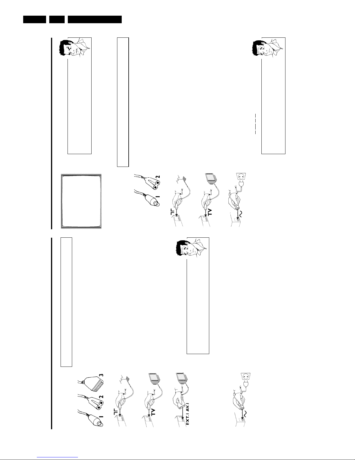
Connecting without a scart cable
Have the following cables ready:
an aerial cable (1, supplied), a mains cable (2, supplied).
1 Switch off your TV set.
2 Remove the aerial cable plug from the aerial input socket of the TV
set. Insert it into the socket 2 at the back of the video recorder.
3 Insert one end of the supplied aerial cable into the socket 3 at the
back of the video recorder and the other end into the aerial input
socket at the back of the TV set.
4 Insert one end of the supplied mains cable into the mains socket
4 at the back of the video recorder and the other end into the wall
socket.
5 Switch on your TV set and select the programme number used for
video playback on your TV set (see your TV's operating instructions).
Which programme number is used for video recorder operation?
To ensure the stability of the television picture during cassette playback
(prevention of waves or streaks), special programme numbers have been set
aside on the TV for the use of video recorders. This is usually the highest
possible programme number, e.g. '12', '16', '99' or even programme number
'0'. For more information, please see your TV's operating instructions.
Connecting with a scart cable
Have the following cables ready:
an aerial cable (1, supplied), a mains cable (2, supplied), a scart cable (3).
1 Remove the aerial cable plug from your TV set. Insert it into the
socket 2 at the back of the video recorder.
2 Insert one end of the supplied aerial cable into the socket 3 at the
back of the video recorder and the other end into the aerial input
socket at the back of the TV set.
3 Plug one end of a scart cable into the scart socket EXT.1 AV 1 at
the back of the video recorder and the other end into the suitable
scart socket on your TV set (see your TV's operating instructions).
My TV set has several scart sockets. Which one should I use?
Select that scart socket which is suited for the video output as well as for the
video input.
My TV offers me a selection menu for the scart socket.
Select 'TV' as a connection source of this scart socket.
4 Switch on the TV set.
5 Insert one end of the supplied mains cable into the mains socket
4 at the back of the video recorder and the other end into the wall
socket.
6 If the connection was properly made and your TV was automatically
switched to the programme number for the scart socket, e.g. 'EXT',
'0', 'AV', you will see the following picture:
Direction for use
GB 19VR120 3.
Installing your video recording
Initial installation
This chapter shows you how to start the initial installation. The video recorder automatically
seeks out and stores all available TV channels.
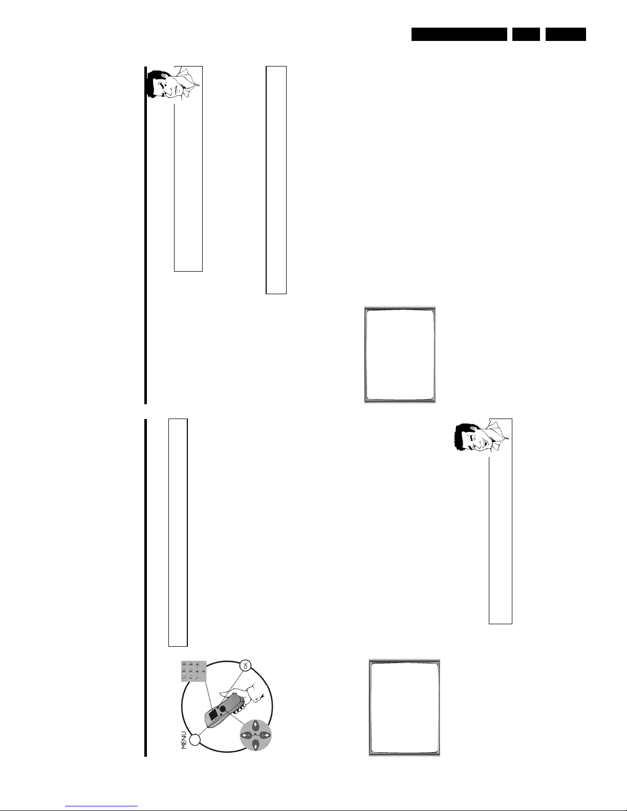
'Aim' correctly
In the following sections, you require the remote control for the first time.
When using, always aim the front of the remote control at the video recorder
and not at the TV set.
Connecting additional devices
After you have connected additional devices (satellite receiver, etc.) through
the aerial cable, switch them on. The automatic channel search will recognise
them and save them.
1 Confirm the image on the TV screen by pressing the OK button on
the remote control.
2 Select the desired language for the on-screen menu by pressing
P r= or ;qP .
What is an onscreen menu?
The multi-language on-screen menu takes the mystery out of using your new
video recorder. All settings and/or functions are displayed on your TV screen
in the corresponding language.
3 Confirm with OK .
4 Select the country of your residence with P r= or ;qP .
If your country does not appear, select 'OTHERS'.
Confirm with OK .
aThe video recorder does not find any TV channels during the
search
b Select channel 1 on the TV set. Can you see the saved TV channel on the
TV set?
If not, check the cable connection of the aerial (aerial socket), video
recorder, TV set.
b Please have patience.
The video recorder searches the entire frequency range in order to find
and save the largest possible number of TV channels. It is possible that the
TV channels in your country are broadcast in a higher frequency range. As
soon as this range is reached during the search, the video recorder will find
the TV channels.
CLOCK
YEAR è 2001 p
MONTH 01
DATE 01
TIME 20:00
SMART CLOCK ON
________________________________
EXITpMENU STOREpOK
5 When the automatic TV channel search is complete, 'STORED' will
briefly appear on the TV screen.
'YEAR', 'MONTH', 'DATE', 'TIME' will appear on the TV screen.
6 Check the year in line 'YEAR'. If required, please change the year with
the number buttons 0-9 on the remote control.
6 Select this programme number and manually start the TV's channel
search as if you wanted to save a new TV channel until the 'test
image' appears.
CONGRATULATIONS
YOU NOW OWN A NEW
PHILIPS
VIDEO RECORDER
CONTINUEpOK
aI do not see a 'test screen'
b Check the cable connections.
b The video recorder 'transmits' on the 591MHz frequency (channel 36)
Repeat the channel search on your TV set.
7 Save this programme number setting on your TV set for video
recorder operation.
Programme number for video recorder operation
You have now saved a programme number for use by your video recorder as
you would a regular TV channel. This programme number must now be used
in future for video recorder playback ('video recorder' TV channel).
You can find more details in chapter 'Initial Installation'.
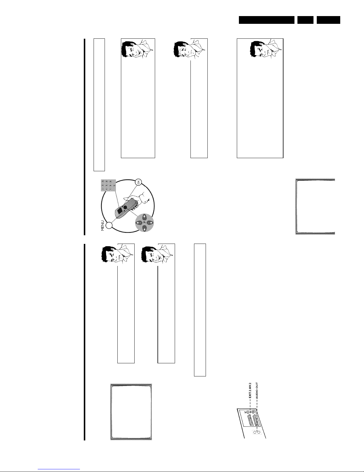
Connecting additional devices
You can connect additional devices such as decoders, satellite receivers, camcorders, etc. to the
socket EXT.2 AV 2 .
Two audio sockets AUDO OUT L R are located on the back of the video recorder (audio
signal output left/right). These can be used to connect stereo systems.
Direction for use
GB 20 VR1203.
4 Use the buttons ;qP or P r= to select the line 'MANUAL
SEARCH' and confirm with OK .
MANUAL SEARCH
PROGRAMME NUMBER è P01 p
S-CHANNEL NO
CHANNEL NUMBER 21
DECODER OFF
NICAM ON
TV SYSTEM AUTO
________________________________
EXITpMENU STOREpOK
5 Use the buttons P r= or ;qP to select the line 'DECODER'.
6 Use the buttons Q or P to select 'ON' (Decoder switched on).
How can I switch off the decoder?
Use the button
P
on the screen to select 'OFF' (Decoder switched off).
7 Confirm with OK .
8 End with the button MENU .
BBC1
The decoder has now been allocated to this TV channel.
If this TV channel is chosen, the symbol 'DEC' will appear in the video recorder display.
Manual TV channel search
In some cases it could occur that all of the TV channels were not found and saved during
the
initial installation. In this case, the missing or coded TV channels must be searched for
and
stored manually.
1 Switch on the TV set. If required, select the programme number for
the video recorder.
2 Press MENU on the remote control.
The main menu will appear.
3 Select line 'MANUAL SEARCH' using P r= or ;qP and confirm with
OK .
MANUAL SEARCH
PROGRAMME NUMBER è P01 p
S-CHANNEL NO
CHANNEL NUMBER 21
DECODER OFF
NICAM ON
TV SYSTEM AUTO
________________________________
EXITpMENU STOREpOK
4 Select line 'PROGRAMME NUMBER' using P r= or ;qP .
5 Using Q or P , select the desired programme number that you
want to use for the TV channel, e.g. 'P01'.
6 In line 'S-CHANNEL', select the desired display using P .
7 Select the next line with ;qP or P r= .
8 Check if the displayed settings for 'MONTH', 'DATE' and 'TIME' are
correct.
9 When all information is correct, save by pressing OK .'STORED' will
briefly flash in the video recorder display.
The initial installation is now complete.
Satellite receiver
If you are connecting a satellite receiver, please read the section 'Using the
satellite receiver'.
Decoder
If you are connecting a decoder, you must install it as described in the next
section.
aSound disruptions can occur on several TV channels
b If sound disruptions should occur for several saved TV channels or there is
no sound at all, it is possible that the incorrect TV system was saved for
this TV channel. In the chapter 'Manual TV channel search' you will find the
information on how to change the TV system.
Decoder allocation
Some TV channels transmit encoded TV signals which can only be viewed with a commerc
ially
purchased or hired decoder without disturbances. You can connect such a deco
der
(descrambler) to this video recorder. The following function will automatically activate
the
connected decoder for the desired TV channel.
1 Switch the TV on. If applicable, select the programme number for the
video recorder operation.
2 Use the buttons ;qP , P r= on the video recorder or the number
buttons 0-9 on the remote control to select the TV channel which
you would like to allocate the decoder to.
3 Press the button MENU on the remote control. The main menu will
appear.
Direction for use
GB 21VR120 3.
Using the satellite receiver
TV channels from a satellite receiver (connected to the scart socket EXT.2 AV 2 ) are received
on the video recorder on programme number 'E2'.
To do this, select programme number 'E1' with 0 on the remote control and then select
programme number 'E2' with P r= .
You should select the TV channels to be received by the satellite receiver directly on the
receiver itself.
Sorting TV channels automatically
(Follow TV)
When the automatic channel search function is activated, the TV channels are saved in a specific
order. This may vary from the order of TV channels on the TV set.
This function changes the order of TV channels saved in the video recorder to match that of the
TV set.
This only works if the video recorder (socket EXT.1 AV 1 ) and the TV set are connected
with a scart cable.
1 Switch on the TV set. If required, select the programme number for
the video recorder.
2 Press the MENU button on the remote control. The main menu will
appear.
MENU
CLOCK
AUTO TUNING
MANUAL SEARCH
FOLLOW TV
TV CHANNEL ALLOC.
RECORD SPEED
AUTO STANDBY
VIDEOSYSTEM
LANGUAGE
SPECIAL SETTINGS
________________________________
…EXITpMENU OK
†HOTLINEpCL
3 Select line 'FOLLOW TV' using P r= or ;qP and confirm with
OK .
4 Press the OK button. 'TV01' will appear in the video recorder display.
TV01
5 Select programme number '1' on the TV set.
What is hidden behind the settings?
'NO': Display/Entry of channels
'YES': Display/Entry of special channels
What is a special channel?
TV channels are transmitted in certain pre-defined frequency ranges. These
ranges are divided into channels. A specific frequency/channel is assigned to
each TV station. Certain frequency ranges are specified as special channels
(hyperband channels).
7 In line 'CHANNEL NUMBER', enter the channel of the desired TV
station using the number buttons 0-9 .
aI don't know the channels for my TV stations
b In this case, press
P
in line 'CHANNEL NUMBER' to start the automatic
channel search. A changing channel number will appear on the TV screen.
Continue the automatic search until you have found the desired TV
channel.
What is NICAM?
NICAM is a digital sound transmission system. Using NICAM, you can
transmit either 1 stereo channel or 2 separate mono channels. However, if
you experience poor reception resulting in sound disruptions, you can turn off
NICAM.
In line 'NICAM', select 'OFF' using
Q
or
P
.
How can I change the TV transmission system of the TV channel?
In line 'TV SYSTEM', select the corresponding TV system using
Q
or
P
until the picture/sound disruptions are minimised.
8 Save the TV channel with OK .'STORED' will briefly appear on the
TV screen.
9 To search for other TV channels, begin again at step
3
.
0 To end, press MENU .
Direction for use
GB 22 VR1203.
Automatic TV channel search
During installation, all available TV channels are searched for and saved. If the cha
nnel
assignments of your cable or satellite TV provider change or if you are reinstalling the v
ideo
recorder, e.g. after moving house, you can start this procedure again. This will replace theTVchannels already saved with the new ones.
1 Switch on the TV set. If required, select the programme number for
the video recorder.
2 Press the MENU button on the remote control. The main menu will
appear.
3 Select line 'AUTO TUNING' using P r= or ;qP .
4 Press OK .
5 Select the country of your residence with ;qP or P r= .
If your country doesn't appear, select 'OTHERS'.
6 Press OK .
AUTO TUNING
SEARCHING
00 TV CHANNELS FOUND
ƒƒƒƒƒƒƒ__________________
PLEASE WAIT...
7 The automatic TV channel search starts. This allows the video
recorder to save all available TV channels. This procedure may take
several minutes.
8 When the TV channel search is complete, 'STORED' will briefly appear
on the TV screen.
9 To end, press MENU .
You can read about how to search for a TV channel manually in the section 'Manual TV cha
nnel
search'.
Monitor function
You can switch back and forth between the TV picture and video recorder picture
with
MONITOR . But this only works when you use a scart cable to connect the video recorde
rto
your TV set and your TV set responds to this switch-over.
aI cannot switch my TV set to programme number '1'
b If you have connected additional devices to socket
EXT.2 AV 2
, please
disconnect these devices. Because of other connected devices, the TV set
could switch to the programme number of the scart socket.
6 Confirm with OK on the video recorder remote control. The video
recorder compares the TV channels on the TV set and the video
recorder.
If the video recorder finds the same TV channel as on the TV set,
then it stores it at 'P01'.
a'NOTV' will appear in the display. The video recorder is not
receiving a video signal from the TV set.
b Check the plug on the scart cable.
b Check your TV's operating instructions to see which scart socket is used
for video signals.
b If this does not help, it's not possible to use this function.
Please read the section 'Sorting TV channels manually'.
7 Wait until the next number, e.g. 'TV02' appears in the display.
8 Select the next programme number on the TV set, e.g. '2'.
9 Confirm with OK on the video recorder remote control.
Deleting sorting
You can delete an incorrect TV channel sorting by pressing
CLEAR (CL)
.
0 Repeat steps
7
to
9
until you have assigned a programme number
to all TV channels.
A To end, press MENU .
Direction for use
GB 23VR120 3.
aThe main menu will appear on the screen
b After you have confirmed the last channel that can be sorted, you will
automatically return to the main menu since no more TV channels can be
assigned.
0 To assign other TV channels to a programme number, repeat steps
7
to
9
.
A Confirm the assignment of the TV channel with MENU .
B To exit the main menu, press MENU .
Setting onscreen menu language
You have the option of setting one of the displayed languages for the on-screen menu (OSD).
However, the video recorder display will only display English text regardless of this setting.
1 Switch on the TV set. If required, select the programme number for
the video recorder.
2 Press MENU on the remote control. The main menu will appear.
MENU
CLOCK
AUTO TUNING
MANUAL SEARCH
FOLLOW TV
TV CHANNEL ALLOC.
RECORD SPEED
AUTO STANDBY
VIDEOSYSTEM
LANGUAGE
SPECIAL SETTINGS
________________________________
…EXITpMENU OK
†HOTLINEpCL
3 Select line 'LANGUAGE' and confirm with OK .
4 Select the desired language with P r= or ;qP and confirm with
OK .
'STORED' will appear briefly on the screen.
5 To end, press MENU .
Sorting and clearing TV channels manually
After you have performed the automatic channel search you may not agree with the sequence in
which the individual TV channels have been allocated to the programme positions (programme
numbers) of the video recorder. You can use this function to individually sort the TV channels
already saved or to delete unwanted TV channels or those with poor reception.
1 Switch on the TV set. If required, select the programme number for
the video recorder.
2 Press MENU on the remote control. The main menu will appear.
3 Select line 'TV CHANNEL ALLOC.' using P r= or ;qP .
4 Confirm with OK .
TV CHANNEL ALLOC.
ALLOCATE ON P01
TV CHANNEL è CNN p
________________________________
ALLOCATEpOK EXITpMENU
5 Using Q or P , select the saved TV channel that you want to
assign to the programme number 'P01'.
6 Confirm with OK . The following message will briefly appear on the
TV screen: 'ALLOCATED ON P01'.
7 Then the sorting for the next highest programme number will appear
on the screen, e.g. 'ALLOCATE ON P02'.
8 Using Q or P , select the saved TV channel that you want to
assign to this programme number, e.g. 'P02'.
Deleting TV channels
Using
CLEAR (CL)
you can delete unwanted TV channels or those with
poor reception.
9 Confirm with OK . The following message will briefly appear on the
TV screen: 'STORED'.
Direction for use
GB 24 VR1203.
Important notes for operation
Switching on
You can switch on the video recorder with the STANDBY/ON m button, the number button
s
0-9 or by putting in a cassette.
Automatic switchoff
If the video recorder is not used for several minutes, it switches itself off automatically. Thisfunction can be deactivated (e.g. if you want to use the video recorder as a TV receiver). For moreinformation, please read the section 'Automatic switch-off' in chapter 'Additional functions'.
Time in the display
If you have switched the video recorder off with STANDBY/ON m , the time will show in thedisplay, e.g. '18:00'.
If the clock has not been set, '--:--' will appear.
When the video recorder is switched off and the time isn't shown in the video recorder display,the clock display may be switched off. You will find more information in the chapter 'Additionalfunctions' section 'Switch off the clock display'.
Energy consumption
The video recorder should always be connected to the mains so as not to affect the use of the TVor programmed recordings.
Your video recorder uses less than 4W (with clock display switched off).
Power outage/no
power
Channel information remains saved for up to 1 year, the time and timer information is saved for upto 3 hours.
Emergency exit
The video recorder and the remote control have the option of an 'Emergency exit'. You can usethe STANDBY/ON m button to interrupt any function or step during use.
You can operate your device without worry. There is no risk whatsoever of damaging the vide
o
recorder by performing user steps incorrectly.
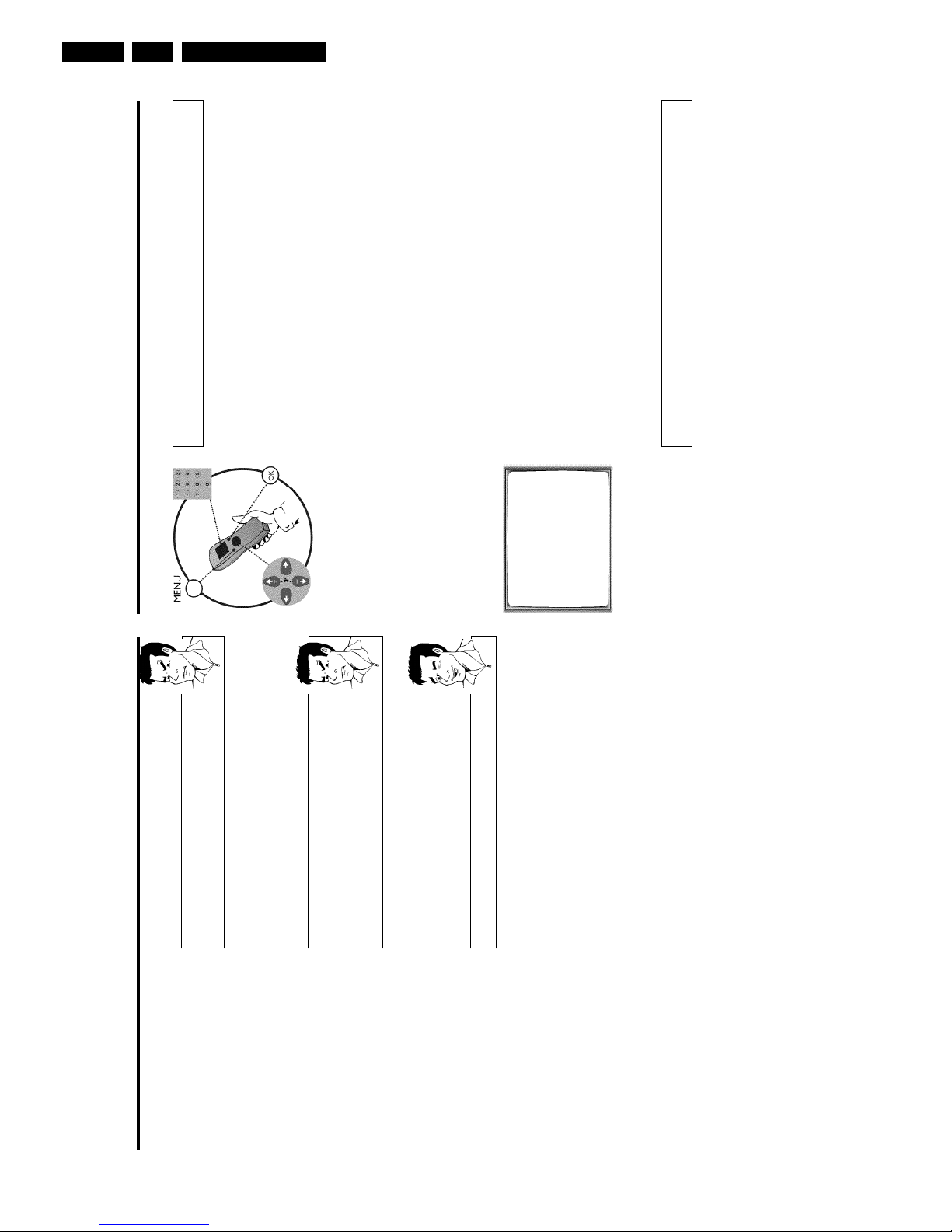
Navigation in the screen menu
You can check/change many functions and settings of your video recorder via the screen m
enu.
The individual functions are selected as follows:
MENU
CLOCK
AUTO TUNING
MANUAL SEARCH
FOLLOW TV
TV CHANNEL ALLOC.
RECORD SPEED
AUTO STANDBY
VIDEOSYSTEM
LANGUAGE
SPECIAL SETTINGS
________________________________
…EXITpMENU OK
†HOTLINEpCL
Call up the menu: with MENU .
To select: with P r= or ;qP .
To enter or change your selection: with the number buttons 0-9 or with Q or P .
To save or confirm: with OK .
To cancel: with STANDBY/ON m .
To end: with MENU .
Setting the time and date
If the display shows an incorrect time or '--:--', the time and date must be reset manually.
If a TV channel which transmits TXT/PDC (teletext/PDC) is stored under programme num
ber
'P01', time/date will automatically be taken from the TXT/PDC information. (SMART CLOCK
)
1 Switch on the TV set. If required, select the programme number for
the video recorder.
2 Press MENU on the remote control. The main menu will appear.
3 Select line 'CLOCK' using P r= or ;qP and confirm with OK .
CLOCK
YEAR è 2001 p
MONTH 01
DATE 01
TIME 20:00
SMART CLOCK ON
________________________________
EXITpMENU STOREpOK
4 Check the year in line 'YEAR'. If required, please change the year with
the number buttons 0-9 on the remote control.
5 Select the next line with ;qP or P r= .
6 Check 'MONTH', 'DATE' and 'TIME' in the same way.
aTime/date is displayed incorrectly despite manual setting
b With Smart Clock, time/date is transferred from the TV channel saved on
'P01' and automatically corrected.
Switch off Smart Clock. In line 'SMART CLOCK', select 'OFF' using
Q
or
P
.
You can switch on 'SMART CLOCK' again when you select 'ON'.
7 Check the displayed settings and confirm with OK .
'STORED' will appear briefly on the screen.
8 To end, press MENU .
Direction for use
GB 25VR120 3.
Why must I note the cassette number?
When searching for available recordings, you will need to insert the
corresponding cassettes (cassette numbers).
How many cassettes can I save in the Tape List?
You can store up to 9 cassettes. You can store a maximum number of 50
titles in the Tape Manager.
Editing recording titles
In the Tape List, all recordings longer than 10 minutes are displayed with cassette number,
recording title and length of recording. The TV channel, time and date are saved as a title. The
title of this recording can only be changed after the recording has been completed.
To do this, the corresponding cassette does not have to be in the video recorder. In the
following, you will read how to customise the titles to your wishes.
1 Press TAPE LIST on the remote control. An overview of all saved
titles/cassettes from the Tape List appears on the screen.
aI can see the message 'TAPE LIST- MEMORY EMPTY'
b There are no recordings saved in the Tape List. Therefore, it is not
possible to add or change a title.
2 Using ;qP or P r= select the title to be edited and confirm with
P .
3 Using P or Q select the position where the letter/number/symbol
is to be changed or re-entered.
4 Change the desired symbol using ;qP or P r= .
Deleting symbols
To delete a symbol of a recording title, press
CLEAR (CL)
at the
corresponding symbol position.
5 Repeat step
3
and step
4
until you have made the desired changes.
6 Save the new title with OK .
7 If you want to change more titles, repeat step
3
through step
7
.
8 To end, press TAPE LIST .
Tape List
General information
The 'Tape List is an integrated database in the video recorder that remembers all recordings
made by this video recorder. The Tape List helps you keep track of which film is on which
cassette. The 'Tape List' also gives you quick and easy access to recordings.
And: If desired, the video recorder will rewind to the beginning of the selected recording and
automatically start playback.
Can I add cassettes that already have recordings on them to the
Tape List?
Yes. Tape List can manage a maximum of 9 cassettes. However, there must be
recordings on the cassettes in order to copy them to the Tape List database.
Adding a cassette to the Tape List
You can add any cassette to the 'Tape List'. Please note that the process for adding cassettes
that already have recordings on them lasts longer than with new (blank) cassettes.
1 Switch on the TV set. If required, select the programme number for
the video recorder.
2 Label the cassette to be inserted with a number from 1 to 9.
3 Insert the cassette into the video recorder.
4 'TAPE' will appear in the display.
5 Enter the cassette number using the 0-9 number buttons on the
remote control.
The video recorder will briefly check the cassette inserted.
'CHECKING CASSETTE' appears on the TV screen.
If the cassette is new (blank), no information will appear on the
screen.
aI see a cassette number and an overview of all recordings on this
cassette
b You have selected a number which has already been included in the Tape
Manager and contains a recording.
On the screen after 'CHECKING CASSETTE' I see the message ''
There are already recordings on the cassette. This cassette is searched for
recordings and added to the Tape List.
Direction for use
GB 26 VR1203.
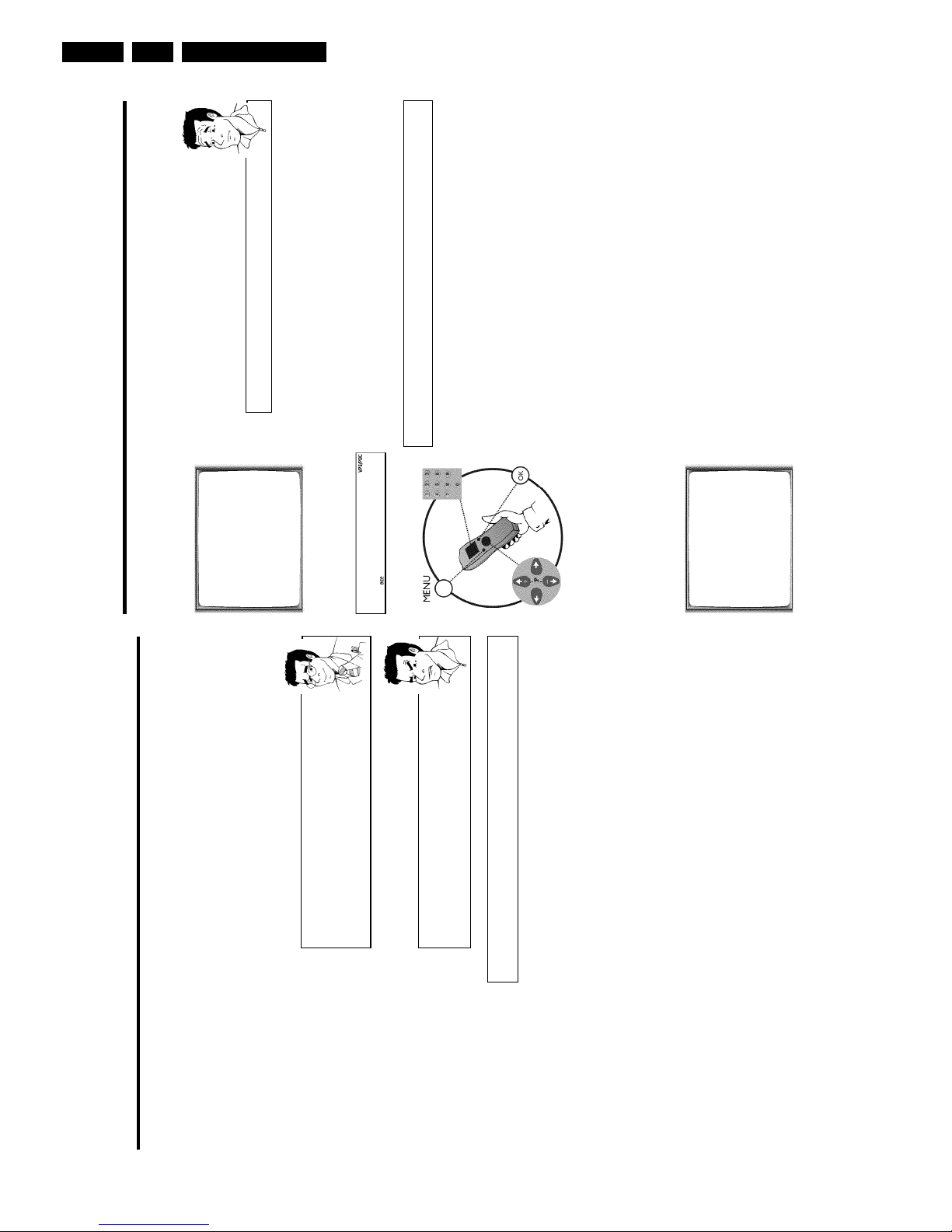
Playback
Playing cassettes
You can use this video recorder to play back recorded VHS video cassettes. You can ope
rate
the video recorder using the remote control or the buttons on the front of the video record
er.
What does VHS mean?
'Video Home System' (VHS) has become the world-wide standard for the
playback and recording of amateur video cassettes. This popular standard
continues to be improved. Super VHS (S-VHS) provides a sharper picture and
less noise. Digital VHS (D-VHS) only works with digital picture and sound
signals. Your video recorder can only record and play standard VHS cassettes.
1 Put a cassette into the cassette slot.
The cassette is inserted automatically. ' v ' will appear on the display.
aI see 'TAPE' in the display
b The video recorder is waiting for you to enter a cassette number from the
'Tape List'. You can find more information on the Tape List in the chapter
'Tape List'.
2 Press the Play button PLAY G to view the tape.
This will, for example, appear in the display:
0:00:
02
aPicture/ sound quality is poor
b When playing rental videos or older, poorer quality cassettes, it may not be
possible to completely filter out picture and sound interference. This is not
a fault in your machine.
Please read the section 'Selecting the picture settings (SMART PICTURE)',
or the chapter 'Eliminating picture interference'.
b During playback the automatic TV system will switch-over automatically. If
picture/sound interference occurs, attempt to fix the problem by manually
switching the TV system. In that case, turn to chapter 'Additional functions'
section 'Switching the video (color) system'.
3 To stop the playback, press STOP h on the remote control or
STOP/EJECT ? on the video recorder.
4 To eject the cassette, press STOP/EJECT ? on the video
recorder when the video recorder stops the playback (STOP).
To eject a cassette, you can also use EJECT J on the remote
control.
Searching for a title in the Tape List
This function can be used to quickly and easily find and play back a recording saved in the T
ape
List. The video recorder automatically rewinds to the beginning of the selected recording
and
automatically starts playback.
1 Press TAPE LIST on the remote control.
2 An overview of all recordings saved in Tape List appears on the
screen.
What do the displays on the screen mean?
'CASS.' = Cassette number
'TITLE' = Title (TV channel, time, date)
'LENGTH' = Length of the recording
3 Select the title that you want to play back with P r= or ;qP .
aI see the message 'INSERT CASSETTE X' on the screen.
b The selected recording is located on the Tape List cassette with the
displayed cassette number. Please insert the corresponding cassette. After a
brief check, the video recorder will rewind to the beginning of the selected
recording and start playback.
aI want to cancel the search
b If you want to cancel the search, press
MENU
.
4 Confirm with OK . The video recorder winds to the start of the
selected recording and automatically starts playback.
Direction for use
GB 27VR120 3.
aThe counter does not move
b This occurs when there are no recordings on a portion of a tape.
Therefore, the video recorder cannot receive any information from the
tape. This is not a fault in your machine.
aThe display/the screen shows '-0:01:20'
b If you rewind a cassette from the tape position '0:00:00', the counter will
show for instance, '-0:01:20' (the cassette will be rewound to 1 minute
and 20 seconds before '0:00:00').
a':' is displayed in the 'REMAIN' counter
b This counter will automatically recognise the length of the tape. In addition,
when you put in a cassette the video recorder must first calculate the time
played. Therefore, '-:--' appears first and only after the tape has been
running for a few seconds will the correct playing time be shown.
Searching for a tape position with picture
(scanning)
0:30:
21
1 While a cassette is playing, press H (reverse) or I (forward) one
or more times. This will, for example, appear in the display:
2 To stop at a certain place on the tape, press PLAY G .
Decreased picture quality
Scanning interferes with the picture quality. The sound is switched off. This is
not a fault in your machine.
Still picture / slow motion
0:00:
02
1 During playback, press STILL R to stop the tape and display a still
picture. This will, for example, appear in the display:
2 Each time you press STILL R , the picture will advance one frame.
3 When you hold down the STILL R button, the tape will be played
in slow motion.
4 When you press I several times, you have a choice of several
playback speeds for slow motion.
5 To continue playback, press PLAY G .
Automatic switchoff of special functions
Many functions (e.g. pause, still picture, search) switch themselves off
automatically after a short time in order to protect the cassette and to save
energy.
Do I need to change the playback speed when playing back LP
recordings?
For playback, the correct recording speed 'SP' will automatically be selected.
For more information, please read the section 'Selecting the recording speed
(SP/LP)' in the chapter 'Manual recording'.
Playing back NTSC cassettes
Cassettes that have been recorded in the NTSC standard (for example, American cassettes) can
be played back using this video recorder. However, this only works on PAL-television sets which
are suitable for a picture frequency of 60Hz.
When you play an NTSC cassette '60HZ' will appear on the display.
Some special features (for example, still picture) are not possible while you are playing an NTSC
cassette.
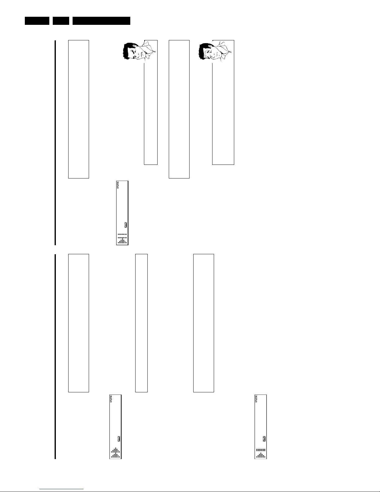
Displaying current tape position
The display shows the tape position in hours, minutes and seconds. In addition, by pressing
OK you can show the present tape position on the TV screen.
The following information is displayed on the screen:
e.g.: 0:02:45 Shows the tape position in hours, minutes and seconds.
Moving/blinking arrow: This indicates the current tape position. The arrow moves in a line from
left (tape start) to right (tape end).
'REMAIN 0:06': will show the actual amount of playing/recording time left on the tape in hours
and minutes.
When you play an NTSC cassette, the video recorder will not show 'REMAIN 0:06'.
How can I set the counter to '0:00:00'?
You can set the counter to '0:00:00' using
CLEAR (CL)
.
When you put a cassette in the machine, the counter will automatically reset
to 0:00:00'.
Direction for use
GB 28 VR1203.
Automatic search for a blank space on the
tape
You can search for space on the tape (at least 1 minute of blank tape) for a new recording
, for
example, after an existing recording on the tape.
0:00:
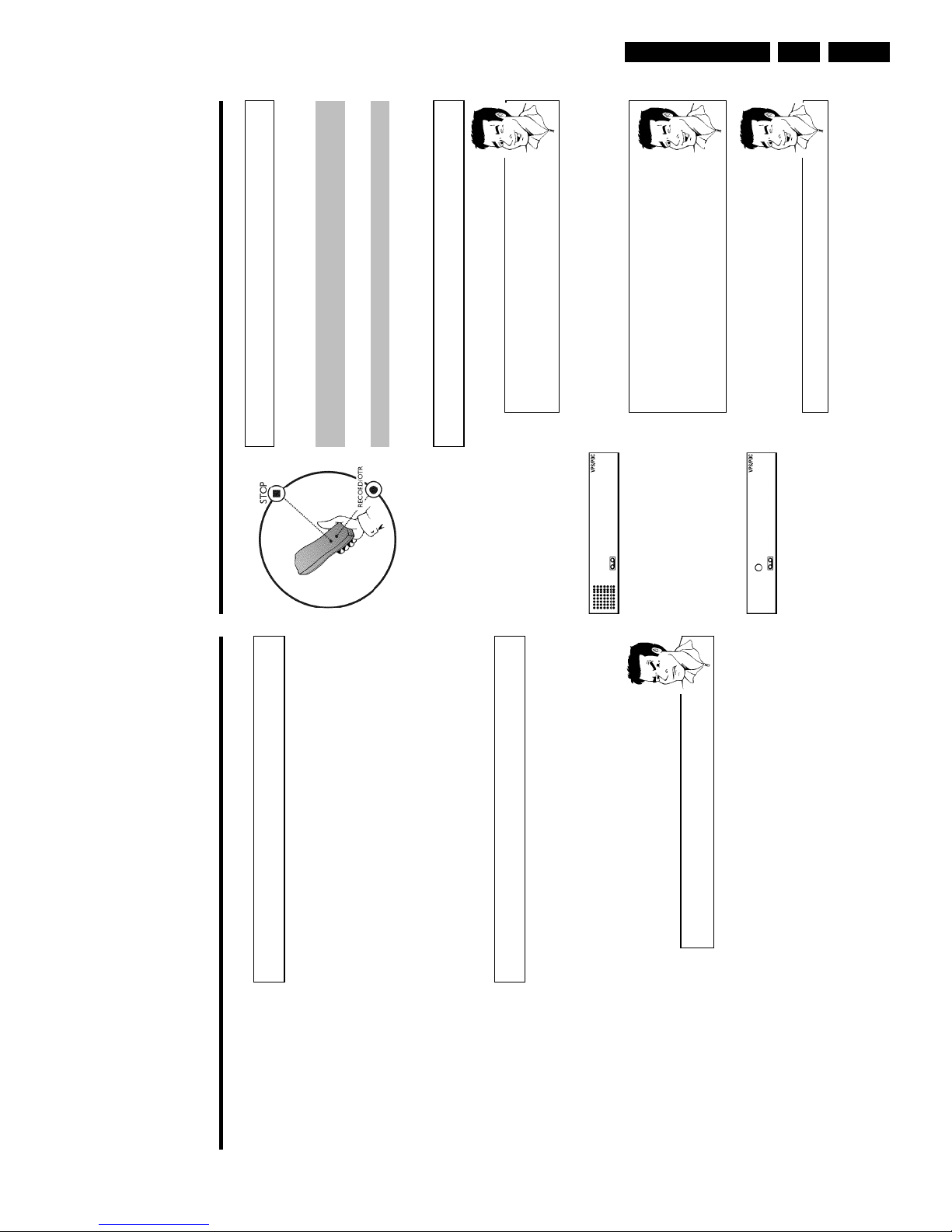
00
1 Press INDEX E . Then press STOP h . This will, for example,
appear in the display:
2 As soon as the video recorder finds the corresponding tape position,
it automatically switches to pause.
aThe cassette is ejected
b The video recorder was unable to find any blank space on the tape
inserted.
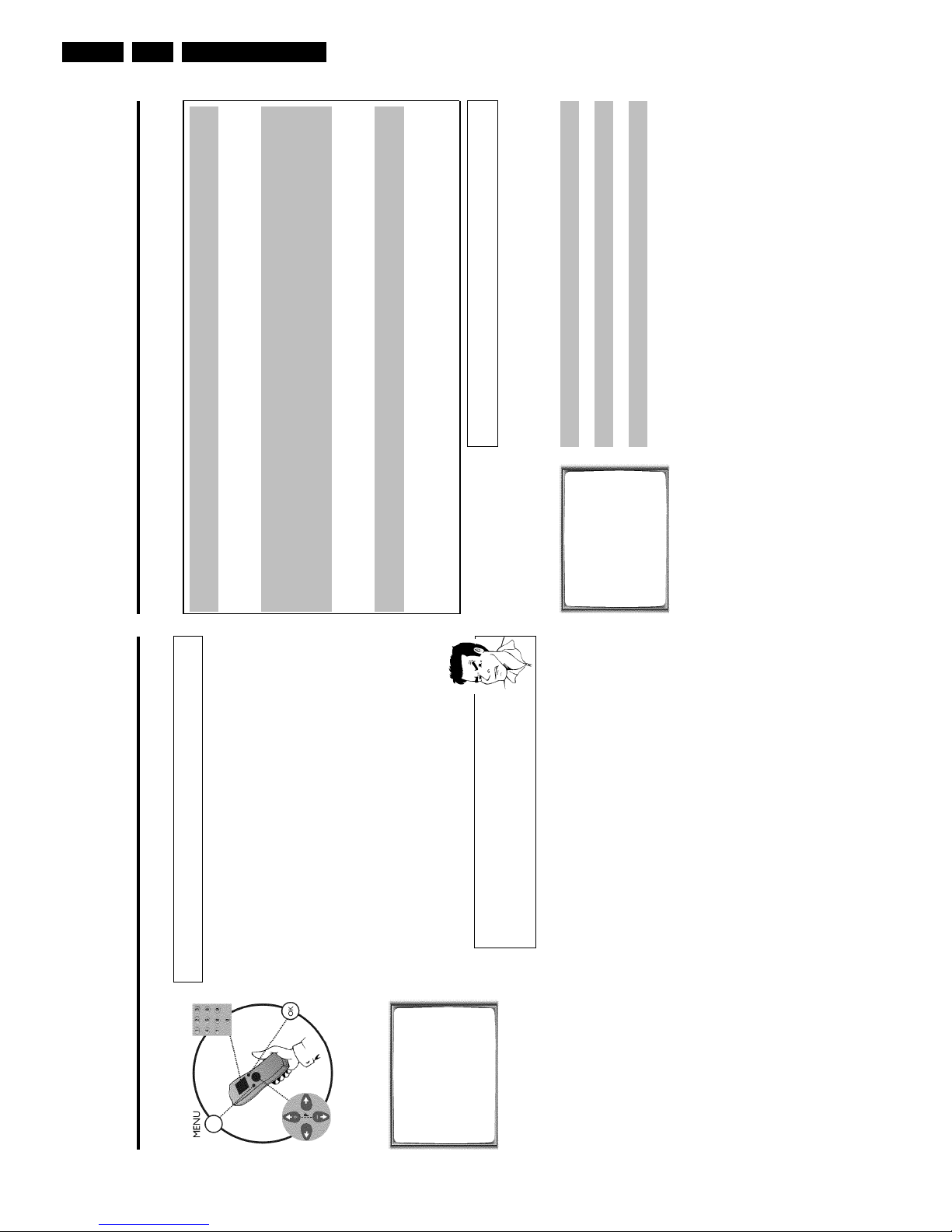
Selecting picture settings (SMART
PICTURE)
Using SMART * , you can display and set many stored picture settings for playback.
What types of picture settings are available to me?
'NATURAL': Natural picture (standard setting)
'DISTINCT': Emphasises details (quick movements, sports)
'SOFT': Suppression of interference (when using rental cassettes)
'SHARP': Increase in sharpness (e.g. for animated films)
1 During playback, press SMART * . This will show the current
picture setting.
Press the SMART * button several times to select the
corresponding picture setting.
2 If the SMART * button is not been pressed after a few seconds,
the selected picture setting will be saved.
3 These picture settings will not change until you eject the cassette.
Searching for tape position without
picture (forward wind and rewind)
1 Stop the tape with STOP h .
0:30:
21
2 Press H (reverse) or I (forward). This will, for example, appear
in the display:
3 To stop at a certain place on the tape, press STOP h .
Instant View
With this function you can switch to picture search during wind and rewind.
1 If you hold H (rewind) or I (wind) during wind or rewind, you
will switch to picture search.
2 As soon as you release the button, the video recorder will
automatically switch back to rewind or wind.
Automatic search for a tape position
(index search)
Every time a tape is recorded an index marking is written on the tape. This marking canbecompared with a bookmark. These marked positions can be found again quickly and easily l
ater
by pressing a button.
1 To search for the previous marking, press INDEX E and then H .
0:30:
02
2 For the next marking, press INDEX E and then I . This will, for
example, appear in the display for the next marking.
3 As soon as the video recorder finds this marking, it automatically
switches to playback.
Direction for use
GB 29VR120 3.
Manual recording
General information
Use 'Manual Recording' to make a spontaneous recording (for example, a programme currently
being shown).
If you want to start and stop a recording manually, read the section 'Recording without
automatic switchoff'.
If you want to start a recording manually but have it stopped automatically, read the section
'Recording with automatic switchoff'. (e.g. not to record to the end of the tape)
Read the section 'Direct record' if you want to record a programme currently being shown.
Read the section 'Automatic recording from a satellite receiver', if you want a recording to
be controlled automaticallyby a satellite receiver.
Recording without automatic switchoff
1 Insert a cassette.
Using 'Tape List'
To save a recording in the 'Tape List' or to use a 'Tape List' cassette, enter
the cassette number using the number buttons
0-9
on the remote control.
The cassette is being checked. You can find more information on the 'Tape
List' in the chapter 'Tape List'.
BBC1
2 Use ;qP or P r= to select the programme number you want to
record, for example, 'P01'. This will appear on the display:
Station name
If a TV station transmits a station name, it will be shown in the display.
Programme numbers 'E1''E2'
This programme number is provided for recording from external sources (via
the scart socket
EXT.1 AV 1
,
EXT.2 AV 2
).
Programme number 'E3'
This programme number is used for recording from the audio and video front
sockets.
BBC1
3 To start recording, press RECORD/OTR n on the remote control
or RECORD n on the video recorder. This will, for example, appear
in the display:
Displaying tape position
Using
OK
you can show the tape position in the display.
Eliminating picture interference
Optimising tracking
This video recorder has an automatic tracking function. In order for the video heads to optimally
read the video track of the newly inserted video cassette, the tape speed is slightly corrected
automatically.
In some cases however, interference will still occur.
The following section will explain how to manually adjust the tracking settings.
1 While a cassette is playing, hold ;qP until 'TRAC' (TRACking)
appears in the display.
2 Hold down the buttons ;qP or P r= until the playback quality is
at its best.
3 Wait a few seconds, until 'TRAC' disappears from the display.
These selected picture settings will not change until you eject the cassette.
Optimising still picture
If the still picture vibrates vertically, you can improve the still picture as follows:
1 During still picture, hold ;qP or P r= until the picture quality is at
its best.
'JITT' will appear in the display.
2 When you release the button, 'JITT' will disappear.
The video recorder will store these settings automatically.
aI cannot reach optimal quality for the still picture
b Interference which cannot be alleviated by this function can occur in
cassettes of poor quality or camcorder cassettes .
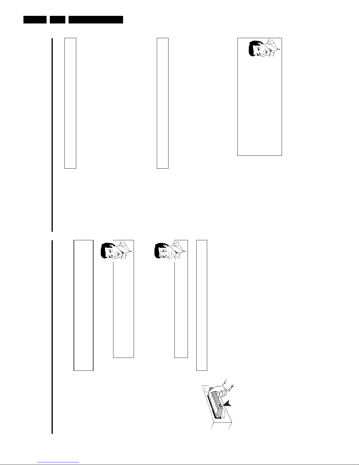
Direction for use
GB 30 VR1203.
Lining up recordings (assemble cut)
When you add a further recording to a cassette, which already has a recording on it, a s
hort
blank (flicker) can appear between the old and the new recording or the picture itself can flic
ker.
To help reduce these from occurring, proceed as follows:
1 Find the tape position of the old recording where you want to insert
the new recording.
2 Look at the last minute of the old recording (playback).
3 Press STOP h on the remote control at the tape position where the
new recording is to go. 9 ' will appear on the display.
4 Now start recording as usual by pressing RECORD/OTR n on the
remote control.
5 Stop recording with STOP h .
Selecting the recording speed (SP or LP)
You can reduce the recording speed by half. This makes it possible to record, for exam
ple,
eight-hours instead of four-hours on an 'E240' (four-hour) cassette.
For playback, the correct recording speed will automatically be selected.
1 Switch on the TV set. If required, select the programme number for
the video recorder.
2 Press MENU on the remote control. The main menu will appear.
3 Select line 'RECORD SPEED' using P r= or ;qP and confirm with
OK .
4 Select the required recording speed with Q or P .
'SP'/'LP' AUTO'
'SP': StandardPlay (normal recording speed) offers the usual first-class picture
quality.
'LP': LongPlay (half recording speed, double recording time). 8 hours can be
recorded on a 4 hour cassette (E240) with a somewhat reduced picture
quality.
'AUTO': AUTOmatic Long Play. If there is not enough space on the tape to
record a programmed recording in standard speed, the recording will
automatically be made in 'LP' (Longplay). Otherwise, the recording speed will
be 'SP' (Standardplay).
4 Stop recording with STOP h .
Recording with automatic switchoff (OTR
OneTouchRecording)
1 Insert a cassette.
Using 'Tape List'
To save a recording in the 'Tape List' or to use a 'Tape List' cassette, enter
the cassette number using the number buttons
0-9
on the remote control.
The cassette is being checked. You can find more information on the 'Tape
List' in the chapter 'Tape List'.
2 Use ;qP or P r= to select the programme number you want to
record.
3 Press RECORD/OTR n on the remote control.
4 Each time you press RECORD/OTR n you will add 30 minutes to
the recording time.
How can I clear the recording time just setted?
To delete an entry, press
CLEAR (CL)
while the display shows the
recording time.
Preventing accidental erasing of cassettes
All cassettes (except for rental and store cassettes) have a security tab on the back of
the
cassette (see arrow).
To prevent recording over important recordings (erasing), you can remove this security taborslide it to the left.
If you later decide to record on a protected cassette, simply cover the hole with adhesive
tape
or slide the tab to the right.
 Loading...