

Philips SAA6750H Datasheet

INTEGRATED CIRCUITS
DATA SH EET
SAA6750H
Encoder for MPEG2 image
recording (EMPIRE)
Preliminary specification
File under Integrated Circuits, IC02
1998 Sep 07

Philips Semiconductors Preliminary specification
Encoder for MPEG2 image recording
(EMPIRE)
CONTENTS
1 FEATURES
2 GENERAL DESCRIPTION
2.1 General
2.2 Function
2.3 Application fields
2.3.1 General
2.3.2 Video editing (PC applications)
2.3.3 Camera signal transmission
2.3.4 DVD authoring
2.3.5 Video recording for surveillance
2.3.6 Digital VCR
3 QUICK REFERENCE DATA
4 ORDERING INFORMATION
5 BLOCK DIAGRAM
6 PINNING
7 FUNCTIONAL DESCRIPTION
7.1 Global architecture description
7.1.1 General
7.1.2 Architecture structure
7.2 Start-up and operation modes
7.2.1 Start-up requirements
7.2.2 Reset processing
7.2.3 Description of operation modes
7.2.4 Pin behaviour
7.3 Video front-end and formatter
7.3.1 General
7.3.2 Data input format
7.3.3 Functional description
7.4 MacroBlock Processor (MBP)
7.4.1 General
7.4.2 Functional description
7.5 Bit stream assembly
7.5.1 General
7.5.2 Pre-packer and packer
7.5.3 Stuffing unit and output buffer
7.6 Data output port
7.6.1 General
7.6.2 Data output format
7.6.3 Functional description
SAA6750H
7.7 Application Specific Instruction-set Processor
(ASIP)
7.7.1 General
7.7.2 ASIP software
7.7.3 GPIO port
7.8 Global controller
7.8.1 General
7.8.2 Functional description
7.9 I2C-bus interface and controller
7.9.1 General
7.9.2 Special considerations
7.9.3 I2C-bus data transfer modes
7.9.4 I2C-bus memories and registers
7.9.5 I2C-bus initialization
7.10 DRAM interface
7.10.1 General
7.10.2 Application hints
7.10.3 Functional description
7.11 FIFO memories
7.12 Clock distribution
7.13 Input/output levels
7.14 Boundary scan test
7.14.1 General
7.14.2 Initialization of boundary scan circuit
7.14.3 Device identification codes
8 LIMITING VALUES
9 THERMAL CHARACTERISTICS
10 CHARACTERISTICS
11 APPLICATION INFORMATION
12 PACKAGE OUTLINE
13 SOLDERING
13.1 Introduction
13.2 Reflow soldering
13.3 Wave soldering
13.4 Repairing soldered joints
14 DEFINITIONS
15 LIFE SUPPORT APPLICATIONS
16 PURCHASE OF PHILIPS I2C COMPONENTS
1998 Sep 07 2

Philips Semiconductors Preliminary specification
Encoder for MPEG2 image recording
(EMPIRE)
1 FEATURES
• Digital YUV input according to
“ITU-T 656”
• NTSC and PAL (720 pixel × 480 lines at 60 Hz and
720 pixel × 576 lines at 50 Hz)
• Integrated colour conversion 4 :2:2to4:2:0
• Integrated format conversion to SIF format (optional)
• Real time MPEG2 Simple Profile at Main Level
(SP@ML) encoding
• IP frame or I frame only encoding supported
• Programmable Group Of Pictures (GOP) size
• Integrated motion estimation, half pixel accuracy,
search range 128 × 128 pixels
• Motion compensated noise reduction
• Elementary stream data output compliant to MPEG2
standard (
• Constant Bit-Rate (CBR) and Variable Bit-Rate (VBR)
supported
• Bitstream output compatible to 16-bit parallel interface
with Motorola (68xxx like) or Intel (xxx86 like) protocol
style
• Adaptable to dedicated applications by embedded
software
• Standard software package available (refer to software
specification)
• No external host processor required
• High speed real time port for processor co-processor
applications
• Only 4 × 4 Mbit external DRAM required
• I2C-bus controlled
• Single external video clock 27 MHz
• Power supply 3.3 V
• Digital inputs 5 V tolerant
• Boundary Scan Test (BST) supported.
“ISO 13818-2”
)
“ITU-T 601”
and to
SAA6750H
2 GENERAL DESCRIPTION
2.1 General
The SAA6750H is a new approach towards a stand-alone
MPEG2 video encoder IC. It combines high quality
SP at ML compliant real time encoding with
cost-effectiveness, allowing for the first time the use of an
MPEG2 encoder IC in applications and markets with a high
cost pressure. This has been achieved by means of a
number of innovations in architecture and algorithms
developed by the Philips Research Laboratories. E.g.:
• The unique motion estimation algorithm supports highly
efficient encoding by using only I frame and IP frame
mode. B frames need not be used. This leads to a
significantly smaller internal circuitry and also reduces
DRAM memory requirements from at least 4 to 2 Mbyte.
In addition, the absence of B frames simplifies editing of
the compressed data stream.
• The patented, motion-compensated temporal noise
filtering which was developed by Philips for professional
equipment reduces noise in the input video before
compression is performed. This technique gives visible
improvements in picture quality, especially in the field of
home recordings with noisy signal sources where this
has proved to be of significant benefit.
Internally the SAA6750H uses a hardware solution for data
compression and a specially developed high performance
processor for control purposes. This programmable
embedded Digital Signal Processor (DSP) approach
allows Philips to tailor various customized sets of functions
for this IC. Contact Philips for information on available
software packages.
1998 Sep 07 3

Philips Semiconductors Preliminary specification
Encoder for MPEG2 image recording
(EMPIRE)
2.2 Function
The SAA6750H is a stand-alone single chip video encoder
performing real time MPEG2 compression of digital video
data.
The video data input of the SAA6750H accepts a digital
YUV video data stream in ITU-T 601-format. PAL standard
at 50 Hz and 720 pixel by 576 lines, as well as NTSC at
60 Hz and 720 pixel by 480 lines, are covered. The video
synchronization may either follow ITU-T 656
recommendation or can also be supplied by external
signals. The external reference clock VCLK = 27 MHz has
to be synchronized to the video data.
Philips Semiconductor’s SAA7111 product family provides
a suitable video data stream and reference clock.
Other sources are also supported by the flexible I
controlled data input interface of the SAA6750H.
See Section 7.3 for detailed information.
An internal 4:2:2to4:2:0 colour format conversion is
performed. Optionally, a ITU-T 601 to SIF format
conversion may be activated by I2C-bus control settings.
The real time data encoding part of the SAA6750H
combines high-compression rates with high quality picture
performance. This is achieved by the integration of Philips
unique motion estimation algorithm, providing a search
range of 128 by 128 pixels, and a patented
motion-compensated noise filtering. The compression
algorithm uses I or IP mode encoding. Normally it selects
automatically the suitable mode but may also be forced
only to I mode operation by I2C-bus control settings.
In contrast to the encoding part which is designed in
dedicated hardware, control functions and data stream
handling tasks like e.g. header generation and bit-rate
control are carried out by a dedicated control processor,
the so-called Application Specific Instruction-set
Processor (ASIP). The ASIP’s microcode is contained in
an internal RAM and is loaded via I2C-bus before start of
operation. This architecture allows Philips to customize the
SAA6750H to specific applications by generating different
versions of the embedded microcode. Philips will provide
software packages for several applications.
The ASIP is able to communicate with the outside world by
I2C-bus and by a high speed parallel port, the GPIO port.
The SAA6750H generates an MPEG2 Elementary Stream
(ES) in accordance with the MPEG2 standard
(
“ISO 13818-2”
Variable Bit-Rate (VBR) output data can be generated.
The 16-bit data output interface supports Motorola
(68xxx like) and Intel (xxx86 like) protocol style.
). Either Constant Bit-Rate (CBR) or
2
C-bus
SAA6750H
Data processing and control functions are managed by
loosely coupled processes. FIFO memories are used to
connect these processes. In addition to these internal
storages the SAA6750H needs 4 × 4 Mbit of external
DRAM memory (t
in Fig.1.
Selectable I2C-bus addresses and a special reset mode
affecting the output pin behaviour allow the use of two
SAA6750H devices in one application.
2.3 Application fields
2.3.1 G
The SAA6750H can be applied within the following
application domains:
• Video editing (PC applications)
• Camera signal transmission
• Digital Versatile Disc (DVD) authoring
• Video recording for surveillance
• Digital VCR.
All those systems have to compress video data in order to
manage the storage or transmission of digitized video
data. The SAA6750H can be handled for most of the
applications as a stand-alone device. That means at
start-up a microcode and a couple of I2C-bus settings are
loaded and the SAA6750H is started. If needed, settings
like GOP size or bit-rate are changed on-the-fly via
I2C-bus.
Two basic modes of encoding will be supported by
standard microcode packages: Encoding at VBR or CBR.
The GPIO port allows high speed data exchange between
the embedded DSP and an external processor. Therefore
applications like DVD-authoring are supported.
2.3.2 V
For video editing the SAA6750H can be interfaced
gluelessly to a video input processor with ITU-T 565
compliant digital video output. In order to link the SA6750H
to the PC, the use of the PCI bridge SAA7146 is
recommend. By this bridge the MPEG2 video ES can be
transmitted via the PCI-bus on a Hard Disc (HD).
Furthermore all I2C-bus settings can be send from the PC
via the bridge to the I2C components on the encoder
board. The SAA7146 supports Pulse Code Modulation
(PCM) audio capturing. Multiplexing with an audio stream
or audio encoding can be done by the PC’s CPU. A block
diagram is shown in Fig.23.
ENERAL
IDEO EDITING (PC APPLICATIONS)
= 60 ns). A block diagram is shown
RAC
1998 Sep 07 4
Philips Semiconductors Preliminary specification
Encoder for MPEG2 image recording
(EMPIRE)
2.3.3 CAMERA SIGNAL TRANSMISSION
In this application the SAA6750H will be located within a
camera to compress the received digital video data for
transmission. Typically VBR mode will be used.
2.3.4 DVD
For DVD authoring the video data has to be encoded in
two steps. During the first step the complexity of the video
sequence is measured and the results are stored
externally. During the second pass the measured
complexity is used as an input for the bit-rate control.
This application can be realized by a processor
co-processor approach. The SAA6750H, which is working
as a co-processor, and a host processor are
communicating via the GPIO port. A specific microcode
package supports this mode.
2.3.5 V
For surveillance systems VCRs with a huge amount of
storage capacity are required. A high picture resolution is
AUTHORING
IDEO RECORDING FOR SURVEILLANCE
SAA6750H
very important when there is action in the captured picture.
The SAA6750H can control its encoded bit-rate by motion
detection by its integrated motion estimation algorithm.
Doing so the bit-rate can vary from 0.5 to 10 Mbit/s.
VCRs with a storage space of 6 month are possible.
2.3.6 D
In stand-alone VCRs the SAA6750H works together with
an audio encoder and a multiplexer. The SAA6750H is
clocked by the video clock of the video input processor
(SAA7111 or derivatives). A master clock is derived from
the frame pulse. The video clock and master clock domain
are de-coupled by a FIFO. The audio clock can be derived
from the master clock. The video Packetized Elementary
Stream (PES) packatizer has to take care of the fullness of
SAA6750H’s output buffer.
IGITAL VCR
3 QUICK REFERENCE DATA
SYMBOL PARAMETER MIN. TYP. MAX. UNIT
V
DD
I
DD(tot)
P
tot
f
VCLK
f
SCL
digital supply voltage 3.0 3.3 3.6 V
total digital supply current − tbf 0.56 mA
total power dissipation − tbf 2.0 W
video clock frequency 25.6 27.0 28.6 MHz
I2C-bus input clock frequency 100 − 400 kHz
B output bit-rate 1.5 − 40 Mbit/s
V
IH
V
IL
V
OH
V
OL
T
amb
HIGH-level digital input voltage 2.0 − 5.5 V
LOW-level digital input voltage −0.5 − +0.8 V
HIGH-level digital output voltage 2.4 − V
DD
V
LOW-level digital output voltage −−0.4 V
operating ambient temperature 0 − 70 °C
4 ORDERING INFORMATION
TYPE
NUMBER
NAME DESCRIPTION VERSION
SAA6750H SQFP208 plastic shrink quad flat package; 208 leads (lead length 1.3 mm);
PACKAGE
SOT316-1
body 28 × 28 × 3.4 mm
1998 Sep 07 5
This text is here in white to force landscape pages to be rotated correctly when browsing through the pdf in the Acrobat reader.This text is here in
_white to force landscape pages to be rotated correctly when browsing through the pdf in the Acrobat reader.This text is here inThis text is here in
white to force landscape pages to be rotated correctly when browsing through the pdf in the Acrobat reader. white to force landscape pages to be ...
1998 Sep 07 6
YUV7 to
YUV0
FID
HSYNC
VSYNC
MAD
SDA
SCL
VCLK
(27 MHz)
RESETN
87 to 84,
74 to 71
89
90
91
97
98
99
93
96
V
DD
+3.3 V
6, 16, 28, 38,
18
48, 58, 66, 88,
94, 100, 110,
120, 142, 152,
166, 176, 194,
204
8
start
I2C-BUS
TRANSCEIVER
CLOCK
GENERATION
18
V
DDCO
+3.3 V
22, 24, 26, 76,
16
78, 80, 82,
126, 128, 130,
132, 134, 162,
178, 180, 182
27 MHz
1, 11, 21, 33,
43, 53, 63, 70,
92, 95, 105, 115,
137, 147, 157,
171, 189, 199
CASN
65 67 68 69
PROCESSING
SAA6750H
23, 25, 27, 75,
77, 79, 81, 83,
127, 129, 131,
133, 177, 179,
16
181, 183
RASN
WEN OEN
DRAM INTERFACE
LINE
BASED
GLOBAL CONTROL ASIP
ADR8 to ADR0
64,
62 to 59,
57 to 54
9
MACROBLOCK
BASED
PROCESSING
TEST CONTROL BLOCK
FOR
BOUNDARY SCAN TEST
AND
SCAN TEST
BITSTREAM
PROCESSING
DATA63 to DATA0
52 to 49, 47 to 44,
42 to 39, 37 to 34,
32 to 29, 20 to 17,
15 to 12, 10 to 7,
5 to 2, 208 to 205,
203 to 200, 198 to 195,
193 to 190, 188 to 185,
64
175 to 172, 170 to 167
BASED
DATA
OUTPUT
PORT
GPIO
PORT
184164 165160159 163161
101
121
122
124
125
138 to 141,
143 to 146,
148 to 151,
153 to 156
16
123
135
136
102
103
119 to 116,
114 to 111,
109 to 106
12
104
158
MEM_ST
LRQN
URQN
I_MN
CSN
AD15
to AD0
DTACK_RDY
AS_ALE
DS_RDN
FAD_RWN
FAD_EN
GPIO11
to GPIO0
FAD_RDYN
TDO
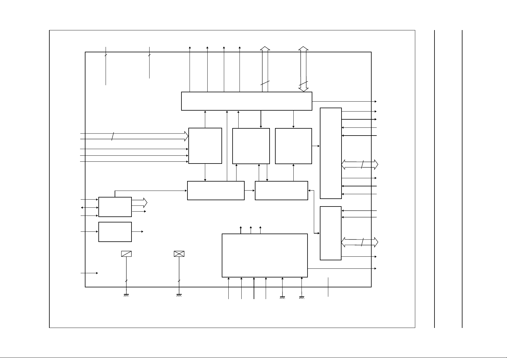
5 BLOCK DIAGRAM
Encoder for MPEG2 image recording
(EMPIRE)
SAA6750H
Philips Semiconductors Preliminary specification
V
SS
V
SSCO
CS_TEST n.c.
TESTTMS TDITRST TCK
Fig.1 Block diagram.

Philips Semiconductors Preliminary specification
Encoder for MPEG2 image recording
(EMPIRE)
6 PINNING
I
max
SYMBOL PIN INPUT/OUTPUT
V
SS
1 ground − ground for pad ring
DATA28 2 input/output 3 DRAM data interface bit 28
DATA29 3 input/output 3 DRAM data interface bit 29
DATA30 4 input/output 3 DRAM data interface bit 30
DATA31 5 input/output 3 DRAM data interface bit 31
V
DD
6 supply − supply voltage for pad ring
DATA32 7 input/output 3 DRAM data interface bit 32
DATA33 8 input/output 3 DRAM data interface bit 33
DATA34 9 input/output 3 DRAM data interface bit 34
DATA35 10 input/output 3 DRAM data interface bit 35
V
SS
11 ground − ground for pad ring
DATA36 12 input/output 3 DRAM data interface bit 36
DATA37 13 input/output 3 DRAM data interface bit 37
DATA38 14 input/output 3 DRAM data interface bit 38
DATA39 15 input/output 3 DRAM data interface bit 39
V
DD
16 supply − supply voltage for pad ring
DATA40 17 input/output 3 DRAM data interface bit 40
DATA41 18 input/output 3 DRAM data interface bit 41
DATA42 19 input/output 3 DRAM data interface bit 42
DATA43 20 input/output 3 DRAM data interface bit 43
V
SS
V
DDCO
V
SSCO
V
DDCO
V
SSCO
V
DDCO
V
SSCO
V
DD
21 ground − ground for pad ring
22 supply − supply voltage for core logic
23 ground − ground for core logic
24 supply − supply voltage for core logic
25 ground − ground for core logic
26 supply − supply voltage for core logic
27 ground − ground for core logic
28 supply − supply voltage for pad ring
DATA44 29 input/output 3 DRAM data interface bit 44
DATA45 30 input/output 3 DRAM data interface bit 45
DATA46 31 input/output 3 DRAM data interface bit 46
DATA47 32 input/output 3 DRAM data interface bit 47
V
SS
33 ground − ground for pad ring
DATA48 34 input/output 3 DRAM data interface bit 48
DATA49 35 input/output 3 DRAM data interface bit 49
DATA50 36 input/output 3 DRAM data interface bit 50
DATA51 37 input/output 3 DRAM data interface bit 51
V
DD
38 supply − supply voltage for pad ring
DATA52 39 input/output 3 DRAM data interface bit 52
(1)
(mA)
SAA6750H
DESCRIPTION
1998 Sep 07 7

Philips Semiconductors Preliminary specification
Encoder for MPEG2 image recording
(EMPIRE)
I
max
SYMBOL PIN INPUT/OUTPUT
DATA53 40 input/output 3 DRAM data interface bit 53
DATA54 41 input/output 3 DRAM data interface bit 54
DATA55 42 input/output 3 DRAM data interface bit 55
V
SS
43 ground − ground for pad ring
DATA56 44 input/output 3 DRAM data interface bit 56
DATA57 45 input/output 3 DRAM data interface bit 57
DATA58 46 input/output 3 DRAM data interface bit 58
DATA59 47 input/output 3 DRAM data interface bit 59
V
DD
48 supply − supply voltage for pad ring
DATA60 49 input/output 3 DRAM data interface bit 60
DATA61 50 input/output 3 DRAM data interface bit 61
DATA62 51 input/output 3 DRAM data interface bit 62
DATA63 52 input/output 3 DRAM data interface bit 63 (MSB)
V
SS
53 ground − ground for pad ring
ADR0 54 output/3-state 3 DRAM address interface bit 0 (LSB)
ADR1 55 output/3-state 3 DRAM address interface bit 1
ADR2 56 output/3-state 3 DRAM address interface bit 2
ADR3 57 output/3-state 3 DRAM address interface bit 3
V
DD
58 supply − supply voltage for pad ring
ADR4 59 output/3-state 3 DRAM address interface bit 4
ADR5 60 output/3-state 3 DRAM address interface bit 5
ADR6 61 output/3-state 3 DRAM address interface bit 6
ADR7 62 output/3-state 3 DRAM address interface bit 7
V
SS
63 ground − ground for pad ring
ADR8 64 output/3-state 3 DRAM address interface bit 8 (MSB)
CASN 65 output/3-state 6 DRAM column address strobe (active LOW)
V
DD
66 supply − supply voltage for pad ring
RASN 67 output/3-state 3 DRAM row address strobe (active LOW)
WEN 68 output/3-state 3 DRAM write enable (active LOW)
OEN 69 output/3-state 3 DRAM chip select (active LOW)
V
SS
70 ground − ground for pad ring
YUV0 71 input − video input signal bit 0 (LSB)
YUV1 72 input − video input signal bit 1
YUV2 73 input − video input signal bit 2
YUV3 74 input − video input signal bit 3
V
SSCO
V
DDCO
V
SSCO
V
DDCO
V
SSCO
75 ground − ground for core logic
76 supply − supply voltage for core logic
77 ground − ground for core logic
78 supply − supply voltage for core logic
79 ground − ground for core logic
(1)
(mA)
DESCRIPTION
SAA6750H
1998 Sep 07 8

Philips Semiconductors Preliminary specification
Encoder for MPEG2 image recording
(EMPIRE)
I
max
SYMBOL PIN INPUT/OUTPUT
V
DDCO
V
SSCO
V
DDCO
V
SSCO
80 supply − supply voltage for core logic
81 ground − ground for core logic
82 supply − supply voltage for core logic
83 ground − ground for core logic
YUV4 84 input − video input signal bit 4
YUV5 85 input − video input signal bit 5
YUV6 86 input − video input signal bit 6
YUV7 87 input − video input signal bit 7 (MSB)
V
DD
88 supply − supply voltage for pad ring
FID 89 input − odd/even field identification
HSYNC 90 input − horizontal reference signal
VSYNC 91 input − vertical reference signal
V
SS
92 ground − ground for pad ring
VCLK 93 input − video clock input (27 MHz)
V
DD
V
SS
94 supply − supply voltage for pad ring
95 ground − ground for pad ring
RESETN 96 input − hard reset input (active LOW)
MAD 97 input − module address (I2C-bus)
SDA 98 input/open drain output 6 serial data input/output (I
SCL 99 input/open drain output − serial clock input (I
V
DD
100 supply − supply voltage for pad ring
MEM_ST 101 output/3-state 3 do not use in the application (reserved)
FAD_RWN 102 input − ASIP port data read/
FAD_EN 103 input − ASIP port data enable
FAD_RDYN 104 open drain output 3 ASIP port data ready (active LOW)
V
SS
105 ground − ground for pad ring
GPIO0 106 input/output 3 ASIP port data bit 0 (LSB)
GPIO1 107 input/output 3 ASIP port data bit 1
GPIO2 108 input/output 3 ASIP port data bit 2
GPIO3 109 input/output 3 ASIP port data bit 3
V
DD
110 supply − supply voltage for pad ring
GPIO4 111 input/output 3 ASIP port data bit 4
GPIO5 112 input/output 3 ASIP port data bit 5
GPIO6 113 input/output 3 ASIP port data bit 6
GPIO7 114 input/output 3 ASIP port data bit 7
V
SS
115 ground − ground for pad ring
GPIO8 116 input/output 3 ASIP port data bit 8
GPIO9 117 input/output 3 ASIP port data bit 9
GPIO10 118 input/output 3 ASIP port data bit 10
GPIO11 119 input/output 3 ASIP port data bit 11 (MSB)
(1)
(mA)
DESCRIPTION
2
C-bus)
2
C-bus)
write
SAA6750H
1998 Sep 07 9

Philips Semiconductors Preliminary specification
Encoder for MPEG2 image recording
SAA6750H
(EMPIRE)
I
max
SYMBOL PIN INPUT/OUTPUT
V
DD
120 supply − supply voltage for pad ring
(1)
(mA)
LRQN 121 open drain output 3 output port lower watermark interrupt request (active LOW)
URQN 122 open drain/3-state 3 output port upper watermark interrupt request (active LOW)
DTACK_RDY 123 open drain output 3 output port data transfer acknowledge/ready/request
I_MN 124 input − output port Intel/Motorola bus style selection input
(active LOW); with internal pull-up resistor
CSN 125 input − output port chip select for external address mode (active LOW);
with internal pull-up resistor
V
DDCO
V
SSCO
V
DDCO
V
SSCO
V
DDCO
V
SSCO
V
DDCO
V
SSCO
V
DDCO
126 supply − supply voltage for core logic
127 ground − ground for core logic
128 supply − supply voltage for core logic
129 ground − ground for core logic
130 supply − supply voltage for core logic
131 ground − ground for core logic
132 supply − supply voltage for core logic
133 ground − ground for core logic
134 supply − supply voltage for core logic
AS_ALE 135 input − output port address strobe/address latch enable
DS_RDN 136 input − output port data strobe/read
V
SS
137 ground − ground for pad ring
AD15 138 input/output 3 output port multiplexed address/data line bit 15 (MSB)
AD14 139 input/output 3 output port multiplexed address/data line bit 14
AD13 140 input/output 3 output port multiplexed address/data line bit 13
AD12 141 input/output 3 output port multiplexed address/data line bit 12
V
DD
142 supply − supply voltage for pad ring
AD11 143 input/output 3 output port multiplexed address/data line bit 11
AD10 144 input/output 3 output port multiplexed address/data line bit 10
AD9 145 input/output 3 output port multiplexed address/data line bit 9
AD8 146 input/output 3 output port multiplexed address/data line bit 8
V
SS
147 ground − ground for pad ring
AD7 148 input/output 3 output port multiplexed address/data line bit 7/data bus bit 7
(MSB)
AD6 149 input/output 3 output port multiplexed address/data line bit 6/data bus bit 6
AD5 150 input/output 3 output port multiplexed address/data line bit 5/data bus bit 5
AD4 151 input/output 3 output port multiplexed address/data line bit 4/data bus bit 4
V
DD
152 supply − supply voltage for pad ring
AD3 153 input/output 3 output port multiplexed address/data line bit 3/data bus bit 3
AD2 154 input/output 3 output port multiplexed address/data line bit 2/data bus bit 2
AD1 155 input/output 3 output port multiplexed address/data line bit 1/data bus bit 1
AD0 156 input/output 3 output port multiplexed address/data line bit 0 (LSB)/data bus
bit 0 (LSB)
DESCRIPTION
1998 Sep 07 10

Philips Semiconductors Preliminary specification
Encoder for MPEG2 image recording
SAA6750H
(EMPIRE)
I
max
SYMBOL PIN INPUT/OUTPUT
V
SS
157 ground − ground for pad ring
TDO 158 output 3 boundary scan test data output; pin not active during normal
TRST 159 input − boundary scan test reset; pin must be set to LOW for normal
TCK 160 input − boundary scan test clock; pin must be set to LOW during normal
TMS 161 input − boundary scan test mode select; pin must float or set to HIGH
V
DDCO
162 supply − supply voltage for core logic
TDI 163 input − boundary scan test data input; pin must float or set to HIGH
CS_TEST 164 input − test mode for the internal RAMs; pin must be set to LOW during
TEST 165 input − test mode; pin must be set to LOW during normal operation
V
DD
166 supply − supply voltage for pad ring
DATA0 167 input/output 3 DRAM data interface bit 0 (LSB)
DATA1 168 input/output 3 DRAM data interface bit 1
DATA2 169 input/output 3 DRAM data interface bit 2
DATA3 170 input/output 3 DRAM data interface bit 3
V
SS
171 ground − ground for pad ring
DATA4 172 input/output 3 DRAM data interface bit 4
DATA5 173 input/output 3 DRAM data interface bit 5
DATA6 174 input/output 3 DRAM data interface bit 6
DATA7 175 input/output 3 DRAM data interface bit 7
V
DD
V
SSCO
V
DDCO
V
SSCO
V
DDCO
V
SSCO
V
DDCO
V
SSCO
176 supply − supply voltage for pad ring
177 ground − ground for core logic
178 supply − supply voltage for core logic
179 ground − ground for core logic
180 supply − supply voltage for core logic
181 ground − ground for core logic
182 supply − supply voltage for core logic
183 ground − ground for core logic
n.c. 184 −−reserved pin; do not connect
DATA8 185 input/output 3 DRAM data interface bit 8
DATA9 186 input/output 3 DRAM data interface bit 9
DATA10 187 input/output 3 DRAM data interface bit 10
DATA11 188 input/output 3 DRAM data interface bit 11
V
SS
189 ground − ground for pad ring
DATA12 190 input/output 3 DRAM data interface bit 12
DATA13 191 input/output 3 DRAM data interface bit 13
(1)
(mA)
DESCRIPTION
operation; with 3-state output; note 2
operation; with internal pull-up resistor; notes 2 and 3
operation; with internal pull-up resistor; note 2
during normal operation; with internal pull-up resistor; note 2
during normal operation; with internal pull-up resistor; note 2
normal operation
1998 Sep 07 11

Philips Semiconductors Preliminary specification
Encoder for MPEG2 image recording
(EMPIRE)
I
max
SYMBOL PIN INPUT/OUTPUT
DATA14 192 input/output 3 DRAM data interface bit 14
DATA15 193 input/output 3 DRAM data interface bit 15
V
DD
DATA16 195 input/output 3 DRAM data interface bit 16
DATA17 196 input/output 3 DRAM data interface bit 17
DATA18 197 input/output 3 DRAM data interface bit 18
DATA19 198 input/output 3 DRAM data interface bit 19
V
SS
DATA20 200 input/output 3 DRAM data interface bit 20
DATA21 201 input/output 3 DRAM data interface bit 21
DATA22 202 input/output 3 DRAM data interface bit 22
DATA23 203 input/output 3 DRAM data interface bit 23
V
DD
DATA24 205 input/output 3 DRAM data interface bit 24
DATA25 206 input/output 3 DRAM data interface bit 25
DATA26 207 input/output 3 DRAM data interface bit 26
DATA27 208 input/output 3 DRAM data interface bit 27
194 supply − supply voltage for pad ring
199 ground − ground for pad ring
204 supply − supply voltage for pad ring
(1)
(mA)
DESCRIPTION
SAA6750H
Notes
1. All input, I/O (in input mode), output (in 3-state mode) and open drain output pins are 5.0 V tolerant.
2. In accordance with the
3. Special functionality of pin TRST:
a) For board designs without boundary scan implementation, pin TRST must be connected to ground.
b) Pin TRST provides easy initialization of the internal BST circuit. By applying a LOW it can be used to force the
internal Test Access Port (TAP) controller to the Test-Logic-Reset state (normal operation) at once.
The 208 pins are divided in following groups:
Video input port (11 pins):
8 data pins
3 control pins.
Data output port (23 pins):
16 data pins
7 control pins.
GPIO port (15 pins):
12 data pins
3 control pins.
DRAM (77 pins):
64 data pins
9 address pins
4 control pins.
“IEEE 1149.1”
standard.
Others (14 pins):
1 video clock input pin
3 pins related to the I2C-bus
1 pin for reset control
7 pins for test purposes
1 pin not connected
1 pin for internal test purposes.
Supply (68 pins):
16 core supply pins
18 I/O cell supply pins
16 core ground pins
18 I/O cell ground pins.
1998 Sep 07 12

Philips Semiconductors Preliminary specification
Encoder for MPEG2 image recording
(EMPIRE)
handbook, halfpage
52
208
1
SAA6750H
53
157
104
SAA6750H
156
105
MBK768
Fig.2 Pin configuration.
7 FUNCTIONAL DESCRIPTION
7.1 Global architecture description
7.1.1 G
ENERAL
The SAA6750H has a multi-processor architecture.
The different processing and control modules are not
locked to each other but run independently within the limits
of the global scheduling. The data transfer between the
processing units is carried out via FIFO memories or the
external DRAM (see Fig.1).
The set of functions of the SAA6750H is to a high extent
determined by the microcode of the internal Application
Specific Instruction-set Processor (ASIP). Detailed
information is given in the software specification.
Global settings and selection of the operation modes are
carried out via I2C-bus (see Sections 7.2 and 7.9).
7.1.2 A
RCHITECTURE STRUCTURE
The architecture consist of a data processing, a control
and a memory part.
7.1.2.1 Data processing part
Line based processing:
Video front-end and formatter (see Section 7.3) including:
1. 4:2:2to4:2:0 pre-filter
2. Optional SIF subsampling.
The video front-end processes the incoming video data
and writes it to the external DRAM.
Macroblock based processing:
MacroBlock Processor (MBP) (see Section 7.4) including:
1. Discrete Cosine Transformation/Inverse Discrete
Cosine Transformation (DCT/IDCT)
2. Variable Length Encoding/Run Length Encoding
(VLE/RLE)
3. Motion Estimation/Motion Compensation (ME/MC)
4. Motion Compensation Noise Reduction (MCNR)
5. Quantization/Inverse Quantization (Q/IQ)
6. Frame/Field reshuffling and zigzag scan (FF, ZZ).
The MBP gets the pre-processed video data from the
external DRAM and performs the data compression.
The data processing flow can be split-up as follows:
1998 Sep 07 13

Philips Semiconductors Preliminary specification
Encoder for MPEG2 image recording
(EMPIRE)
Bit-stream based processing:
Bit stream assembly (see Section 7.5) including:
1. Pre-packer
2. Packer
3. Stuffing unit and output buffer.
Data output port (see Section 7.6).
The bit-stream processing part gets the compressed data
from the MBP and the header information from the control
part. It provides an MPEG2 compliant elementary stream
at the output.
7.1.2.2 Control part
The control part consists of three modules:
1. Application Specific Instruction-set Processor (ASIP)
(see Section 7.7); controls the MBP, generates motion
vectors, headers and stuffing information.
2. The global controller (see Section 7.8); generates the
global scheduling information for the MBP, the DRAM
interface and the ASIP.
3. The I2C-bus interface and controller (see Section 7.9);
download of ASIP microcode, tables and constants as
well as MBP quantizer table, used for external control
settings, allows communication between ASIP and
application environment.
7.1.2.3 Memory part
The control and data processing modules exchange data
via internal FIFOs and the external DRAM:
1. DRAM interface (see Section 7.10); provides access
to the external DRAM memory.
2. FIFO memories (see Section 7.11); a number of
FIFOs of different size is used to connect internal
processing units.
7.2 Start-up and operation modes
7.2.1 S
Simultaneously with power-on, the SAA6750H requires a
LOW level at pin RESETN. This external reset has to be
kept active until the external video clock signal VCLK has
been running stable within the specified limits for at least
10 clock cycles (see Chapter “Quick reference data”).
A suitable combination of RESETN and clock signal is e.g.
provided by Philips product family SAA7111A. For proper
reset behaviour and operation pin TRST has to be LOW.
TART-UP REQUIREMENTS
SAA6750H
After power on and the related internal reset the
initialization via I
(see Section 7.9.5). It should be noted that a delay of at
least 0.5 ms between the end of RESETN LOW state and
start of the I2C-bus initialization sequence is required.
See Table 1 for information about the operation modes.
7.2.2 R
The SAA6750H has internally an asynchronous and a
synchronous reset processing.
The asynchronous reset is directly derived from the
external reset signal RESETN and gets active as soon as
RESETN becomes LOW. It is not depending on the
external clock signal. The asynchronous reset forces the
SAA6750H into reset mode which does directly affect the
behaviour of the output and I/O pins (see Table 2).
This does guarantee a defined state of the pins even if no
clock signal is available. In addition it initiates the internal
synchronous reset which gets active as soon as the VCLK
signal is available.
The internal synchronous reset is controlled by RESETN
and the settings of control bits E_ST and E_SP.
For proper operation the external clock signal VCLK has to
be stable within the specified limits.
The internal synchronous reset gets active if RESETN is
LOW or by setting the control bits E_ST and E_SP to soft
reset mode (see Table 1). It does affect all internal
modules except the I
the output and I/O pins (see Table 2). In addition, but only
if combined with an external reset RESETN, it does reset
the I2C-bus control register. It does not affect the contents
of the embedded microcode and constant memories
(see Section 7.9.4).
See Table 2 for detailed information about the impact of
external and internal reset signals as well as control bit
settings on the behaviour of internal modules and output
pins.
After release of the external reset or setting back E_ST
and E_SP to operation mode, the internal synchronous
reset remains active for 7562 clock cycles (approximately
260 µs). During this time the DRAM initialization sequence
is carried out (see Section 7.10.3.2). All other internal
modules except the I2C-bus control register stay in reset
mode for this time. The external DRAM will not be
refreshed during internal synchronous reset.
2
C-bus has to be carried out
ESET PROCESSING
2
C-bus controller and therefore also
1998 Sep 07 14

Philips Semiconductors Preliminary specification
Encoder for MPEG2 image recording
SAA6750H
(EMPIRE)
7.2.3 DESCRIPTION OF OPERATION MODES
Depending on the reset processing and the setting of
I2C-bus control bits E_ST and E_SP (see Tables 24
and 25) the SAA6750H can be set to different operation
modes. Purpose and behaviour are described in Table 1.
After an external reset pulse at RESETN, the init mode will
be active because control bits E_ST and E_SP are set to
LOW.
7.2.4 P
The behaviour of I/O and output pins is depending on the
operation mode of the SAA6750H. In reset mode the pins
Table 1 SAA6750H operation modes
OPERATION
Reset mode 0 X X In reset mode all I/O and output pins are forced to a defined state with
Init mode 1 0 0 In init mode the device initialization via I
Soft reset mode 1 0 1 Activates the internal synchronous reset. All internal modules except the
Operation mode 1 1 0 Normal operation.
IN BEHAVIOUR
ACTIVATED BY
MODE
− 1 1 1 Internal use only.
RESETN E_ST E_SP
RESETN = LOW (refer to Table 2). After VCLK is available, also the
internal reset becomes active, which puts the internal modules in reset
state. The I
RESETN back to HIGH, the internal reset will remain active for 7562
clock cycles. The DRAM initialization sequence will run during this time
(see Section 7.10.3.2).
The external DRAM is not refreshed. See Table 2 for behaviour of pins
during init mode. This mode will be active after external reset due to reset
of E_ST and E_SP.
Remark: Do not switch from operation mode to init mode directly. Always
use the soft reset or reset mode as intermediate step.
2
I
C-bus control register are in reset mode. This mode allows e.g.
operation of a second device SAA6750H. Therefore output and I/O pins
are in input or 3-state mode (see T able2). The external DRAM will not be
refreshed. After setting E_SP back to LOW, the internal reset will remain
active for 7562 clock cycles. The DRAM initialization sequence will run
during this time (see Section 7.10.3.2).
are forced to a certain behaviour even if no clock VCLK is
available. Reset mode overrules all other internal pin
settings. During soft reset mode all output and I/O pins that
could create driver conflicts with other devices are forced
to 3-state or input mode. The internal reset is active during
a period of 7562 clock cycles after reset mode and soft
reset mode. The status of pins is determined by the reset
behaviour of the internal modules. The internal reset
behaviour applies also for the init mode because init mode
always follows internal reset.
In operation mode the status of the pins is depending on
the function of the SAA6750H.
DESCRIPTION
2
C-bus control register is cleared in this mode. After setting
2
C-bus has to be performed.
1998 Sep 07 15

Philips Semiconductors Preliminary specification
Encoder for MPEG2 image recording
SAA6750H
(EMPIRE)
Table 2 Behaviour of output and I/O pins
PIN STATUS
PIN NAME DESCRIPTION
DATA0 to DATA63 DRAM data input/output input input input
ADR0 to ADR8 DRAM address output 3-state output 3-state
CASN DRAM column address strobe output 3-state output 3-state
RASN DRAM row address strobe output 3-state output 3-state
WEN DRAM write enable output 3-state output 3-state
OEN DRAM chip select output 3-state output 3-state
SDA I
SCL I
MEM_ST reserved output 3-state output 3-state
FAD_RDYN ASIP data port; data ready output open drain;
GPIO0 to GPIO11 ASIP data port; input/output input input input
LRQN output port lower watermark interrupt
URQN output port upper watermark interrupt
DTACK_RDY output port data transfer
AD0 to AD15 output port address/data input/output input input input
2
C-bus data input/open drain output input normal operation normal operation
2
C-bus clock input/output input normal operation normal operation
request
request
acknowledge/ready/request
RESET MODE
note 1
open drain on open drain
open drain on open drain
open drain on open drain
INIT MODE &
INTERNAL RESET
open drain open drain
SOFT RESET
MODE
Note
1. Only defined if external clock is available.
7.3 Video front-end and formatter
7.3.1 G
The video front-end and formatter module consists of an
8-bit data input interface, a formatter sub-module and a
luminance and a chrominance address processing unit.
The interface is designed for use with Philips SAA7111
video decoder family or similar foreign products. The input
interface accepts a digital video input stream according to
“ITU-T 601”
576 lines as well as NTSC at 60 Hz and 720 pixel by
480 lines are covered.The video synchronization may
either follow
supplied by external signals (HSYNC, VSYNC and FID).
The formatter module performs a colour conversion from
4:2:2to4:2:0 format. Optionally, also an SIF
down-scaling may be activated for PAL as well as NTSC
standard signals. The luminance and chrominance
processing units do generate the addresses for storing the
front-end output data in the external DRAM memory.
ENERAL
. PAL standard at 50 Hz and 720 pixel by
“ITU-T 656”
recommendation or can also be
7.3.2 D
The 8-bit video input data has to be transferred at a
frequency of 27 Mwords/s (13.5 MHz for luminance and
6.25 MHz for both chrominance components) i.e. one data
word per clock cycle has to be sent. The elements of a
data stream have the following order: CB, Y, CR, Y, CB, Y,
CR, Y, etc. The byte combinations 00H and FFH are
reserved for synchronization purposes, so that only a
subset of 254 of all possible 28= 256 combinations are
used. See Section 7.3.3 for detailed information about the
synchronization signals.
The external reference clock VCLK has to be
synchronized to the video input data.
ATA INPUT FORMAT
1998 Sep 07 16

Philips Semiconductors Preliminary specification
Encoder for MPEG2 image recording
SAA6750H
(EMPIRE)
7.3.3 FUNCTIONAL DESCRIPTION
7.3.3.1 General
The video front-end and formatter module consists of four
submodules:
1. The 8-bit data interface and the related control signals
connect the SAA6750H to external data sources like
e.g. Philips SAA711x product family.
2. The formatter submodule covers two main functions:
The processing of the synchronization information
(sync processing) and the processing of the picture
contents (line based processing).
3. The luminance and chrominance submodules
generate the addresses in the external DRAM memory
where the output data of the video front-end and
formatter module is stored.
Table 3 Video front-end and formatter mode selection
CONTROL BITS
STD SS SMOD
0 0 X NTSC NTSC input signal processing (60 Hz and 720 pixel by 480 lines).
1 0 X PAL PAL input signal processing (50 Hz and 720 pixel by 576 lines).
0 1 X NTSC-SIF NTSC input signal processing (60 Hz and 720 pixel by 480 lines).
1 1 X PAL-SIF PAL input signal processing (50 Hz and 720 pixel by 576 lines).
X X 0 ITU-T 656 ITU-T 656 mode sync processing mode. Sync information is
X X 1 external sync External sync processing mode. Sync information is provided via
(1)
MODE FUNCTION
SIF down-scaling active.
SIF down-scaling active.
embedded in the video data input stream.
pins FID, HSYNC and VSYNC.
The video front-end and formatter module offers various
operation modes. The appropriate setting can be selected
2
in the I
It should be noted that changes of video standard or
synchronization settings are only allowed in init mode or
soft reset mode. See Section 7.2.3 for information of the
operation modes.
C-bus control register (see Tables 1 and 24).
Note
1. Changes of video standard or synchronization setup settings are only allowed in init mode or soft reset mode.
X = don’t care. See Section 7.2.3 for information of the SAA6750H operation modes.
1998 Sep 07 17

Philips Semiconductors Preliminary specification
Encoder for MPEG2 image recording
SAA6750H
(EMPIRE)
7.3.3.2 Interface definition
The data input interface uses in total 11 pins. Pins YUV0 to YUV7 carry video and synchronization data. 3 pins are
reserved for control purposes (see Table 4).
Table 4 List of pins data input port
PIN NAME PIN TYPE DESCRIPTION
YUV0 to YUV7 input video input signal (synchronous to VCLK)
FID input odd/even field identification signal; note 1
HSYNC input horizontal synchronization signal; note 1
VSYNC input vertical synchronization signal; note 1
Note
1. In ITU-T 656 mode sync signals are embedded in the video data input stream. The external sync signals are not
used.
7.3.3.3 Line based processing
The line based processing works the same way for PAL and NTSC signals.
Each of the three components of the video signals Y, U and V, are filtered horizontally. The filter is symmetrical and has
seven taps. The seven taps are weighted with three programmable parameters a1, a2 and a3 as shown in Table 5.
Table 5 Horizontal filtering
TAP −3 −2 −1 0 123
Horizontal filtering f(a1, a2, a3) a3 a2 a1 1 − 2(a1 + a2 + a3) a1 a2 a3
The three parameters must be loaded by setting the I
0 to 255. Reset state is 0.
To convert the video signal from 4 : 2 : 2 to 4:2:0 format, vertical filtering and subsampling of the chrominance
components has to be performed. The vertical filter has six taps. The filter coefficients are given in Table 6.
Table 6 Vertical filtering
TAP 123456
Vertical filtering top fields −3133024 4 −4
Vertical filtering bottom fields −4 4 24 30 13 −3
As mentioned, optionally an SIF mode conversion of PAL or NTSC standard input signals may be activated by setting
2
the I
C-bus control bit SS (see Tables 1 and 24). To convert the video signal to SIF resolution the bottom fields are
discarded. Furthermore, all components of the video signal are horizontally subsampled by factor two.
2
C-bus control register words A1, A2 and A3. The valid range is
1998 Sep 07 18

Philips Semiconductors Preliminary specification
Encoder for MPEG2 image recording
(EMPIRE)
7.3.3.4 Sync processing
Because the synchronization information may be delivered
by a video data source in two different ways, the internal
sync processing of the SAA6750H is carried out in two
related modes:
1. The ITU-T 656 mode.
The ITU-T 656 recommendation describes the
unidirectional interconnection between a video data
source and a video data sink. Luminance and
chrominance data as well as the complete set of
control data (V-sync, H-sync, field indication or byte
information like SAV, EAV, etc.) are transferred
interleaved on one 8-bit bus. Both, sync and data
signal, are in the form of binary coded 8-bit words.
The external sync signals HSYNC, VSYNC and FID
are not used.
2. The external sync mode.
The synchronization may also be provided via
pins HSYNC, VSYNC and FID. In this case, the
8-bit bus carries only the video data information.
The internal sync processing mode may be selected by the
2
C-bus control bit SMOD (see Tables 1 and 24).
I
Sync signals must be active at regular time intervals. If a
time interval is too short, a sync is skipped. Top and
bottom fields must follow each other. If two top fields or two
bottom fields follow each other immediately, than the
second field is skipped.
The number of clock cycles and H-sync signals that have
to occur before processing starts (horizontal and vertical
shift) can be set via I2C-bus. In this way the active part of
the video can be determined. The vertical shift can be
specified independently for top and bottom fields by using
the control words VERTICAL SHIFT TOP FIELD
and VERTICAL SHIFT BOTTOM FIELD (see Table 24).
The horizontal shift is controlled by control word
HORIZONTAL SHIFT. The shift can be programmed in a
range of 127 clock cycles in horizontal direction
respectively 127 lines in vertical direction. Horizontal shift
should be carried out in steps of a multiple of 4 because a
minimum data sequence (CB, Y, CR, Y) needs 4 clock
cycles. It should be noted that the horizontal blanking in
PAL mode takes 280 clock cycles and in NTSC mode
268 cycles.
SAA6750H
Internally, the edge-detection circuitries for these signals
change polarity with these settings. By this way different
synchronization schemes are supported. The horizontal
respectively vertical processing starts with the selected
edge.
Due to requirements from the internal vertical filtering the
line based processing needs 3 horizontal sync pulses
during vertical blanking which have to follow directly the
active part of the frame (e.g. 288 active lines in
PAL mode). The related line data is not processed.
This restriction does not allow edge selection at the end of
the previous field [e.g. vertical sync of line 623 or line 1
(see Fig.3)]. In this case the polarity bit VREFP has to be
set, to select the falling edge of the sync lines.
The Sections 7.3.3.5, 7.3.3.6 and 7.3.3.7 as well as the
related Section 7.3.3.8 contain descriptions of different
styles of synchronization signals and how they are
handled in the SAA6750H.
7.3.3.5 Sync processing PAL (50 Hz)
The PAL (50 Hz) input signal has 625 lines per frame and
typically takes 1728 clock cycles per line. The minimum
number of clock cycles per line is 1706. The active part of
a field consists of 288 lines of 720 pixels (see Fig.7).
Figures 3 and 4 and the related Table 7 give an example
illustrating how different sources providing different
external sync signals can be adapted to the SAA6750H.
In the given example, the SAA711x is connected to
pins HSYNC, VSYNC and FID and provides external sync
signals in two different modes: according to the timing
convention of the ITU-T 656 mode and in a SAA711x
proprietary format. In addition, another mode,
HREF/VREF, is mentioned in Table 7. From timing point of
view the HREF/VREF mode behaves like ITU-T 656, but
signals horizontal sync and vertical sync (VSYNC) are
inverted. See data sheet SAA7111A for detailed
information.
As mentioned, in addition to the external sync mode, the
ITU-T 656 mode is supported. Sections 7.3.3.7, 7.3.3.8
and Figs 7 and 8 contain detailed information on this sync
mode.
Due to the fact that the horizontal offset value can not
compensate the whole blanking interval, the polarity of the
three external sync lines (H-SYNC, V-SYNC and FID) can
also be adapted via I2C-bus. Control bits HREFP, VREFP
and FIDP are used for this purpose (see Table 24).
1998 Sep 07 19

Philips Semiconductors Preliminary specification
Encoder for MPEG2 image recording
(EMPIRE)
FID (ITU-T656 timing)
VSYNC (ITU-T656 timing)
FID (SAA711x proprietary timing)
VSYNC (SAA711x proprietary timing)
(1)
621
(308)
(2)
(309) (310) (311) (312) (1) (2) (3) (4) (5) (6) (7) (8)
625 1 2 3 4 5 6 7 8624623622
SAA6750H
(1) The line numbers not in parenthesis refer to ITU-T counting.
(2) The line numbers in parenthesis refer to single field counting.
Fig.3 External sync timing of SAA711x, 50 Hz, lines 621 to 8.
FID (ITU-T656 timing)
VSYNC (ITU-T656 timing)
FID (SAA711x proprietary timing)
VSYNC (SAA711x proprietary timing)
(1)
308
(2)
(309) (310) (311) (312) (313) (1) (2) (3) (4) (5) (6) (7) (8)(308)
312 313 314 315 316 317 318 319 320 321311310309
(1) The line numbers not in parenthesis refer to ITU-T counting.
(2) The line numbers in parenthesis refer to single field counting.
Fig.4 External sync timing of SAA711x, 50 Hz, lines 308 to 321.
1998 Sep 07 20
 Loading...