

Philips saa5261, saa5262, saa5263 DATASHEETS

INTEGRATED CIRCUITS
DATA SH EET
SAA5261; SAA5262; SAA5263
10-page intelligent teletext
decoders
Product specification
File under Integrated Circuits, IC02
1998 Apr 22

Philips Semiconductors Product specification
10-page intelligent teletext decoders SAA5261; SAA5262; SAA5263
FEATURES
SAA5261, SAA5262 and SAA5263
• Complete 625-line teletext decoder in a single
integrated circuit thereby reducing printed-circuit board
area and cost
• Automatic detection of transmitted pages so that only
existing pages will be selected by page-up and
page-down once inventory validated
• Automatic detection of transmitted Fastext links or
service information (packet 8/30)
• On-screen display for user interface (menus, etc.) using
teletext and dedicated menu icons
• Video Programming System (VPS) decoding
• Wide Screen Signalling (WSS) decoding
• 8-page Fastext decoder
• 6-page TOP decoder in addition to capture ofBasic TOP
Table (BTT) and 3 Additional Information Table (AIT)
pages
• 4-page user defined list mode
• Yugoslavian, Cyrillic, Greek/Turkish, Thai,
Arabic/Hebrew, Pan-European and
Arabic/English/French language coverage
• High level command interface via I
control from a low software overhead
• High level command interface is backward compatible to
SAFARI interface
• 625 and 525 line display
• RGB interface to standard colour decoder ICs, push-pull
output drive
• Versatile 8-bit open-drain I/O expander
• Single 12 MHz crystal oscillator for reduced cost
• +5 V power supply.
2
C-bus giving easy
SAA5262 and SAA5263
• Automatic Channel Installation (ACI)
• Enhanced SAFARI interface providing additional
commands.
SAA5263
• Electronic Programme Guide (EPG) feature.
GENERAL DESCRIPTION
The SAA526xPS ICs are single-chip 10-page 625-line
World System Teletext (WST) decoders with a high level
command interface, SAFARI compatible.
It has been designed so that the overall system cost is kept
to a minimum. This has been achieved through the
capability of the device to be driven from a single +5 V
power supply, low cost 12 MHz crystal oscillator and the
high level command interface, which offers the benefit of
low software overhead in the TV microcontroller.
The SAA526xPS offers automatic detection of Fastext or
TOP transmissions. The device also incorporates a facility
to detect the pages in the transmission, which allows only
transmitted pages to be selected by page-up and
page-down.
SAA5262 and SAA5263 provide Automatic Channel
Installation (ACI) information.
SAA5263 provides access to Electronic Programme Guide
(EPG) information.
1998 Apr 22 2

Philips Semiconductors Product specification
10-page intelligent teletext decoders SAA5261; SAA5262; SAA5263
ORDERING INFORMATION
TYPE NUMBER
PACKAGE
NAME DESCRIPTION VERSION
SAA5261PS SDIP52 plastic shrink dual in-line package; 52 leads (600 mil) SOT247-1
SAA5262PS SDIP52 plastic shrink dual in-line package; 52 leads (600 mil) SOT247-1
SAA5263PS SDIP52 plastic shrink dual in-line package; 52 leads (600 mil) SOT247-1
QUICK REFERENCE DATA
SYMBOL PARAMETER MIN. TYP. MAX. UNIT
V
DDD
I
DDD(M)
I
DDA
I
DDD(T)
f
xtal
T
amb
digital supply voltage 4.5 5.0 5.5 V
microcontroller supply current − 20 35 mA
analog supply current − 35 50 mA
teletext supply current − 50 80 mA
crystal frequency − 12 − MHz
operating ambient temperature −20 − +70 °C
1998 Apr 22 3
Philips Semiconductors Product specification
10-page intelligent teletext decoders SAA5261; SAA5262; SAA5263
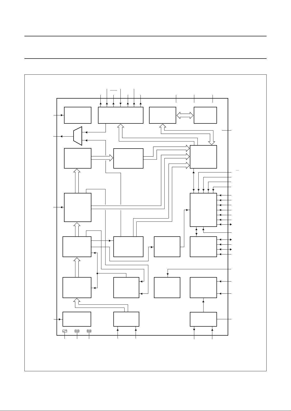
BLOCK DIAGRAM
handbook, full pagewidth
RESET
FRAME
PL
43
POWER-ON
27
21
ACQUISITION
SERIAL-TO-
CONVERTER
RESET
24 TO 18
HAMMING
DECODER
TELETEXT
AND
DECODING
PARALLEL
PON RGBREF G
DRAM
V
DDAVDDD(T)VDDD(M
VDS COR B
35
30 29 31 32 33 34 38 39 44
DISPLAY
PACKET 26
PROCESSING
ENGINE
R
REFRESH
AND TIMING
SAA526xPS DISLCBD
CONTROLLER
VPS
ACQUISITION
AND
DECODING
WSS
ACQUISITION
AND
DECODING
10 k × 8
DRAM
MEMORY
INTERFACE
SYSTEM
I2C-BUS
INTERFACE
)
9 to 12
1-8
52
20
16
48
17
47
18
46
19
45
51
15
14
50
49
res
E/W
PDI
SA
FP
DIS8/30
HSMODE
DISDSR
VSMODE
PUINL
V0-V7
ME8/30T
SDA1
SCL1
SDA2
SCL2
DATA SLICER
AND CLOCK
REGENERATOR
ANALOG-
26
I
ref
REFERENCE
GENERATOR
V
SSA
V
SSD1
V
SSD2
TELETEXT
OR
VPS
CONTROL
ANALOG-
TO-DIGITAL
CONVERTER
23281322 24
Fig.1 Block diagram.
1998 Apr 22 4
INPUT CLAMP
AND SYNC
SEPARATOR
DISPLAY
CLOCK
GENERATOR
12 MHz
CLOCK
GENERATOR
42 41
XTALOCVBS2CVBS1
XTALI
25
36
37
40
BLACK
HSYNC
VSYNC
OSCGND
MGL418

Philips Semiconductors Product specification
10-page intelligent teletext decoders SAA5261; SAA5262; SAA5263
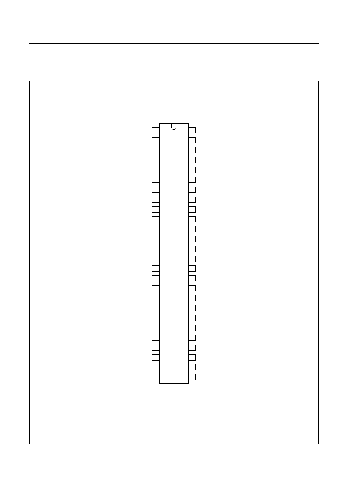
PINNING
SYMBOL PIN DESCRIPTION
V0 1 versatile open-drain input/output bit 0 (should be tied HIGH)
V1 2 versatile open-drain input/output bit 1 (should be tied HIGH)
V2 3 versatile open-drain input/output bit 2 (should be tied HIGH)
V3 4 versatile open-drain input/output bit 3 (should be tied HIGH)
V4 5 versatile open-drain input/output bit 4 (should be tied HIGH)
V5 6 versatile open-drain input/output bit 5 (should be tied HIGH)
V6 7 versatile open-drain input/output bit 6 (should be tied HIGH)
V7 8 versatile open-drain input/output bit 7 (should be tied HIGH)
res 9 reserved
res 10 reserved
res 11 reserved
res 12 reserved
V
SSD1
SCLK1 14 serial clock input 1 (NVRAM)
SDAT1 15 serial data input/output 1 (NVRAM)
SA 16 slave address input: LOW selects 58H; HIGH selects 60H
FP 17 field polarity input: LOW selects first half line; HIGH selects second half line at the start of an
HSMODE 18 horizontal sync mode control input: LOW selects HSYNC on rising edge
VSMODE 19 vertical sync mode control input. LOW selects VSYNC on rising edge
PDI 20 power-down imminent input: this input should be pulled LOW to indicate that the system is
PL 21 phase-lock output: HIGH indicates that the system is phase-locked to the CVBS input
V
SSA
CVBS1 23 CVBS input: this signal is applied via a 100 nF capacitor (nominal input 1 V (p-p)
CVBS2 24 this pin should be connected to ground if unused
BLACK 25 black level input: a 100 nF capacitor should be connected to V
I
ref
FRAME 27 Frame output for use in non-interlaced displays: during teletext off, teletext mixed with TV
V
SSD2
COR 29 contrast reduction: active LOW output which allows selective contrast reduction of the
PON 30 picture on output: HIGH indicates that a TV picture is present and that the SAA526xPS is in
RGBREF 31 RGB reference input: drive level reference for RGB outputs
B 32 blue dot rate character output of the blue colour information: the high voltage level is defined
13 digital ground 1
even field
about to lose power
22 analog ground
SSA
26 reference current input for analog circuits: for correct operation a 27 kΩ resistor should be
connected to V
SSA
picture and subtitles this pin is inactive. In full teletext mode this pin provides a 25 Hz square
wave. FRAME = 1 = odd, FRAME = 0 = even.
28 digital ground 2
television picture to enhance a mixed mode display
TV mode, mix mode, subtitle mode or news flash mode
by the RGBREF pin (can source 4 mA)
1998 Apr 22 5

Philips Semiconductors Product specification
10-page intelligent teletext decoders SAA5261; SAA5262; SAA5263
SYMBOL PIN DESCRIPTION
G 33 green dot rate character output of the green colour information: the high voltage level is
defined by the RGBREF pin (can source 4 mA)
R 34 red dot rate character output of the red colour information: the high voltage level is defined by
the RGBREF pin (can source 4 mA)
VDS 35 push-pull output for blanking the TV picture
HSYNC 36 horizontal sync input: the polarity of this pulse is set by input HSMODE
VSYNC 37 vertical sync input: the polarity of this pulse is set by input VSMODE
V
DDA
V
DDD(T)
OSCGND 40 ground for crystal oscillator
XTALI 41 12 MHz crystal oscillator input
XTALO 42 12 MHz crystal oscillator output
RESET 43 reset input
V
DDD(M)
PUINL 45 power-up in list mode control input: LOW selects auto TOP/Fastext on power-up; HIGH
DISDSR 46 disable default status row input: LOW enables display of status row
DIS8/30 47 disable packet 8/30 display input: LOW enables display of packet 8/30
DISLCBD 48 disable Link Control Byte (LCB) decode input: LOW enables decoding of the LCB in Fastext
SCLK2 49 serial clock input (I
SDAT2 50 serial data input/output (I
ME8/30T 51 mesh 8/30 and time displays input: HIGH will select a meshed display for the packet 8/30 and
E/
W 52 East/West language select input: LOW selects West language
38 analog supply voltage (+5 V)
39 digital supply voltage for teletext circuits (+5 V)
44 digital supply voltage for microcontroller (+5 V)
selects LIST mode on power-up
2
C-bus)
2
C-bus)
time
1998 Apr 22 6
Philips Semiconductors Product specification
10-page intelligent teletext decoders SAA5261; SAA5262; SAA5263
handbook, halfpage
V0
V1
V2
V3
V4
V5
V6
V7
res
res
res
res
V
SSD1
SCL1
SDA1
SA
FP
HSMODE
VSMODE
PDI
PL
V
SSA
CVBS1
CVBS2
BLACK
I
ref
1
2
3
4
5
6
7
8
9
10
11
12
13
SAA526xPS
14
15
16
17
18
19
20
21
22
23
24
25
26
MGL417
52
51
50
49
48
47
46
45
44
43
42
41
40
39
38
37
36
35
34
33
32
31
30
29
28
27
E/W
ME8/30T
SDA2
SCL2
DISLCBD
DIS8/30
DISDSR
PUINL
V
DDD(M)
RESET
XTALO
XTALI
OSCGND
V
DDD(T)
V
DDA
VSYNC
HSYNC
VDS
R
G
B
RGBREF
PON
COR
V
SSD2
FRAME
Fig.2 Pin configuration.
1998 Apr 22 7
Philips Semiconductors Product specification
10-page intelligent teletext decoders SAA5261; SAA5262; SAA5263
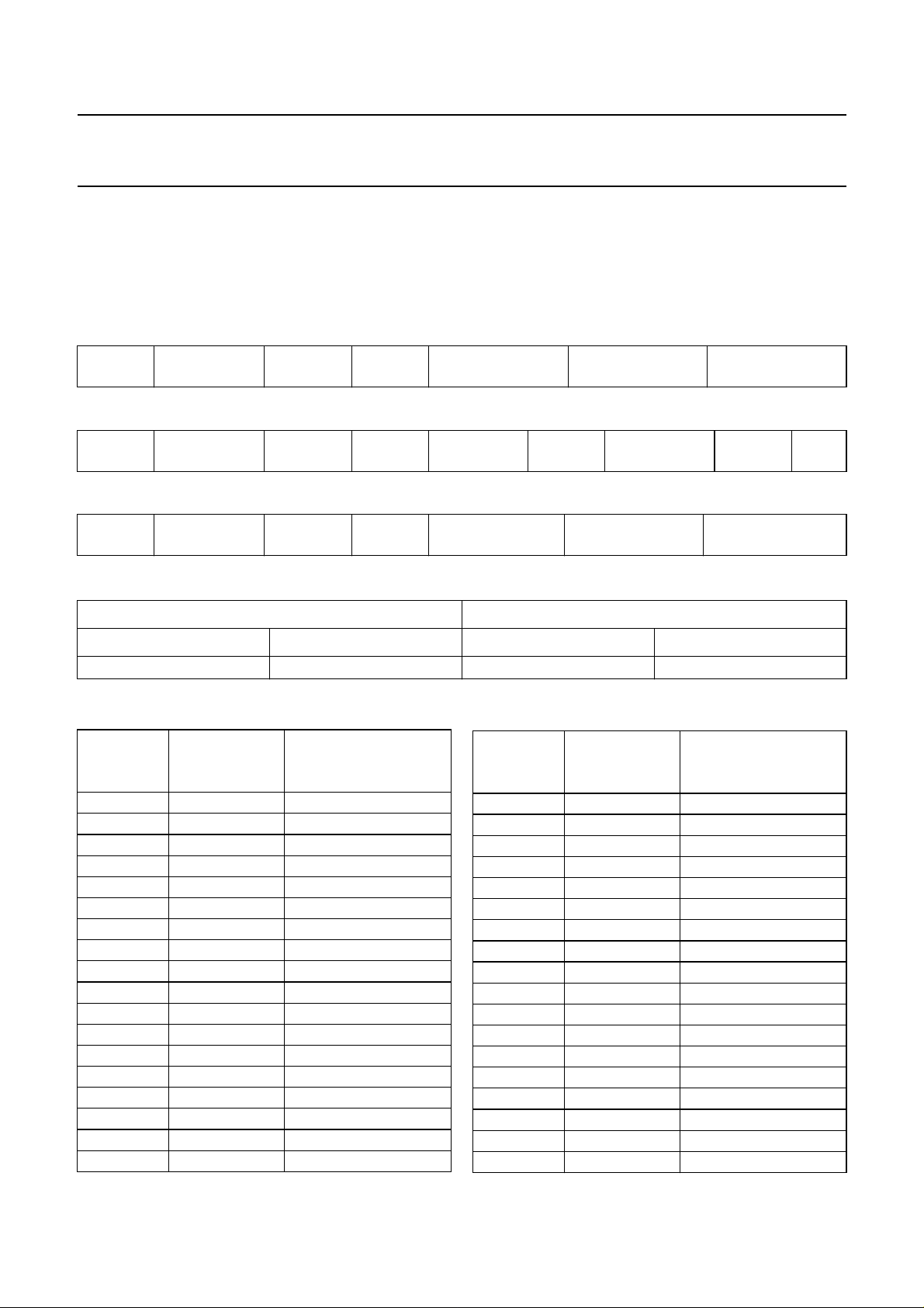
HIGH LEVEL COMMAND INTERFACE
The I2C-bus interface is used to pass control commands and data between the SAA526xPS and the television
microcontroller. The interface uses high level commands, which are backward compatible with the SAFARI interface.
The formats for the I2C-bus transmission are as follows:
Table 1 User command
START I
Table 2 System command
2
C-bus
ADDRESS
WRITE ACK COMMAND ACK STOP
START I2C-bus
ADDRESS
Table 3 System read
START I2C-bus
ADDRESS
2
Table 4 I
C-bus address
PIN 16 = LOW PIN 16 = HIGH
ADDRESS DESCRIPTION ADDRESS DESCRIPTION
01 01 100 read = 1; write = 0 0110 000 read = 1; write = 0
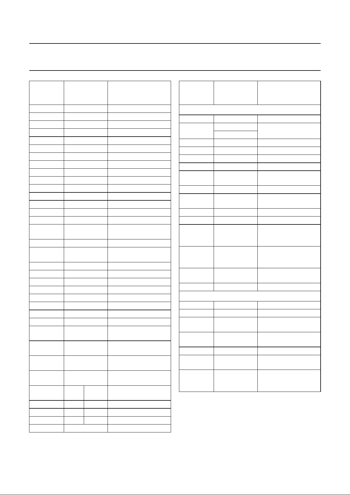
Table 5 Control commands
COMMAND
BYTE
(HEX)
DATA
BYTE
03 − picture
04 − TV status
07 − time
10 − program 0
11 − program 1
12 − program 2
13 − program 3
14 − program 4
15 − program 5
16 − program 6
17 − program 7
18 − program 8
19 − program 9
1A − program 10
1B − program 11
1C − program 12
1D − program 13
1E − program 14
WRITE ACK COMMAND ACK PARAMETER ACK STOP
READ ACK DATA NACK STOP
COMMAND
DESCRIPTION
COMMAND
BYTE
(HEX)
DATA
BYTE
COMMAND
DESCRIPTION
1F − program 15
20 − red
21 − green
22 − yellow
23 − subtitle
24 − text status
25 − hold
26 − reveal
27 − cancel
28 − index
29 − list toggle
2B − reveal toggle
2C − store
2D − previous
2F − subcode
30 − digit 1
31 − digit 2
32 − digit 3
1998 Apr 22 8
Philips Semiconductors Product specification
10-page intelligent teletext decoders SAA5261; SAA5262; SAA5263
COMMAND
BYTE
(HEX)
33 − digit 4
34 − digit 5
35 − digit 6
36 − digit 7
37 − digit 8
38 − digit 9
39 − digit 0
3A − size
3B − up
3C − down
3D − cyan
3E − mix
3F − text
4A 0 read PAL + line
89 00 to 41 select list
91 00 to 03 or
92 00 read broadcast status
93 00 or 01 read network
94 0 read PCS byte
98 OSD data OSD mode on
99 0 OSD mode off
9A 0 OSD display on
9B 0 OSD display off
9C 0 OSD cursor on
9D 0 OSD cursor off
9E 0, row, column OSD position
9F 0 followed by
A0 00 to FF bitwise parameter or
A1 00 to FF bitwise parameter
A2 00 to FF returns V7to V0 on
A3 PWM
B0 reg data or text register
B1 reg data and text register
B2 reg data read text register
B8 0 quick list
DATA
BYTE
00 to 80
20 bytes
No.
PWM
data
COMMAND
DESCRIPTION
force mode
identification
OSD data write
V7 to V0
and V7 to V0
2
C-bus read
I
PWM control
COMMAND
BYTE
(HEX)
SAA5262 and SAA5263 only
B9 0 get time
C0 0 = disable set ACI mode
C1 0 get ACI status
C2 0 select next ACI channel
C3 information type get ACI information
D0 0 get device version
D1 page type and
D2 page type get page number
D3 page type and
D4 page type get language
D5 row 24 control enable/disable row 24
D6 start column
D7 string type,
D8 option type and
D9 movement type move cursor
SAA5263 only
C8 EPG mode set EPG mode
C9 0 get EPG status
CA number and list
CB 0 get number of EPG
CC CNI index get found EPG CNIs
CD number and list
CE table type, item
DATA
BYTE
1 = enable
page number
language
and
length string
index length
and string
values
of features
of CNIs
type and string
index
COMMAND
DESCRIPTION
set page number
set language
set row 24 contents
set string contents
set option
set EPG feature list
CNIs found
set EPG CNI list
get EPG item
information
1998 Apr 22 9
 Loading...