

Philips SAA5244AGP, SAA5244AP Datasheet

INTEGRATED CIRCUITS
DATA SH EET
SAA5244A
Integrated VIP and teletext decoder
(IVT1.1)
Product specification
File under Integrated Circuits, IC02
March 1992
Philips Semiconductors Product specification
Integrated VIP and teletext decoder
(IVT1.1)
FEATURES
• Complete teletext decoder including page memory in a
single 40-pin DIL package
• Single +5 V power supply
• Digital data slicer and display clock phase-locked loop
reduces peripheral components to a minimum
• Both video and scan related synchronization modes are
supported
• On board single page memory including extension
packets for FASTEXT
• Single page acquisition system
• RGB interface to standard colour decoder ICs, push-pull
output drive
• Data capture performance similar to SAA5231 (VIP2)
2
• Simple software control via I
• Option for five national languages
• 32 supplementary characters for on-screen displays
• Optional storage of packet 24 in the display memory
• Page links in packets 27 and 8/30 are Hamming
decoded
• Separate text and video signal quality detectors,
625/525 video status and language version all readable
via I2C-bus
• Automatic ODD/EVEN output control with manual
override
• Control of display PLL free-run and rolling header via
I2C-bus
• VCS to SCS mode for stable 525 line status display
C-bus
SAA5244A
DESCRIPTION
The Integrated VIP and Teletext (IVT1.1) is a teletext
decoder (contained within a single-chip package) for
decoding 625-line based World System Teletext
transmissions. The teletext decoder hardware is based on
a reduced function version of the device SAA5246
(IVT1.0).
The Video Input Processor (VIP) section of the device
uses mixed analog and digital designs for the data slicer
and the display clock phase-locked loop functions. As a
result the number of external components is greatly
reduced and no critical or adjustable components are
required. A single page static RAM is incorporated in the
device thereby giving a genuine single-chip teletext
decoder device.
ORDERING INFORMATION
EXTENDED TYPE
NUMBER
SAA5244AP 40 DIL plastic SOT129
SAA5244AGP 44 QFP plastic SOT205A
Notes
1. SOT129-1; 1996 December 16.
2. SOT205-1; 1996 December 16.
March 1992 2
PINS PIN POSITION MATERIAL CODE
PACKAGE
(1)
(2)

Philips Semiconductors Product specification
Integrated VIP and teletext decoder
SAA5244A
(IVT1.1)
QUICK REFERENCE DATA
SYMBOL PARAMETER MIN. TYP. MAX. UNIT
V
DD
I
DD
V
syn
V
vid
f
XTAL
T
amb
positive supply voltage 4.5 5 5.5 V
supply current − 74 148 mA
sync amplitude 0.1 0.3 0.6 V
video amplitude 0.7 1 1.4 V
crystal frequency − 27 − MHz
operating ambient temperature range −20 − 70 °C
March 1992 3
Philips Semiconductors Product specification
Integrated VIP and teletext decoder
(IVT1.1)
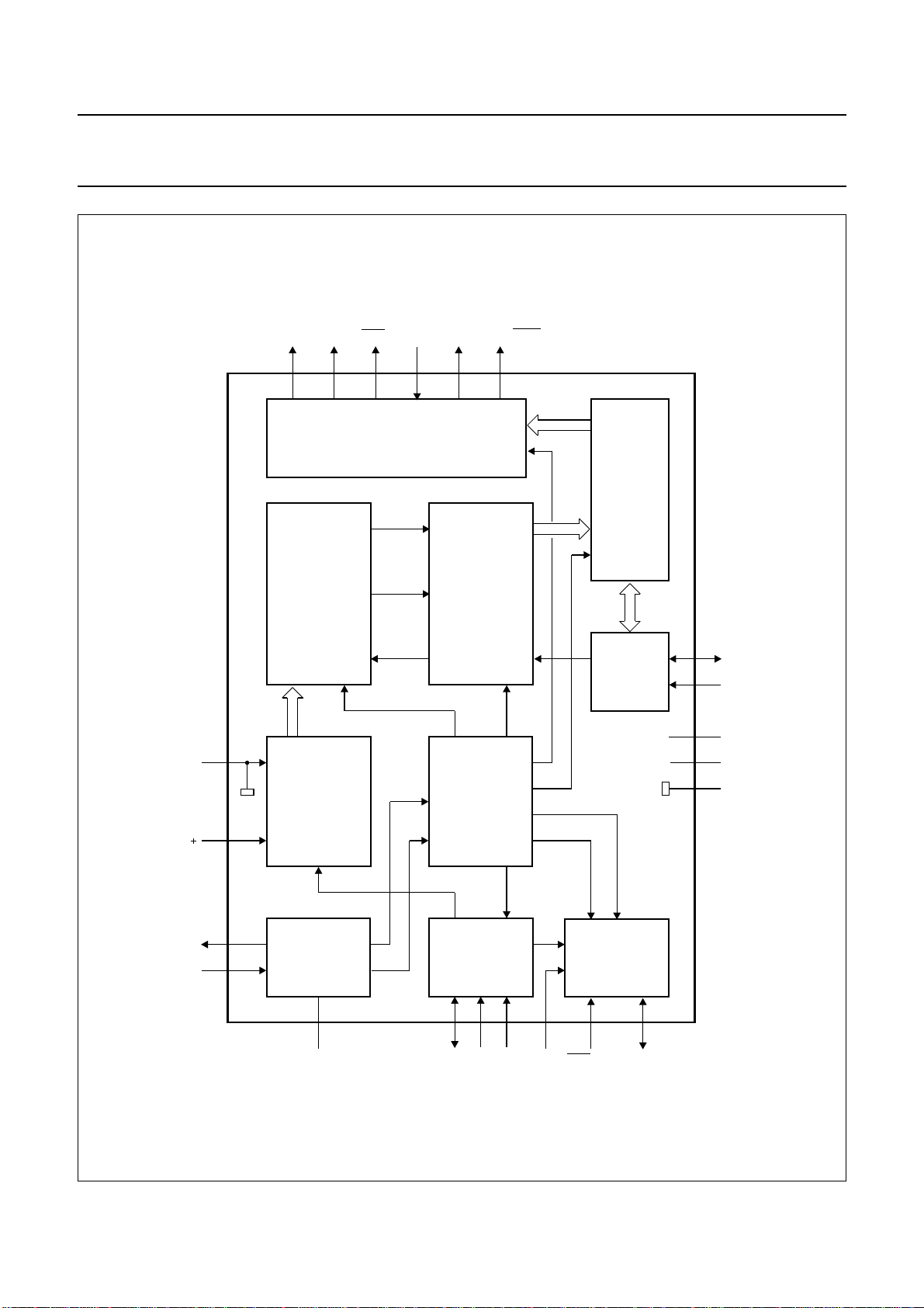
handbook, full pagewidth
Y
BLAN
23 19 21 18 15-17 22
DATA
SLICER
AND
CLOCK
REGENERATOR
RGBREF RGB
DISPLAY
ODD / EVENCOR
TELETEXT
ACQUISITION
AND
DECODING
PAGE
MEMORY
SAA5244A
V
SS
REF
OSCOUT
OSCIN
DCVBS
5
6
2
3
2
I
C-BUS
INTERFACE
ANALOG
TO
DIGITAL
CONVERTER
CRYSTAL
OSCILLATOR
4 7 9 8 11 13 12
OSCGND BLACK IREF CVBS POL STTV / LFB
TIMING
CHAIN
INPUT
CLAMP
AND SYNC
SEPARATOR
SAA5244A
DISPLAY
CLOCK
PHASE
LOCKED
LOOP
VCR / FFB
25
SDA
24
SCL
1
V
DD
10
14
20
V
DD
V
SS
MLA228 - 1
Fig.1 Block diagram for SOT129 (DIL40) package.
March 1992 4
Philips Semiconductors Product specification
Integrated VIP and teletext decoder
SAA5244A
(IVT1.1)
PINNING
SYMBOL SOT129 SOT205A DESCRIPTION
V
DD
OSCOUT 2 19 27 MHz crystal oscillator output
OSCIN 3 20 27 MHz crystal oscillator input
OSCGND 4 21 0 V crystal oscillator ground
V
SS
REF−−− negative reference voltage for the ADC. The pin should be connected to 0 V
REF+ 6 23 positive reference voltage for the ADC. The pin should be connected to +5 V
BLACK 7 24 video black level storage pin, connected to ground via a 100 nF capacitor
CVBS 8 25 composite video input pin. A positive-going 1 V (peak-to-peak) input is required,
IREF 9 26 reference current input pin, connected to ground via a 27 kΩ resistor
V
DD
POL 11 28 STTV/LFB/FFB polarity selection pin
STTV/LFB 12 29 sync to TV output pin/line flyback input pin. Function controlled by an internal
VCR/FFB 13 32 PLL time constant switch/field flyback input pin. Function controlled by an
V
SS
R 15 34 dot rate character output of the RED colour information
G 16 35 dot rate character output of the GREEN colour information
B 17 36 dot rate character output of the BLUE colour information
RGBREF 18 37 input DC voltage to define the output high level on the RGB pins
BLAN 19 38 dot rate fast blanking output
V
SS
COR 21 40 programmable output to provide contrast reduction of the TV picture for mixed
ODD/
EVEN 22 41 25 Hz output synchronized with the CVBS input’s field sync pulses to produce a
Y 23 42 dot rate character output of teletext foreground colour information open drain
SCL 24 43 serial clock input for the I
SDA 25 44 serial data port for the I
n.c. − 4 to 7
i.c. 26 to 40 1 to 3
1 18 +5 V supply
5 22 0 V ground
connected via a 100 nF capacitor
10 27 +5 V supply
register bit (scan sync mode)
internal register bit (scan sync mode)
14 33 0 V ground
20 39 0 V ground
text and picture displays or when viewing newsflash/subtitle pages; open drain
output
non-interlaced display by adjustment of the vertical deflection currents
output
device
power-down of the device
not connected
30, 31
internally connected. Must be left open-circuit in application
8 to 17
2
C-bus. It can still be driven during power-down of the
2
C-bus; open drain output. It can still be driven during
March 1992 5
Philips Semiconductors Product specification
Integrated VIP and teletext decoder
(IVT1.1)
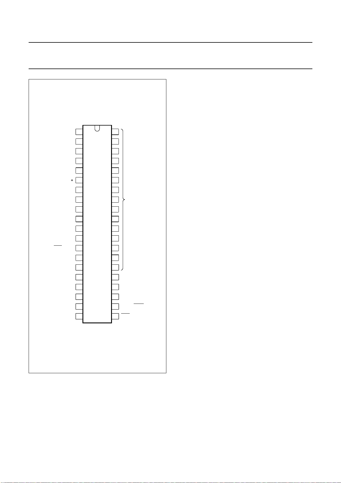
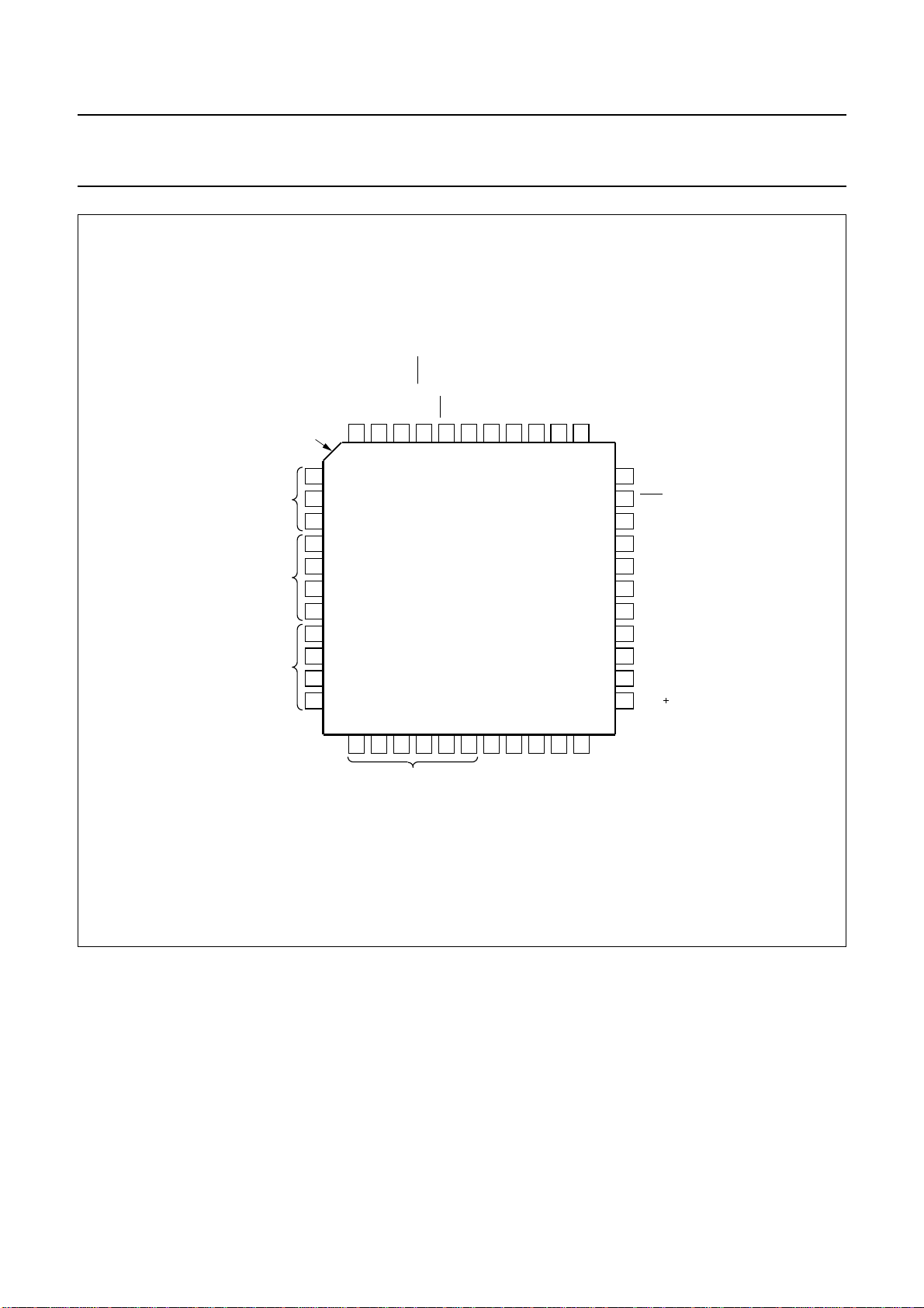
handbook, halfpage
V
DD
OSCOUT
OSCIN
OSCGND
V
SS
REF
BLACK
CVBS
IREF
V
DD
POL
STTV / LFB
VCR / FFB
V
SS
R
1
2
3
4
5
6
7
8
9
10
SAA5244A
11
12
13
15
40
39
38
37
36
35
34
i.c.
33
32
31
30
29
28
2714
26
SAA5244A
RGBREF
BLAN
V
SS
G
16
B
17
18
19
20
MLA035 - 3
SDA
25
SCL
24
Y
23
ODD / EVEN
22
COR
21
Fig.2 Pin configuration; SOT129 (DIL40).
March 1992 6
Philips Semiconductors Product specification
Integrated VIP and teletext decoder
(IVT1.1)
SDA
handbook, full pagewidth
i.c.
n.c.
i.c.
index
corner
1
2
3
4
5
6
7
8
9
10
11
SCL
44
43
ODD / EVEN
Y
42
41
SAA5244A
COR
40
SAA5244A
G
VSS
RGBREF
BLAN
B
R
39
38
37
36
35
34
33
V
SS
32
VCR / FFB
31
n.c.
30
n.c.
29
STTV / LFB
28
POL
27
V
DD
26
IREF
25
CVBS
24
BLACK
23
REF
20
21
OSCIN
OSCGND
22
VSS
12
13
14
15
16
17
18
19
DD
i.c.
V
OSCOUT
Fig.3 Pin configuration; SOT205A (QFPL44).
MLA227 - 2
March 1992 7
Philips Semiconductors Product specification
Integrated VIP and teletext decoder
SAA5244A
(IVT1.1)
LIMITING VALUES
In accordance with the Absolute Maximum System (IEC 134)
SYMBOL PARAMETER MIN. MAX. UNIT
V
DD
V
I
V
O
I
O
I
IOK
T
amb
T
stg
V
stat
Note
1. The human body model ESD simulation is equivalent to discharging a 100 pF capacitor through a 1.5 kΩ resistor;
this produces a single discharge transient. Reference Philips Semiconductors test method UZW-B0/FQ-A302
(compatible with MIL-STD method 3015.7).
supply voltage (all supplies) −0.3 6.5 V
input voltage (any input) −0.3 VDD+0.5 V
output voltage (any output) −0.3 VDD+0.5 V
output current (each output) −±10 mA
DC input or output diode current −±20 mA
operating ambient temperature range −20 70 °C
storage temperature range −55 125 °C
electrostatic handling
human body model (note 1) −2000 2000 V
Failure Rate
The failure rate at T
=55°C will be a maximum of 1000 FITS (1 FIT = 1 x 10⁻⁹ failures per hour).
amb
March 1992 8
Philips Semiconductors Product specification
Integrated VIP and teletext decoder
SAA5244A
(IVT1.1)
CHARACTERISTICS
V
=5 V±10%; T
DD
SYMBOL PARAMETER CONDITIONS MIN. TYP. MAX. UNIT
Supply
V
DD
I
DD
supply voltage range (VDD−VSS) 4.5 5 5.5 V
total supply current − 74 148 mA
Inputs
CVBS
V
t
syn
syn
sync amplitude 0.1 0.3 0.6 V
delay from CVBS to TCS
output from STTV buffer
(nominal video, average of
leading/trailing edge)
t
syd
change in sync delay between
all black and all white video
input at nominal levels
V
vid(p-p)
video input amplitude
(peak-to-peak)
display PLL catching range ±7 −− %
Z
src
C
I
source impedance −−250 Ω
input capacitance −−10 pF
IREF
R
g
resistor to ground − 27 − kΩ
POL
V
IL
V
IH
I
LI
C
I
input voltage LOW −0.3 − 0.8 V
input voltage HIGH 2.0 − VDD+0.5 V
input leakage current VI= 0 to V
input capacitance −−10 pF
LFB
V
IL
V
IH
I
LI
I
I
t
LFB
input voltage LOW −0.3 − 0.8 V
input voltage HIGH 2.0 − VDD+0.5 V
input leakage current VI= 0 to V
input current note 1 −1 − 1mA
delay between LFB front edge
and input video line sync
VCR/FFB
V
IL
V
IH
I
LI
I
I
input voltage LOW −0.3 − 0.8 V
input voltage HIGH 2.0 − VDD+.5 V
input leakage current VI= 0 to V
input current note 1 −1 − 1mA
= −20 to +70 °C, unless otherwise specified
amb
DD
DD
DD
−150 0 150 ns
0 − 25 ns
0.7 1 1.4 V
−10 − 10 µA
−10 − 10 µA
− 250 − ns
−10 − 10 µA
March 1992 9
Philips Semiconductors Product specification
Integrated VIP and teletext decoder
SAA5244A
(IVT1.1)
SYMBOL PARAMETER CONDITIONS MIN. TYP. MAX. UNIT
Inputs
RGBREF (NOTE 2)
V
I
I
LI
I
DC
SCL
V
IL
V
IH
I
LI
f
SCL
t
r
t
f
C
I
Inputs/outputs
input voltage −0.3 − VDD+0.5 V
input leakage current VI= 0 to V
DD
−10 − 10 µA
DC current −−10 mA
input voltage LOW −0.3 − 1.5 V
input voltage HIGH 3.0 − VDD+0.5 V
input leakage current VI= 0 to V
DD
−10 − 10 µA
clock frequency 0 − 100 kHz
input rise time 10% to 90% −−2µs
input fall time 90% to 10% −−2µs
input capacitance −−10 pF
C
RYSTAL OSCILLATOR (OSCIN; OSCOUT)
f
XTAL
G
v
G
m
C
l
C
FB
crystal frequency − 27 − MHz
small signal voltage gain 3.5 −− −
mutual conductance f = 100 kHz 1.5 −− mA/V
input capacitance −−10 pF
feedback capacitance −−5pF
BLACK
C
blk
I
LI
storage capacitor to ground − 100 − nF
input leakage current VI= 0 to V
SDA
V
IL
V
IH
I
LI
C
l
t
r
t
f
V
OL
t
f
C
L
input voltage LOW −0.3 − 1.5 V
input voltage HIGH 3.0 − VDD+0.5 V
input leakage current VI= 0 to V
input capacitance −−10 pF
input rise time 10% to 90% −−2µs
input fall time 90% to 10% −−2µs
output voltage LOW IOL= 3 mA 0 − 0.5 V
output fall time 3 to 1 V −−200 ns
load capacitance −−400 pF
DD
DD
−10 − 10 µA
−10 − 10 µA
March 1992 10
 Loading...