

Philips SAA4995W Service Manual

INTEGRATED CIRCUITS
DATA SH EET
SAA4995WP
PANorama-IC (PAN-IC)
Preliminary specification
File under Integrated Circuits, IC02
1997 Jun 10

Philips Semiconductors Preliminary specification
PANorama-IC (PAN-IC) SAA4995WP
FEATURES
• Horizontal sample rate conversion in both zoom and
compress direction, with a sample rate conversion factor
between 0.5 and 2 (in 384 steps)
• Dynamic sample rate conversion for panorama mode
display e.g. 4 : 3 material on a 16 : 9 display
• Dynamic sample rate conversion for amaronap mode
display of e.g. 16 : 9 material on a 4 : 3 display
• Operates with 1fh and 2f
h
• Programmable via microcontroller SNERT
(Synchronous No parity Eight bit Receive Transmit) bus.
GENERAL DESCRIPTION
The PAN-IC is an add-on IC to be used, for example,
between analog-to-digital conversion and a serial (field)
memory. The device performs the following tasks:
• Linear horizontal sample rate conversion in both zoom
and compress direction, with a sample rate conversion
factor between 0.5 and 2
• Dynamic sample rate conversion for panorama mode
display of e.g. 4 : 3 material on a 16 : 9 display
• Dynamic sample rate conversion for amaronap mode
display of e.g. 16 : 9 material on a 4 : 3 display.
The PAN-IC has the ability to increase the data rate from
the ADC to a maximum of twice the data rate at the output.
To achieve this a clock rate at twice the normal output
clock rate is needed to write data to the memory.
All actions to generate a lower data rate, produces disable
cycles in Write Enable (WE).
QUICK REFERENCE DATA
SYMBOL PARAMETER MIN. TYP. MAX. UNIT
V
I
DD
f
CLK
T
DD
amb
supply voltage 4.5 5 5.5 V
supply current − 110 − mA
operating clock frequency −−33 MHz
operating ambient temperature 0 − 70 °C
ORDERING INFORMATION
PACKAGE
TYPE NUMBER
NAME DESCRIPTION VERSION
SAA4995WP PLCC44 plastic leaded chip carrier; 44 leads SOT187-2
1997 Jun 10 2

Philips Semiconductors Preliminary specification
PANorama-IC (PAN-IC) SAA4995WP
BLOCK DIAGRAM
handbook, full pagewidth
Y
I7
to
Y
I0
UI1/U
and
VI1/V
WE
I
SNDA
SNCL
VRST
I0
I0
CL16
37 to 44
1 to 4
7
CL16 CLK
34
35
36
CLK
5 31
CL16
CL16
C
C
'0'
1
2
SECAM
NOTCH
CLK
V
DD1
10 12
MUX
notch
GND1
V
CLK
SAA4995WP
INTEGRATORMUX
X0rX0IX1rX1IX2rX
SNERT BUS INTERFACE
GND2
DD2
15 16
FRONT-END
FRONT-END
INTEGRATOR
LINE CONTROL
2I
in-phase
V
VPD
VPD
out-phase
DD3
33 30
SPL
init
GND3
BACK-END
BACK-END
+
C
0
notch
V
DD4
VPD
VPD
8 9
GND4
6 32
∆Y∆UV
DTO
C0
C1
C2
29 to 22
21 to 18
Y
O7
to
Y
O0
VO0/V
O1
and
UO0/U
O1
17
WE
O
14
WE
od
13
T1
11
T0
Fig.1 Block diagram.
1997 Jun 10 3
TEST
SCANIN
MGK176

Philips Semiconductors Preliminary specification
PANorama-IC (PAN-IC) SAA4995WP
PINNING
SYMBOL PIN DESCRIPTION
U
I1
U
I0
V
I1
V
I0
1 U input bit 1
2 U input bit 0
3 V input bit 1
4 V input bit 0
CL16 5 half system clock
V
DD4
WE
I
6 supply voltage 4
7 write enable input
TEST 8 test mode switch
SCANIN 9 input for scan chain
V
DD1
10 supply voltage 1
T0 11 test mode switch 0
GND1 12 ground 1
T1 13 test mode switch 1
WE
V
DD2
od
14 write enable odd samples
15 supply voltage 2
GND2 16 ground 2
WE
V
O0
V
O1
U
O0
U
O1
Y
O0
Y
O1
O
17 write enable output
18 V output bit 0
19 V output bit 1
20 U output bit 0
21 U output bit 1
22 luminance output bit 0
23 luminance output bit 1
SYMBOL PIN DESCRIPTION
Y
O2
Y
O3
Y
O4
Y
O5
Y
O6
Y
O7
24 luminance output bit 2
25 luminance output bit 3
26 luminance output bit 4
27 luminance output bit 5
28 luminance output bit 6
29 luminance output bit 7
GND3 30 ground 3
CLK 31 system clock
GND4 32 ground 4
V
DD3
33 supply voltage 3
SNDA 34 data input from interface
SNERT bus
SNCL 35 clock input from interface
SNERT bus
VRST 36 reset input in the vertical
blanking interval
Y
I7
Y
I6
Y
I5
Y
I4
Y
I3
Y
I2
Y
I1
Y
I0
37 luminance input bit 7
38 luminance input bit 6
39 luminance input bit 5
40 luminance input bit 4
41 luminance input bit 3
42 luminance input bit 2
43 luminance input bit 1
44 luminance input bit 0
1997 Jun 10 4
Philips Semiconductors Preliminary specification
PANorama-IC (PAN-IC) SAA4995WP
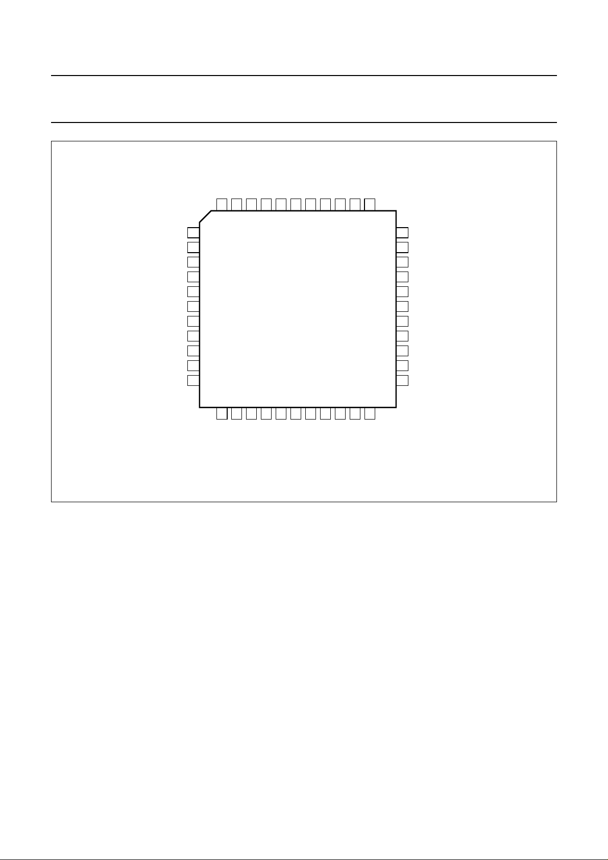
handbook, full pagewidth
WE
TEST
SCANIN
V
DD1
T0
GND1
T1
WE
od
V
DD2
GND2
WE
DD4
CL16
VI0VI1UI0UI1Y
V
6
5
4
3
2
7
I
8
9
10
11
12
13
14
15
16
17
O
18
19
O1UO0UO1YO0YO1YO2
O0
V
V
SAA4995WP
21
20
22
I0
I1
YI2YI3Y
Y
1
44
43
42
23
24
25
26
O3
YO4YO5Y
Y
I4
41
40
39
Y
I5
Y
38
I6
37
Y
I7
36
VRST
SNCL
35
34
SDNA
V
33
DD3
GND4
32
CLK
31
30
GND3
Y
29
O7
27
28
MGK175
O6
Fig.2 Pin configuration.
FUNCTIONAL DESCRIPTION
The PAN-IC is an add-on IC to be used, for example,
between analog-to-digital conversion and a serial (field)
memory. The device performs the following tasks:
• Linear horizontal sample rate conversion in both zoom
and compress direction, with a sample rate conversion
factor between 0.5 and 2
• Dynamic sample rate conversion for panorama mode
display of e.g. 4 : 3 material on a 16 : 9 display
• Dynamic sample rate conversion for amaronap mode
display of e.g. 16 : 9 material on a 4 : 3 display.
The PAN-IC has the ability to increase the data rate from
the ADC (maximum 16 MHz in a 16/32 MHz concept) to a
maximum of twice the data rate. For this, a 32 MHz clock
rate is needed to write to the memory. All actions to
generate a lower data rate produces disable cycles in write
enable.
In panorama and amaronap modes, the sample rate
conversion factor is modulated along the video line.
In the centre of the line a high quality compression (e.g.
4
with a factor
⁄3) has to be made. Towards the sides of the
line, more and more expansion and compression
respectively is made. The sample rate conversion factor
over a line will have a bathtub shape, with parameters
illustrated in Fig.3:
• X0l and X0r, where in-between a constant data rate is
maintained (area I) and starting points from where a
curve can be programmed for its 2nd derivative (in
areas II and V)
• X1l and X1r, points from where a new curve can be
programmed for its 2nd derivative (for areas III and IV)
• X2l corresponds to the first sample in the output data
stream, defined by start of WE
I
• X2r corresponds to the last sample in the output data
stream, defined by the programmed number of samples
• C1, which controls the second derivatives of the data
rate in areas II and V
• C2, which controls the second derivatives of the data
rate in areas III and IV.
1997 Jun 10 5
 Loading...