

Philips SAA1504T Datasheet

INTEGRATED CIRCUITS
DATA SH EET
SAA1504T
Safety IC
Objective specification
File under Integrated Circuits, IC17
2000 Mar 07

Philips Semiconductors Objective specification
Safety IC SAA1504T
FEATURES
• Zero voltage start-up
• Discharge and charge overcurrent protection
• Automatic release of current protection at removal of
charger or load
• Low current consumption in normal operating mode
• Very low current consumption when battery voltage is
lower than 2.3 V
• Accurate voltage detection levels
• Continuous monitoring of batteryvoltage and charge or
discharge current
• External power FETs are driven with an elevated supply
voltage, reducing the on-resistance
• Able to accommodate 20 V charge voltage
• Read out of charge (disable) status
• Small package (SO8)
• Low external components count
• Temperature protection
• Charger reverse connection protection.
GENERAL DESCRIPTION
The SAA1504T is manufactured in a BCD Power Logic 70
process and is intended to be used as a protection circuit
forsingle cell Li-ion batterypacks. The current and voltage
ratings are especially designed for use in battery packs for
portable telephones such as GSM.
The circuit continuously monitors the battery voltage,
current and junction temperature and will disconnect the
battery in case of an overload situation:
• Overdischarge protection prevents deep discharge of
the cell; deep discharge of a Li-ion cell degrades the life
cycle
• Overcharge protection for safety reasons
• Overcurrent protection on charge or discharge current
rate
• Temperature protection for preventing charge or
discharge at high temperatures
• Short circuit protection.
It must be stated that this is a safety IC to be integrated
inside a battery pack. It is not primarily intended as an end
of charge provision.
ORDERING INFORMATION
TYPE
NUMBER
SAA1504T SO8 plastic small outline package; 8 leads; body width 3.9 mm SOT96-1
NAME DESCRIPTION VERSION
PACKAGE
2000 Mar 07 2

This text is here in white to force landscape pages to be rotated correctly when browsing through the pdf in the Acrobat reader.This text is here in
_white to force landscape pages to be rotated correctly when browsing through the pdf in the Acrobat reader.This text is here inThis text is here in
white to force landscape pages to be rotated correctly when browsing through the pdf in the Acrobat reader. white to force landscape pages to be ...
2000 Mar 07 3
handbook, full pagewidth
CEXT
BLOCK DIAGRAM
Philips Semiconductors Objective specification
Safety IC SAA1504T
LOGIC
7
ESD
reset
disable
mode
CHARGE
SHIFTER
−185 mV
V
CC
PUMP
LEVEL
CURRENT
PROTECTION
V
ref
V
cp
SAA1504T
K2 × V
ptat
ESD
ESD
2
DO
3
CO
5
ST
ESD
CC
SS
8
ESD 6.8 V
6
1
4
V
n.c.
V
VM
LEVEL
SHIFTER
K1 × V
ptat
4.18 V
ESD
2.3 V
3.95 V
V
ref
set
disable
mode
175 mV
Fig.1 Block diagram.
MGS969
Philips Semiconductors Objective specification
Safety IC SAA1504T
PINNING FUNCTIONAL DESCRIPTION
SYMBOL PIN DESCRIPTION
V
SS
1 ground supply
DO 2 output to gate of discharge power FET
CO 3 output to gate of charge power FET
VM 4 negative sense input
ST 5 status output
n.c. 6 not connected
CEXT 7 connection for external delay capacitor
V
CC
handbook, halfpage
8 positive battery sense input
V
1
SS
2
SAA1504T
3
CO
4
VM
MGS970
V
8
CC
CEXTDO
7
n.c.
6
ST
5
Fig.2 Pin configuration.
The basic function of the SAA1504T is to protect a single
Li-ion cell against overcharge and overdischarge for
reasons of life time and safety. The voltage across the cell
terminals (V
) is monitored continuously and compared
bat
to an accurate internal reference voltage.
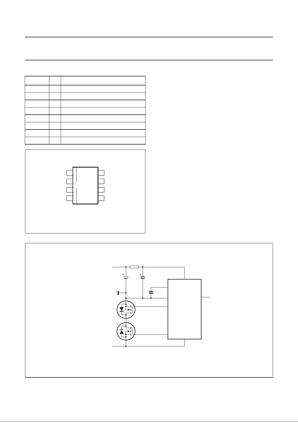
The circuit diagram (see Fig.3) of a Li-ion battery pack
shows the SAA1504T and 2 power NMOS transistors
which are connected in anti series. Both transistors must
have their backgate connected to their source, resulting in
2 backgate diodes in anti series.
The timing diagram (see Fig.6) shows the detection levels
for the various modes of operation.
Battery voltage between 2.6 and 4.18 V
The safety IC is in the normal operating mode for
V
= 2.6 to 4.18 V, a charge or discharge current below
bat
the current-protection level and a junction temperature
below the temperature protection activation level. In this
mode transistors SW1 and SW2 are driven with an
elevated supply voltage (with a charge pump) which
guarantees a low on-resistance in the main current path.
This is important for fully utilizing the high energy density
of the Li-ion battery technology.
handbook, full pagewidth
+ charger/load
− charger/load
V
bat
R1
1 kΩ
SW2
SW1
Fig.3 Safety IC connection diagram.
2000 Mar 07 4
C1
0.47 µF
C2
CEXT
V
SS
DO
CO
7
1
2
SAA1504T
3
V
CC
8
ST
5
4
VM
MGS971

Philips Semiconductors Objective specification
Safety IC SAA1504T
Battery voltage below 2.3 V
When V
< 2.3 V the safety IC is in the Power-down
bat
mode: SW2 is open to block a further discharge.
The battery voltage will increase stepwise, because of the
sudden disconnection of the load. The safety IC will not
re-enter the normal operating mode at this event unless
the battery voltage exceeds the power-down release level
of 2.6 V and a charge current is present. So when no
charger is present in the Power-down mode, the safety IC
stays in this mode, independent of the battery voltage.
ConnectingachargerinthePower-downmodeisdetected
by a negative voltage on pin VM. Because the voltage at
pin VM is defined by a charge current via the backgate
diode of SW2, a charge current of a few nAs is already
detected. When a charge current is detected and
V
> 2.6 V, the system will go from the Power-down
bat
mode to the normal operating mode.
In the Power-down mode the supply current is reduced to
150 nA (typical value) for minimizing the discharge of the
battery by the safety IC. This is achieved by disabling all
analog circuitry, except the circuitry for detecting the
presence of a charger and for detecting V
bat
> 2.6 V.
Because the charge pump is disabled and battery
charging should be possible, SW1 is switched on with a
reduced Vgs voltage.
Zero voltage start-up
The safety IC has to be able to charge the battery at 0 V.
This means that when connecting a charger in case of a
completely empty battery, SW1 has to be open.
In the Power-down mode output CO is connected via a
diode to VCC, so that the charge transistor will be active
when VVM is negative.
Maximum charge or discharge current and temperature protection
When the maximum charge or discharge current is
exceeded or when the maximum temperature is detected
the disable mode is activated and will open both switches.
Exceeding the maximum charge or discharge current is
detected by a voltage drop or rise on pin VM when both
switches are closed.
A release of this mode can only be achieved by removing
the load (or charger) and at a junction temperature below
60 °C. The disable mode is followed by a return to its
previous mode.
Normal operating mode
In case of correct temperature, battery voltage and charge
or discharge current, the system will be in the normal
operating mode (see Fig.4).
Battery voltage above 4.18 V
When the battery is charged to V
> 4.18 V, the safety IC
bat
will enter the charge inhibit mode: SW1 is open and
charging is disabled.
Connecting a load in the charge inhibit mode is detected
by the reversal of the voltage across SW1 and will
immediately close SW1, so entering the discharge enable
mode. A short time is needed to charge the gate of SW1.
During this time the backgate diode between drain and
source of SW1 conducts.
The safety IC will remain in the discharge enable mode
unless:
• V
< 3.95 V, which results in re-entering the normal
bat
operating mode. This transition is not externally
noticeable, because both switches remain closed.
• A charger is connected, which will immediately open
SW1. As an additional safety precaution V
> 4.18 V
bat
also yields the same reaction, because otherwise a
smallcurrentof a charger may be undetected, leading to
overcharging the Li-ion cell.
Both the charge and discharge outputs will be HIGH
(CO = 1 and DO = 1), so both switches are closed.
Power-down mode
When V
< 2.3 V the safety IC will enter the Power-down
bat
mode(seeFig.4).Thepower-down detection level of 2.3 V
hasadelay of 5 ms (typical value). The Power-down mode
will also be entered without delay when V
bat
< 1.9 V.
In this mode only charging of the battery is allowed
(CO = 1 and DO = 0).
The safety IC will return to the normal operating mode as
soon as V
> 2.6 V and a charge current is detected at
bat
the same time.
2000 Mar 07 5
 Loading...