

Philips saa1502bts DATASHEETS

INTEGRATED CIRCUITS
DATA SH EET
SAA1502ATS
Safety IC for Li-ion
Preliminary specification
File under Integrated Circuits, IC11
1998 Jan 15

Philips Semiconductors Preliminary specification
Safety IC for Li-ion SAA1502ATS
FEATURES
• Integrated power switches
• Temperature protection
• Zero voltage start-up
• Discharge and charge overcurrent protection
• Automatic release of current protection at removal of
charger or load
• Extremely low current consumption when battery
voltage is lower than 2.3 V
• Low current consumption in normal operation mode
• Accurate voltage detection levels
• Low resistance in current path
• Able to accommodate 17.5 V charge voltage
• Read out of charge disable status
• Small package (SSOP16)
• Low external components count
• Continuous monitoring of the battery voltage and
(dis)charge current.
GENERAL DESCRIPTION
The SAA1502ATS is manufactured in a Bipolar, CMOS
and DMOS (BCD) Power Logic 70 process and is intended
to be used as a protection circuit for single cell Li-ion
battery packs. The current and voltage ratings are
especially designed for use in battery packs for portable
telephones such as GSM.
The circuit monitors the battery voltage, current and
temperature and will disconnect the battery in case of an
overload situation:
• Overdischarge protection prevents deep discharge of
the cell; deep discharge of a Li-ion cell degrades the
lifetime
• Overcharge protection for safety reasons
• Overcurrent protection on charge as well as discharge
current rate
• Temperature protection for preventing charge or
discharge at high temperatures.
It must be stated that the unit is a safety unit to be
integrated inside a battery pack. It is not intended as an
end of charge provision.
ORDERING INFORMATION
TYPE
NUMBER
SAA1502ATS SSOP16 plastic shrink small outline package; 16 leads; body width 5.3 mm SOT338-1
NAME DESCRIPTION VERSION
PACKAGE
1998 Jan 15 2
This text is here in white to force landscape pages to be rotated correctly when browsing through the pdf in the Acrobat reader.This text is here in
d
_white to force landscape pages to be rotated correctly when browsing through the pdf in the Acrobat reader.This text is here inThis text is here in
white to force landscape pages to be rotated correctly when browsing through the pdf in the Acrobat reader. white to force landscape pages to be ...
1998 Jan 15 3
book, full pagewidth
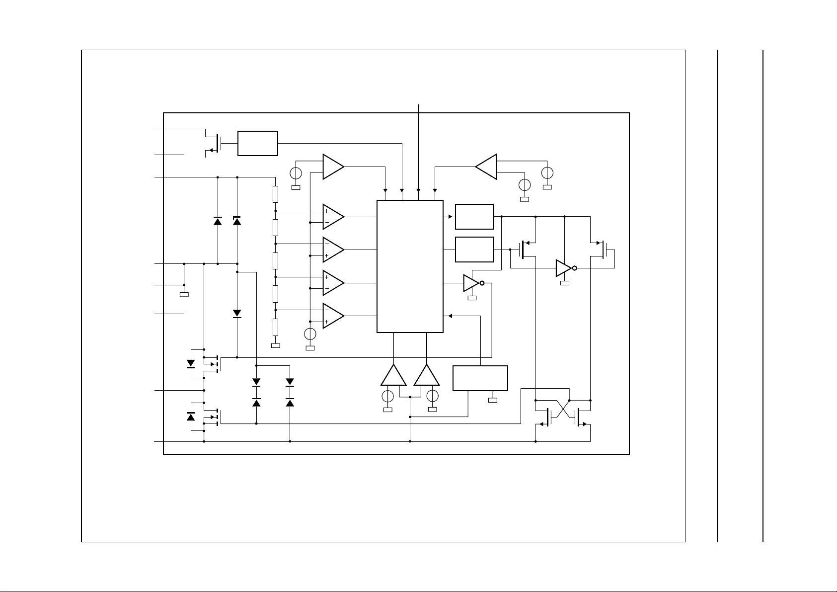
BLOCK DIAGRAM
Safety IC for Li-ion SAA1502ATS
Philips Semiconductors Preliminary specification
V
V
n.c.
V
SS1
SS2
ST
CC
LF
V
15
LEVEL
ESD
SW2
SHIFTER
ESD
V
ESD
ref
4.18 V
3.95 V
3.6 V
2.3 V
V
ref
set
temperature
protection
charge
disable
charge
enable
discharge
enable
discharge
disable
V
ref
1, 16
2
14
5, 6
4, 13
7, 8,
9, 10
d
VM
ESD 6.8 V
C
LOGIC
ext
3
reset
temperature
protection
CHARGE
PUMP
LEVEL
SHIFTER
CURRENT
PROTECTION
V
ref
SAA1502ATS
V
ref
V
cp
V
ref
VM
SW1
11, 12
MGM307
Fig.1 Block diagram.
Philips Semiconductors Preliminary specification
Safety IC for Li-ion SAA1502ATS
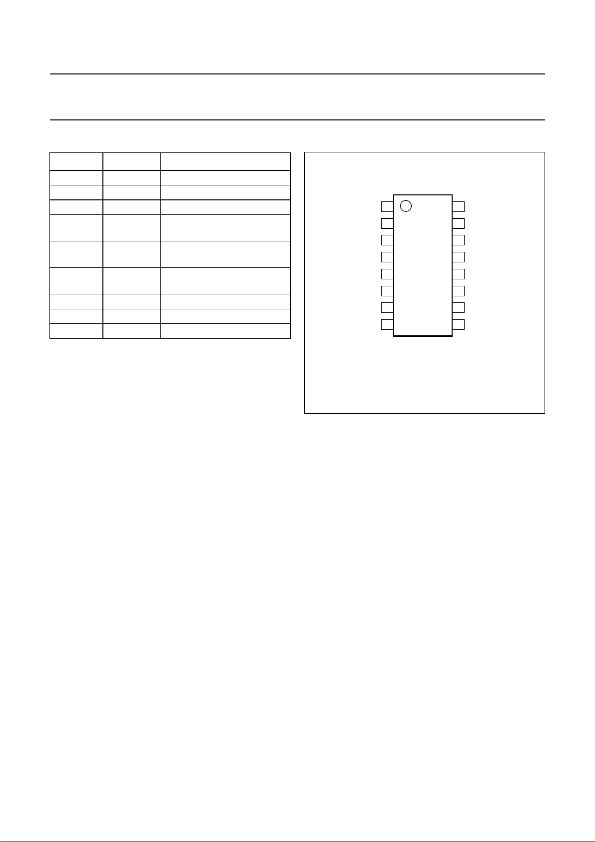
PINNING
SYMBOL PIN DESCRIPTION
n.c. 1, 16 not connected
V
CC
C
ext
LF 4, 13 leadframe connection
V
SS2
V
d
VM 11, 12 negative sense input
V
SS1
ST 15 status output
2 positive battery sense input
3 external delay capacitor
control circuit
5, 6 negative battery input and
power ground
7, 8, 9, 10 drain voltage of SW1 and
SW2
14 ground for the control circuit
handbook, halfpage
V
V
n.c.
V
C
SS2
SS2
CC
ext
LF
V
V
d
d
1
2
3
4
SAA1502ATS
5
6
7
8
MGM308
16
n.c.
15
ST
V
14
SS1
13
LF
12
VM
11
VM
V
10
d
V
9
d
FUNCTIONAL DESCRIPTION
Figure 3 gives the connection diagram of a Li-ion battery
pack. All that is contained within the solid perimeter is the
safety IC SAA1502ATS. It is a Multichip Module (MCM),
containing two separate but interconnected chips, one is
the control IC and the other contains two vertical power
NMOS transistors which are connected in anti series. Both
transistors have their backgate connected to their source,
resulting in two backgate diodes in anti series.
The basic function of the SAA1502ATS is to protect a
single Li-ion cell against overcharge and overdischarge for
reasons of lifetime and safety. The voltage across the cell
terminals is monitored continuously and compared to an
accurate internal reference voltage. For battery voltages
between 3.6 and 4.18 V and a (dis)charge current below
the current protection level, the safety unit is in normal
operating mode (see Fig.4). In this state both switches are
driven with an elevated supply voltage (with a charge
pump) which guarantees a low resistance in the main
current path. This is important for fully utilizing the high
energy density of Li-ion battery technology.
The discharge PowerMOS transistor SW2 is disabled to
block further discharge, when the battery is discharged
below 2.3 V. The battery voltage will increase stepwise,
because of the sudden disconnection of the load. The unit
will not re-enter the normal operation mode at this event
Fig.2 Pin configuration.
unless the battery voltage exceeds the voltage restarting
level of 3.6 V.
When no charger is present in the discharge inhibit mode,
the system will switch to the Power-down mode.
The current consumption of the unit (SAA1502ATS and
the Li-ion cell) is then reduced to a typical value of 0.1 µA
for minimizing the discharge of the battery pack.
Connecting a charger in the Power-down mode is detected
by a voltage difference between V
and VM of more than
CC
3 V. The system will then return to the discharge inhibit
mode. After a short transition phase characterized by
conduction of the backgate diode between the drain and
source leads of SW2, the system goes to the normal
operating mode and SW2 is powered again.
At zero voltage start-up, the system will start at the reset
mode. A special circuit keeps the charge transistor SW1
on as much as possible.
When the battery is charged to a voltage level of 4.18 V it
will enter the charge inhibit mode and the charge
PowerMOS transistor SW1 is switched off, disabling
charging. Connecting a load is then detected by the
reversal of the voltage across SW1 (I
> 1.5 mA) and will
dch
immediately reactivate SW1, entering the discharge
enable state.
1998 Jan 15 4

Philips Semiconductors Preliminary specification
Safety IC for Li-ion SAA1502ATS
A short time is needed to charge the gate of SW1. During
this time the backgate diode between drain and source of
SW1 conducts.
The system will remain in the discharge enable mode
unless:
• The battery voltage drops below 3.95 V, which results in
re-entering normal operation. This transition is not
externally noticeable, because both switches remain low
ohmic.
• A charger is connected which will immediately
deactivate SW1 if Ich> 280 mA. As an additional safety
precaution also VCC> 4.18 V yields the same reaction,
because a small current of a charger may be undetected
with the condition of Ich> 280 mA, leading to
overcharging the Li-ion cell.
Current protection will deactivate both switches and is
detected by a voltage drop or rise of VVM when both
switches are activated. A release of this state can only be
achieved by removing the load (or charger).
The temperature protection overrules all other states and
yields deactivation of both switches. This situation is
activated at a junction temperature of 130 °C and released
at a junction temperature of 60 °C. The temperature
protection is followed by a return to its preceding mode.
Normal mode
In case of correct temperature, battery voltage and
(dis)charge current, the system will be in the normal
operation mode. Both the charge and discharge output will
be active high, so both switches are conducting
(SW1 = SW2 = 1).
is charged at a voltage below 2.3 V, an extra condition of
V
> 2.3 V is included going from the discharge inhibit to
bat
the normal operation mode.
Power-down mode
At low battery voltage the supply current is reduced to
100 nA for minimizing the discharge of the battery by the
SAA1502ATS.
At the Power-down mode all analog circuitry, except
circuitry for detecting a charger present (V
− VVM> 3 V),
CC
is disabled. The Power-down mode is entered when the
system is in the discharge inhibit mode and no charger is
present. The discharge inhibit mode will be entered again
as soon as a charger is connected.
The detection of a charger is accomplished by detecting a
voltage difference of 3 V between V
and VM. In this
CC
mode the voltage difference (see Fig.5) is:
VCC− VVM=V
− VR1+V
bat
j(DO)+Vds(CO)
≈ V
bat
+ 0.6 V.
So in the application the battery has to be charged in the
Power-down mode until such a voltage that
VCC− VVM=3V.
Reset mode
If the battery voltage is below 1.9 V, the system will be in
the reset mode. Because in this mode the charge pump is
disabled and battery charging should be possible, the
charge FET is switched on with a reduced V
voltage.
gs
As soon as the battery voltage exceeds 2.25 V the system
will switch to the discharge inhibit mode and the charge
pump will be activated again.
Discharge inhibit mode
If the battery drops below 2.3 V, the system will switch to
the discharge inhibit mode. In this mode only charging of
the battery is allowed (SW1 = 1, SW2 = 0). The system will
return to the normal operation mode as soon as the battery
voltage will exceed 3.6 V, or by detection of a charge
current.
The overdischarge detection of 2.3 V has a delay of 40 ms
typical. The voltage detection level 3.6 V has a delay of
50 ms typical. Because a charge current is necessary to
increase the battery voltage, the system will normally
switch to the normal operation mode at V
= 2.3 V by
CC
detecting a charge current. But if the charge current is too
small to detect, the 3.6 V detection is a backup.
To prevent an instable situation between the normal
operation and the discharge inhibit mode when the battery
1998 Jan 15 5
Zero voltage start-up
The system has to be able to charge the battery at ‘0 Volt’.
This means that when connecting a charger in case of a
complete empty battery, the charge FET has to be active.
In the reset mode the charge FET (SW1) is connected via
a diode to V
, so that the charge FET will be active when
CC
the VVM voltage is negative. The discharge inhibit mode
will be entered as soon as a battery voltage exceeds
2.25 V.
Charge inhibit mode
If the battery voltage exceeds 4.18 V, the charge inhibit
mode will be entered. At this mode the battery can only be
discharged (SW1 = 0, SW2 = 1). The overcharge
detection has a delay of 40 ms. This delay can be
increased by an external capacitor. The delay time is then

Philips Semiconductors Preliminary specification
Safety IC for Li-ion SAA1502ATS
defined as:
td= 40 + (37 × C
) [ms], with C
ext
ext
in nF.
The system will return to the normal operation mode from
the charge inhibit mode when the battery voltage drops
below 3.95 V.
From the discharge enable mode the charge inhibit mode
will also be entered as soon as a charge current is
detected.
Discharge enable mode
When the system is in the charge inhibit mode, charging of
the battery is disabled because switch SW1 is turned off.
Discharge of the battery will then occur via the backgate
diode of SW1. So the output voltage will be approximately
0.6 V lower and also dissipation of the backgate diode of
SW1 occurs. It would be preferable to turn both switches
on at that time without allowing charging of the battery until
the battery voltage has dropped to 3.95 V.
If a discharge current larger than 1.5 mA is detected in the
charge inhibit mode, the system will activate the discharge
enable mode, activating both switches. From the
discharge enable mode the charge inhibit mode will be
re-entered as soon as a charge current is detected larger
than 280 mA or the battery voltage exceeds 4.18 V.
The detection of a higher voltage than 4.18 V is a backup.
If the battery is charged with a lower charge current than
280 mA, the system will not switch from the discharge
enable mode to the charge inhibit mode. Eventually, if the
battery is overcharged because of a small charge current,
the battery voltage will exceed 4.18 V and the system will
switch to the charge inhibit mode.
The system will return to the normal operation mode from
the discharge enable mode when the battery voltage drops
below 3.95 V.
If the system is in the charge inhibit mode, it will mostly go
to the normal mode via the discharge enable mode. But if
the system is in the charge inhibit state and the system is
stored for several years, the battery voltage can drop
because of the battery discharge by the SAA1502ATS and
the self-discharge of the battery. So a voltage drop of the
battery is possible, without detecting a discharge current.
Because of this, the normal operation mode should also be
entered from the charge inhibit state when the battery
voltage is below 3.95 V and not only from the discharge
enable mode. In this way, charging a battery is always
possible if the battery voltage is below 3.95 V.
Temperature protection
Internally the system will switch between the different
modes as given in the state diagram, independent of the
temperature. As the junction temperature exceeds 130 °C,
the output signals will be overruled and switched to zero
(SW1 = SW2 = 0).
The supply current will be reduced to approximately
100 nA when the Power-down or reset mode is activated.
In these modes the temperature protection is deactivated.
When the junction temperature drops below 60 °C, the
output signals will not be overruled any more.
Overcurrent protection
When the (dis)charge current exceeds the specified
maximum value, the current protection mode is entered.
An extra condition of SW1 = SW2 = 1 is necessary
because of the next situation:
If the system is in the discharge inhibit and a charge
current is detected (e.g. V
= −0.6 V) the normal
VM
operation mode will be entered. Because of a minimum
time in which the gate capacitors have to be charged, the
VVM voltage will be −0.6 V for a short period, when the
system is already in the normal operation mode. A V
VM
voltage of −0.6 V could also occur when the system is
charged with current exceeding the maximum charge
current. To prevent that a maximum charge current is
detected when coming from the discharge inhibit state, the
system waits until both SW1 and SW2 are fully charged
before a maximum (dis)charge current is detected.
So the voltages at SW1 and SW2 are measured to be sure
that the normal operation mode is stabilized before the
current protection mode can be entered.
The same applies when entering the discharge enable
state from the charge inhibit state by detecting a discharge
current.
The delay of the current protection as function of the
(dis)charge current is given in Fig.8.
1998 Jan 15 6
 Loading...