

Philips SAA1501T-N3 Datasheet

DATA SH EET
Objective specification
File under Integrated Circuits, IC11
December 1994
INTEGRATED CIRCUITS
Philips Semiconductors
SAA1501T
Battery charge level indicator

December 1994 2
Philips Semiconductors Objective specification
Battery charge level indicator SAA1501T
FEATURES
• High level of integration to allow assembly in intelligent
battery packs
• Accurate charge and discharge account
• Large dynamic range of charge and discharge currents
• Independent settings of charge and discharge efficiency
• 2 V minimum supply voltage (2 cell operation)
• Temperature protection of batteries during charging
• Temperature controlled self-discharge
• Accurate charge current regulation
• Two charge amount display modes, LCD and LED.
GENERAL DESCRIPTION
The SAA1501T is intended to be used as a battery monitor
and charge current control circuit in rechargeable battery
systems.
The SAA1501T is processed in BiCMOS technology
where the benefits of mixed bipolar and CMOS technology
is fully utilized to achieve high accuracy measurements
and digital signal processing in the same device. The
general function of the integrated circuit is a Coulomb
counter. During battery charging, the charge current and
charge time are registered in a Coulomb counter. During
discharge, the discharge current and time are recorded.
The momentary charge amount of the batteries can be
displayed either on an LCD screen or on an LED bargraph.
Using the SAA1501T, intelligent batteries or intelligent
battery powered systems can be easily designed with only
a few external components.
QUICK REFERENCE DATA
ORDERING INFORMATION
SYMBOL PARAMETER CONDITIONS MIN. TYP. MAX. UNIT
V
CC
supply voltage 2.0 3.0 4.3 V
I
CC
supply current VCC=3V;
Ic=Id=60µA
− 1.2 1.7 mA
I
CCstb
supply current in standby mode VCC=3 V;
V
CSI=VDSI
=0V
−− 100 µA
f
osc
fixed oscillator frequency C
osc
= 820 pF;
R
ref
= 51.5 kΩ
− 4.2 − kHz
V
i(s)
input sense voltage (pins 9 and 10) 0 − VCC− 1.6 V
T
amb
operating ambient temperature 0 − +70 °C
TYPE NUMBER
PACKAGE
NAME DESCRIPTION VERSION
SAA1501T SO24 plastic small outline package; 24 leads; body width 7.5 mm SOT137-1
December 1994 3
Philips Semiconductors Objective specification
Battery charge level indicator SAA1501T
BB
B
BBB
BB
B
BBB
BBBB
BBB
B
BBB
B
BBB
B
BBBB
BBB
BB
B
BB
B
BB
B
BBB
BB
B
BB
B
BB
B
BBB
BB
B
BB
B
BB
B
BBB
B
B
B
B
B
BBBBBB
B
BBBBBBB
B
B
B
B
B
B
B
B
B
B
B
B
B
B
B
B
B
B
B
B
B
B
B
BBB
B
BB
B
BBB
BB
B
BB
B
B
B
B
B
BB
B
B
B
B
B
B
B
B
B
B
B
B
B
B
B
B
B
B
B
B
B
B
B
B
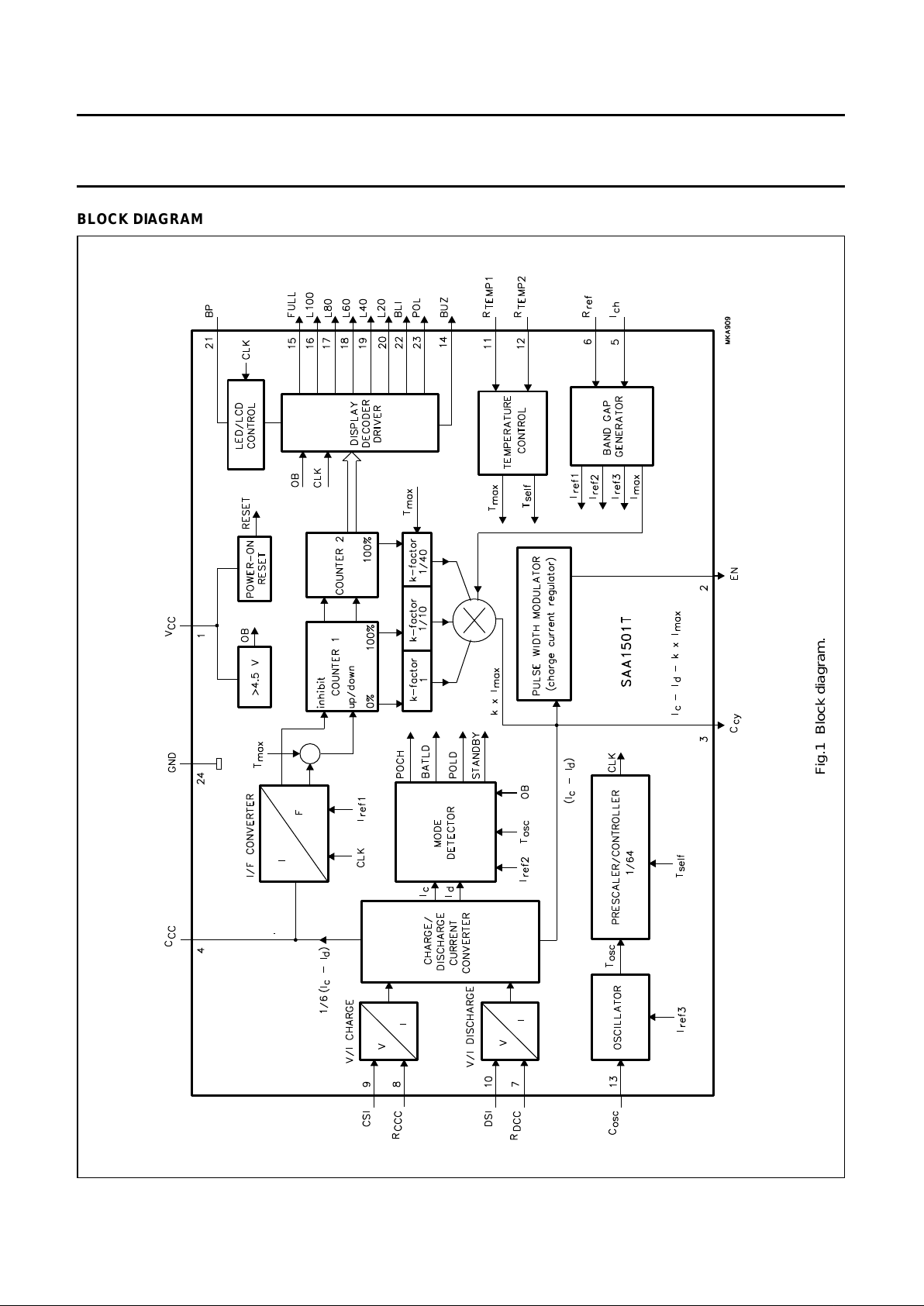
BLOCK DIAGRAM
Fig.1 Block diagram.
December 1994 4
Philips Semiconductors Objective specification
Battery charge level indicator SAA1501T
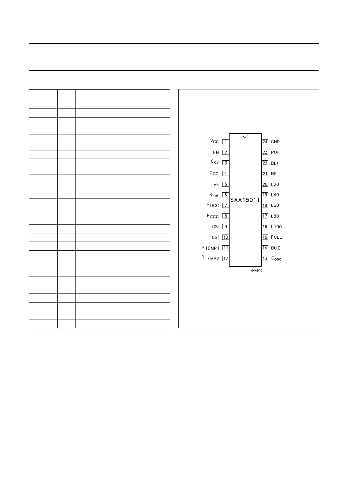
PINNING
SYMBOL PIN DESCRIPTION
V
CC
1 supply voltage
EN 2 enable output
C
cy
3 duty cycle capacitor output
C
CC
4 charge counter capacitor output
I
ch
5 maximum average charge current
setting input
R
ref
6 current reference resistor input
R
DCC
7 discharge current conversion resistor
input
R
CCC
8 charge current conversion resistor
input
CSI 9 charge sense input
DSI 10 discharge sense input
R
TEMP1
11 temperature sensing resistor 1 input
R
TEMP2
12 temperature sensing resistor2 input
C
osc
13 oscillator capacitor input
BUZ 14 buzzer output
FULL 15 battery full indication output
L100 16 100% segment indication output
L80 17 80% segment indication output
L60 18 60% segment indication output
L40 19 40% segment indication output
L20 20 20% segment indication output
BP 21 LCD back plane drive
BLI 22 battery low indicator LED output
POL 23 power-on LED output
GND 24 power ground
Fig.2 Pin configuration.

December 1994 5
Philips Semiconductors Objective specification
Battery charge level indicator SAA1501T
FUNCTIONAL DESCRIPTION
The most important function of the SAA1501T is the
charge account in rechargeable battery systems. Both
NiCd and NiMH batteries in all sizes can be used. The
system can operate alone as a charge monitor with a
charge amount display function or, can operate in
conjunction with a charger. If the SAA1501T operates
together with a charger, it delivers a control signal at output
EN, for charge current regulation or for battery voltage
regulation.
Fast charging systems and charge current regulation
The SAA1501T is especially designed to be used in fast
charging systems. In fast charging systems, the charge
time is lowered by raising the charge current. Signal EN
controls the charger current. The counters register the
state of charge of the batteries and at the 80% level the
charge current is reduced via a smaller duty cycle
regulation of signal EN. The second (slow) level fully
charges the batteries which is not possible with the first
(fast) level. After the slow charge mode the counter
switches over to an even smaller duty cycle of EN and thus
enters the third (trickle) charge mode, to overcome the
self-discharge of the batteries.
Current sensing and charge account
The charge current is sensed by means of a very low
resistance (e.g. 70 mΩ) sense resistor R
sc
(see Fig.8) to
save power at high charge rates. Via the V/I charge
converter and external resistor R
CCC
(see Fig.8), the
sensed voltage is converted into a charge current Ic (the
same is applicable for the discharge current). In the I/F
converter the charge current is converted into a frequency
for up-counting the counter. For the discharge current (Id)
the converted frequency is used for down-counting. The
up and down counting is registered in counters CNT1 and
CNT2, depending on the actual charge and discharge
current levels of the batteries. This is called dynamic
charge account.
Charge display
The charge amount represented by the Coulomb counter
can be displayed via an LCD screen or via an LED
bargraph. If the charge amount is reduced to 0%, the
battery low indicator (BLI) LED is turned on at the end of a
battery discharge session. A flashing BLI, in combination
with a repeating buzzer alarm, informs the user about the
low charge state. A new charge session should then be
started.
Protections
In the temperature control block, the absolute temperature
is used as a protection to end the fast charge cycle. Fast
charging at high temperature is not permitted because of
degradation of the battery cells. If the batteries are
disconnected, an open-battery condition is recognized and
the SAA1501T enters the standby mode.
Mode detection
The mode detector detects whether there are any charge
or discharge currents, whether the system is powered,
whether loads are connected or whether the system is in
the standby mode. If power is connected, the power-on
LED (POL) is on. In the standby mode, the Coulomb
counter will count down in accordance with the
self-discharge speed of the batteries, which is temperature
controlled. The following subsections describe the various
blocks of the block diagram in more detail.
Supply and reference
During the period when VCC rises from 0 V to the internal
reset level, all counters are reset. The internal reset is
released before VCC reaches 1.7 V. The operating supply
voltage ranges from 2 V to the open battery level of
4.3 V (min). The characteristics are guaranteed at
VCC= 3 V. In order to protect the SAA1501T against high
supply voltages during open battery in a flyback converter,
a voltage clamp circuit is made active at 6.35 V (typ). The
clamping current must not exceed 80 mA. A band gap
reference block is included to generate accurate voltages
i.e. for the oscillator. Moreover, together with R
ref
, accurate
currents are generated which are used in the I/F and V/I
converters and the oscillator block. In the standby mode
only the oscillator and the digital parts are active to limit the
discharge current of the batteries to a current level of less
than 100 mA. The circuits that are needed temporarily are
switched on and off during standby (see “Timing
characteristics” t
som
).
Voltage-to-current charge and discharge
In the V/I converter, the input charge current is translated
into acceptable levels for the circuit. The conversion
formula is:
; where R
CCC>Rsc
(see Fig.7)I
c
I
ch earg
Rsc×()
R
CCC
---------------------------------------
=

December 1994 6
Philips Semiconductors Objective specification
Battery charge level indicator SAA1501T
With R
CCC
, the charge efficiency can be manipulated
depending on the charge level. The restriction of the
SAA1501T is a maximum average charge current of 60 µA
and a minimum momentary charge current of 0.6 µA. The
same formula is applicable for the discharge current. The
discharge efficiency can now also be changed by R
DCC
depending on the discharge current levels, but
independent of the charge current. As both sense levels
are referenced to ground, the sensing elements could be
combined into one. The outputs are used combined as
1
⁄6× (Ic− Id) in the I/F converter and combined as (Ic− Id)
in the pulse width modulator block and made separately
available in the mode detector. The conversion is made
lower by a factor of 6 in the I/F converter block, thereby
enabling the use of poor leakage capacitors on pin 4. All
V/I converter pins are sensitive to capacitive loading
(C
out
× R
conv
< 1 ms), the conversion resistors should be
mounted as close as possible to the output pins.
I/F converter
This block produces up-counts while charging and
down-counts while discharging. The I/F converter
translates the charge/discharge currents into a frequency.
This frequency is determined by
During the time period ‘t’, the charge current, expressed as
a ‘Charge Parcel’, will be counted in the Coulomb counters
(CNT1 and CNT2). During discharge the ‘Charge Parcel’ is
the product of the discharge current and the ‘t’ from the I/F
converter generated frequency. The momentary contents
of the Coulomb counter is a multiple of the ‘Charge
Parcels’.
Coulomb counters CNT1 and CNT2
The SAA1501T has been designed for average maximum
charge and discharge current levels of 5 C and minimum
charge and discharge current levels of 0.05 C. This means
that counter CNT1 will be full, or empty, after a minimum
time period of 12 minutes at maximum charge and
discharge currents at the recommended oscillator
frequency. Higher charge and discharge rates than 5 C
are possible, but only by changing the oscillator frequency.
It should be noted that the self-discharge time and the
display functions are influenced by a higher oscillator
frequency. The SAA1501T enables top-up charging in
order to account for the decrease of charge efficiency at
high charge rates. The SAA1501T switches to the slow
charge mode at full recognition when CNT1 is at its
maximum. As soon as the batteries are completely full
(when CNT2 is at its maximum), the SAA1501T switches
f
I(
cd()Rsense
6 )××
C(
CC
∆V
oscRCCC RDCC()
)××
----------------------------------------------------------------------------------- -
=
to the trickle charge mode to overcome the self-discharge
of the batteries. The top-up charge volume of
CNT2 = 0.2 × CNT1 = 0.2 C (where Q is rated as Ampere
hours of the battery). The slow and trickle charge current
levels are dependent on the k-factor. Signal EN controls
the external charger e.g. TEA1400 (see Fig.8). When an
LED bargraph display is used, the LED currents are also
considered as a battery discharge current, and therefore
influence the duty cycle of the charge current regulation
signal EN. The SAA1501T also enables temperature
protection. In the event that the battery temperature
exceeds a certain maximum temperature level
(T
battery>Tmax
), which can be set by an external NTC
resistor, the SAA1501T switches to the slow charge mode.
In the standby mode (self-discharge mode), which is
recognized by the SAA1501T in the mode detector when
both the charge and discharge currents are zero
(Ic=Id= 0), the self-discharge of the batteries is registered
by counting down in 200 days (based on f
osc
= 4 kHz) if
T
battery<Tself
or in 100 days (based on f
osc
= 4 kHz) if
T
battery>Tself
. T
self
is also set by means of an external NTC
resistor.
Band gap generation
From the band gap voltage block, two reference voltages
are derived V
ref
and V
max
. Voltage V
ref
at pin R
ref
sets the
reference currents, I
ref1
(I/F converter); I
ref2
(mode
detector) and I
ref3
(oscillator). Voltage V
max
sets the
current I
max
which is used in the pulse width modulation
block to accurately control the charge current.
Charge current regulation
While charging, the SAA1501T produces a charge current
regulation signal EN in the pulse width modulation block
which is used for controlling an external charger. This
digital signal EN is derived from the signal produced at pin
C
cy
. The duty cycle is determined by
in which the value of k depends on the state of the
counters CNT1 and CNT2:
CNT1 is not full; k = 1 (fast charging).
CNT1 is full; CNT2 is not full; k = 0.1 (slow charging).
CNT1 and CNT2 are full; k = 0.025 (trickle charging).
δ
kI
max
×
I
cId
–
------------------- -
=
 Loading...