


HT RM 310
TM
HITAG
Revision 2.3
Mini Reader Module
November 1997Preliminary Specification

02-10-1998 Rev. 2.3
HT RM310
Contents:
1. Introduction.................................................................................................................4
1.1. Features of the Reader Module HT RM310....................................................................4
1.2. System Structure............................................................................................................5
2. Technical Data............................................................................................................6
2.1. General Data ..................................................................................................................6
2.2. Dimensions of the HT RM310........................................................................................6
2.3. Pin Assignment of the Male Connector...........................................................................7
2.4. How to Design Proximity Antennas................................................................................8
2.4.1. Basics.................................................................................................................8
2.4.2. Antenna Coil ......................................................................................................9
2.4.3. Measuring Inductance.......................................................................................10
2.4.4. Antenna Tuning................................................................................................10
2.4.5. Determining the Serial Resistance of the Antenna..............................................11
2.4.6. Checking the Antenna Voltage ÛL.................................................................... 11
2.4.7. Procedure for Practical Antenna Design............................................................12
3. Interface HT RM310
⇔ Host ....................................................................................14
3.1. General Definitions....................................................................................................... 14
3.1.1. Hardware .........................................................................................................14
3.1.2. Structure of the Protocol..................................................................................15
3.2. Set of Commands .........................................................................................................16
3.2.1. HITAG 1 Read/Write Commands.....................................................................16
3.2.2. HITAG 2 Read/Write Commands.....................................................................16
3.2.3. Public Modes....................................................................................................16
3.2.4. General Commands...........................................................................................17
3.2.5. Commands for Personalization..........................................................................17
3.3. Description of the Commands.......................................................................................18
3.3.1. GetSnr_HT1.....................................................................................................18
3.3.2. GetSnr_HT1_Adv ............................................................................................18
3.3.3. SelectSnr_HT1.................................................................................................19
3.3.4. SelectLastSnr_HT1 ..........................................................................................19
3.3.5. HaltSelected_HT1............................................................................................20
3.3.6. ReadPage_HT1_P / ReadPage_HT1_C ............................................................20
3.3.7. ReadBlock_HT1_P / ReadBlock_HT1_C.........................................................21
3.3.8. WritePage_HT1_P / WritePage_HT1_C...........................................................22
3.3.9. WriteBlock_HT1_P / Write Block_HT1_C.......................................................23
3.3.10. MutualAuthent_HT1 ......................................................................................24
3.3.11. GetSnr_HT2_P...............................................................................................25
3.3.12. GetSnr_HT2_C ..............................................................................................26
3.3.13. HaltSelected_HT2..........................................................................................27
3.3.14. ReadPage_HT2 ..............................................................................................27
3.3.15. ReadPageInv_HT2 .........................................................................................28
Page 2 of 41 Htrm310.doc/HS

HT RM310
Rev. 2.3 02-10-1998
3.3.16. WritePage_HT2..............................................................................................28
3.3.17. ReadPublic A..................................................................................................29
3.3.18. ReadPublic B..................................................................................................29
3.3.19. HF-OFF..........................................................................................................30
3.3.20. Powerdown....................................................................................................30
3.3.21. GetVersion.....................................................................................................30
3.3.22. WriteSecret_HT .............................................................................................31
4. Appendix A: Timing Interface.................................................................................34
5. Appendix B: Application Example.........................................................................35
6. Appendix C: Reaction Times of the Reader Module ............................................36
7. Appendix D: List of Command Bytes....................................................................37
8. Appendix E: List of Status Bytes...........................................................................38
9. Appendix F: List of KEYS in the Crypto Processor..............................................40
HITAG™ is a trademark of Philips Electronics N.V.
Htrm310.doc/HS Page 3 of 41

02-10-1998 Rev. 2.3
HT RM310
1. Introduction
1.1. Features of the Reader Module HT RM310
The reader module HT RM310 was designed for reading HITAG 1 and HITAG 2 transponders. It
allows universal and cost efficient communication with transponders on a very basic system level.
Thanks to the small size of the module it can be easily integrated and used in various applications.
The interface to the host is designed in a rather simple way. It allows fast communication between
reader module and transponder, while the user need not take into account analogue signals or the
timing of the transponder.
The reader module HT RM310 is suited for all applications requiring prox imit y op er a t ing r a nge s.
By using only a few external components the reader can be easily adapted to a specific read/write
device which can be used in various applications.
The reader module HT RM310 has an integrated crypto processor which allows data encryption.
The HT RM310 supports the following operating modes:
• HITAG 1 (Plain and Crypto Access)
• HITAG 2 Crypto Mode
• HITAG 2 Password Mode
• HITAG 2 Public Mode A (Standard Read Only transponders structured like a µEM H400x)
• HITAG 2 Public Mode B (Transponders accor ding to ISO Standard 11784 and 11785 for ani-
mal identification)
Page 4 of 41 Htrm310.doc/HS
HT RM310
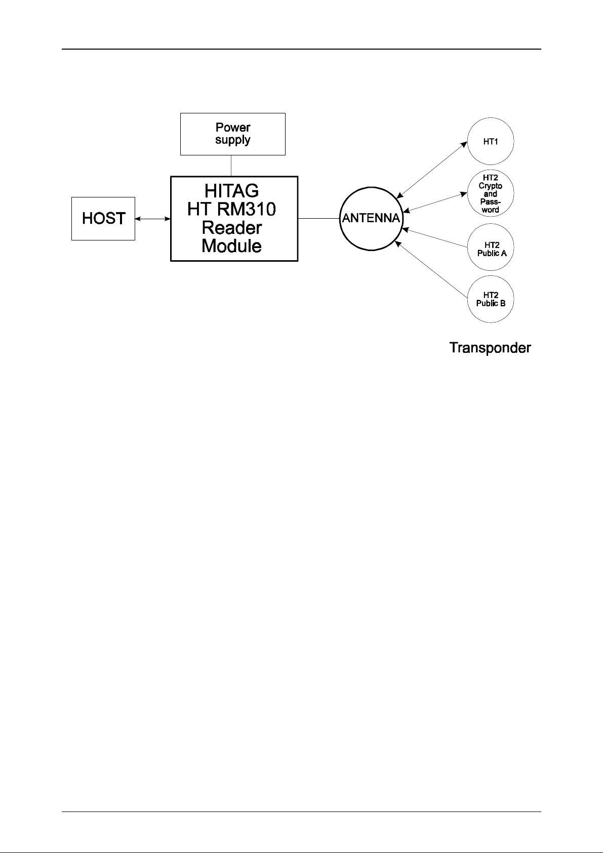
1.2. System Structure
Rev. 2.3 02-10-1998
The components shown in the diagram above are required in order to create a complete system
with the HT RM310 reader module.
Antennas of different shapes can be connected to t he module. The antennas are tuned using a capacitance and optionally a resistor. For detailed information please see Chapter 2.4.
The host system controls all actions of the reader module via a parallel interface.
The supply voltage must be a stabilized 5V DC voltage.
Htrm310.doc/HS Page 5 of 41

02-10-1998 Rev. 2.3
2. Technical Data
2.1. General Data
HT RM310
Dimensions ( L x W x H)
Supply voltage
Power consumption:
• standard mode
• energy saving mode
Temperature range
47.3 x 28.3 x 11.4mm
5 V DC ± 5 %
(depends on the geometry of the antenna)
typ. 290 mW
20 mW
-25°C to +70 °C in operation
-40°C to +85°C when stored
Antenna
Interface
can be connected via the pin connectors
CMOS
8 Bit parallel + 2 control lines
EEPROM
10,000 write cycles
(HT RM310 only)
2.2. Dimensions of the HT RM310
15
1
16.5mm
RM2.54
47.3mm
14.7
3.3
8
25.4mm
7
28.3mm
Page 6 of 41 Htrm310.doc/HS

HT RM310
Rev. 2.3 02-10-1998
2.3. Pin Assignment of the Male Connector
The male connector is divided into two lines. For the pin numbers please refer to the diagram
"Dimensions of the HT RM310".
Pin Number Name Function
1 /HCDA
2 /RCDA
3 /MCLR
Control signal Host data control
Control signal Reader data control
Reset entry: A reset has to be performed in case
of a voltage drop. Without this precaution, the
internal crypto unit might get irreversible damaged.
(refer to Appendix B)
4 VCC
5 GND
6 RxA
7 TxA
8D7
9D6
10 D5
11 D4
12 D3
5 V Supply voltage *
Ground
Antenna - input signal
Antenna - output signal
Data Bit 7
Data Bit 6
Data Bit 5
Data Bit 4
Data Bit 3
13 D2
14 D1
15 D0
* Only regulated voltage to be used
Data Bit 2
Data Bit 1
Data Bit 0
Htrm310.doc/HS Page 7 of 41
02-10-1998 Rev. 2.3
HT RM310
2.4. How to Design Proximity Antennas
The antenna is an import ant part in the data transmission between the read/write device and the
t ra nsp o nd er . T hu s, whe n build ing th e ant e nna th e ins tr u ct io ns s ho uld be st r ict ly fo llo we d in o r de r
to achieve optimum results.
When deciding upon the size of the antenna the ratio between the diameter of the antenna and the
diameter o f the tra nspo nder´s c oil is fundament al. T his ra tio sho uld be within t he limits ranging
from 1 to 4. If the ratio is too big or t oo small, read/write distances may decrease and difficulties
during data transmission may occur.
2.4.1. Basics
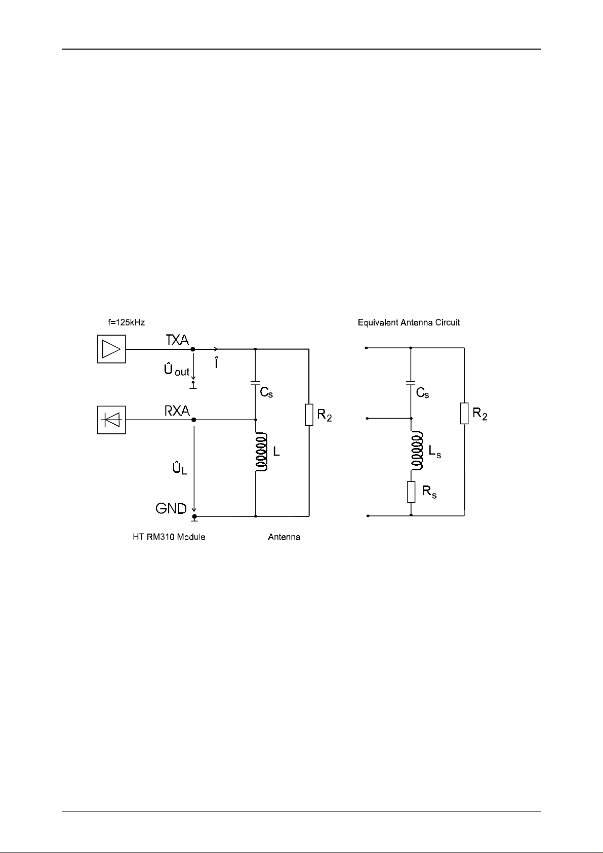
Th e fo llow ing blo c k dia gr am sh ow s t he g ene ral s tr uc tu re of a pr ox imity a nte nna and its co nne ction to the proximity read/write device.
Whe n de velo p ing an a nt enn a it is imp o rt a nt t o ta ke int o co ns ide r at io n t he limits o f t he r ea d/ w rit e
device, i.e. the maximum antenna current and the maximum voltage at the receiver input (Pin
RxA). With an output vo ltage Û
(Pin T xA ) of appr oxima tely 2 . 5Vp the follow in g limits a pply to
out
the reader module.
Maximum antenna current ( Î ) : 100 mAp
Maximum input voltage (Pin RxA, ÛL) : 32 Vp
The resistance R2 (approx. 600 ... 1000 Ω) is only needed with cables longer than 50 cm.
Page 8 of 41 Htrm310.doc/HS

HT RM310
Rev. 2.3 02-10-1998
2.4.2. Antenna Coil
The inductance of the coil should be in the range of 350 and 500 µH.
The quality factor of the antenna should be approximately Q = 40.
fL
⋅⋅⋅2
Q
π
=
If the Q factor is too high, it must be reduced by using an additional resistor. Generally speaking it
is better to have a smaller diameter of the wire for the coil rather than using an additional resistor.
The following equation shows the approximate calculation of the number of co il windings for a
required inductance and antenna geometry:
=⋅⋅ −
La
219ln
D
R
S
a
S
.
⋅
KN
The abbreviations read as follows:
L required inductance (nH)
a circumference of the antenna (cm)
D diameter of the wire (cm)
N number of windings
K geometrical constant
circle antenna: K= 1.01
square antenna: K= 1.47
Please note:
The factor K is usually much smaller than the quotient a/D and can thus be neglected.
N
.
≈
L
aaD
⋅⋅219ln( )
Htrm310.doc/HS Page 9 of 41
02-10-1998 Rev. 2.3
HT RM310
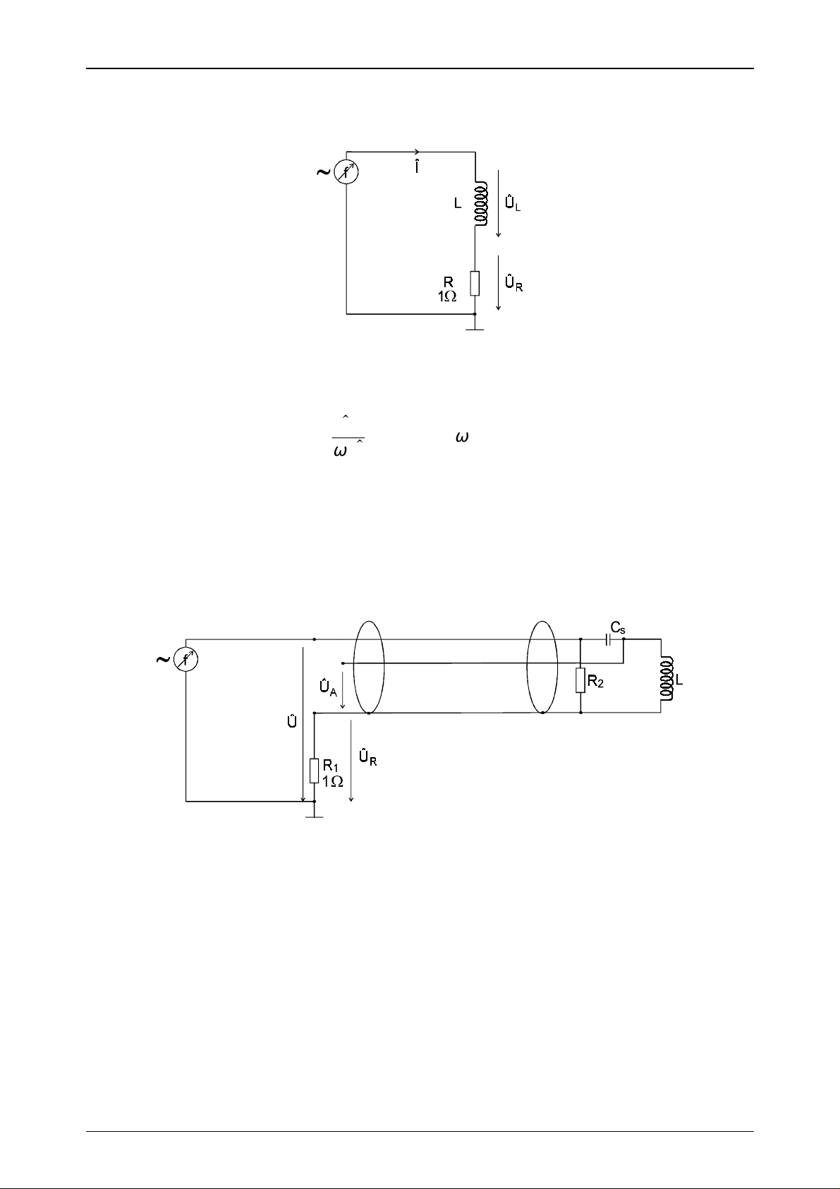
2.4.3. Measuring Inductance
The inductance of the designed coil can be determined using the following measuring procedure.
A sinus signal of 125 kHz is supplied by using a function generator. If you measure the current Î
and the antenna voltage ÛL, the inductance can be calculated according to the following formula:
U
L
L
=
I
⋅
ω
ωπ
=⋅⋅2 f
2.4.4. Antenna Tuning
The antenna has to be tuned to its final form by using the connecting cable. You must not change
anything with the antenna coil or with the connecting cable, after having finished tuning the ant e nn a . If yo u d o, t h e me c ha n ic a l c hange s w ill influenc e th e e le ctrica l v a lu e s a n d the a nten n a w ill be
detuned again.
A sinus signal of 125 kHz is fed to t he antenna connectors using a frequency generator. Now you
measure the voltages Û and ÛR wit h an os cillo sco pe . T hen c han ge t he freq ue ncy u ntil Û and Û
are in phase.
R
If the resonance frequency achieved is too high, CS has t o b e in cr e a se d . I f it is t oo lo w , CS has t o
be decreased.
The aim is to arrive at a resonance frequency of 125 kHz using CS.
The phase of impedance has to be in the range of +/- 10°.
Page 10 of 41 Htrm310.doc/HS
HT RM310
Rev. 2.3 02-10-1998
2.4.5. Determining the Serial Resistance of the Antenna
Use an oscilloscope to measure ÛA and ÛR at a frequency of 125 kHz.
The serial resistance RS can be calculated with the following formula:
U
R
I
=
R
1
⇒ R
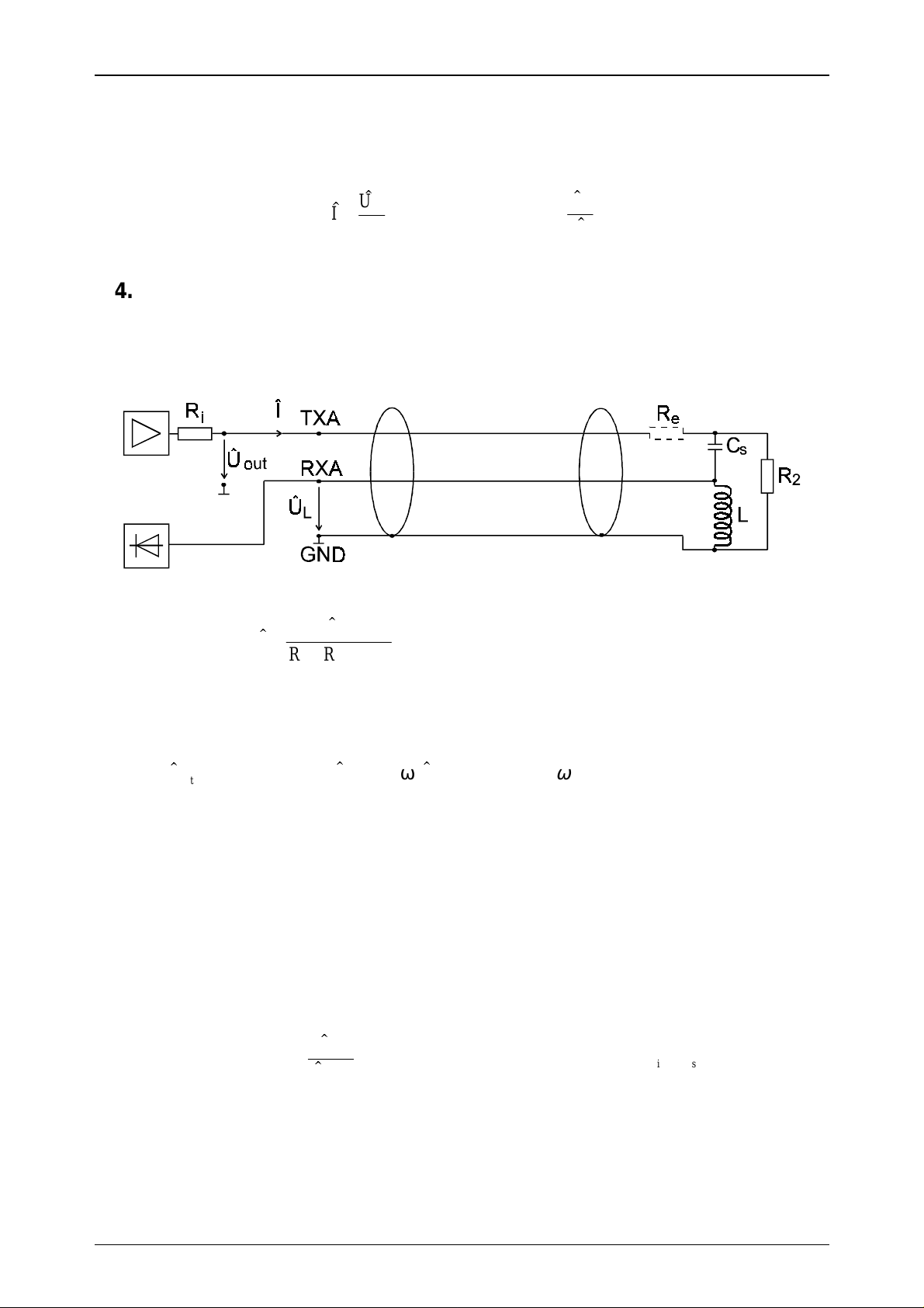
2.4.6. Checking the Antenna Voltage Û
L
U
A
=
S
I
Before connecting the antenna to the read/write device (as shown in the gr aph below), you must
carry out a check calculation of the input level of the read/write device according to the formula
below in order to prevent damage.
U
I
=
RR R
out
++
is e
()
with Ri≈ 22Ω
(Ri is the internal resistance of the output amplifier)
out
≈ 25
.UVp
UL I
=⋅⋅ω
L
ωπ
=⋅⋅2 ff kHz=125
Th e ma ximu m va lu e for ÛL is 32 Vp. Based on this calculation damage is avoided at the receiver
input (Pin RxA) of the read/write device.
With ÛL < 32 Vp the resistor Re can be omitted.
With ÛL > 32 Vp you have to calculate and insert Re according to the following formula:
U
RL
=⋅⋅ − −
e
ω
U
out
L
max
RR
is
⇒
RL RR
≥⋅⋅ − −
ω
eis
0 078,
with Ri≈ 22Ω
Htrm310.doc/HS Page 11 of 41

02-10-1998 Rev. 2.3
HT RM310
2.4.7. Procedure for Practical Antenna Design
The procedure how to design a HITAG Proximity antenna has been described in the previous
chapters. Generally speaking the following steps have to be considered:
1. The required antenna inductance can be chosen in the range of 350µH and 500µH
(e.g. L=420µH).
2. The number of turns N can be calculated with the following formula:
LnH
N
.
=
219ln ( )
for L=420µH:
N
=
19
.
420000
⋅⋅⋅ −
aaDK aaD
2
ln ( ) ln( )
Please note:
Usually the factor K is much smaller than the quotient from a/D and can thus be neglected.
3. No w the antenna can be build according to t he required dimensio ns (circumference a) with the
calculated number of turns.
Please note:
The antenna coil must not be changed afterwards because with the mechanical dimensio ns the
electrical specifications are changing, too. That means the number of turns, the shape, the arrangement of the coil windings and the antenna supply cable must be used in their final form.
Please note:
Metal influences considerably the electric characteristics of the antenna. If metal is close to t he
antenna when it is set up, all instructions below must be followed (distance from
metal < maximum diameter of the antenna).
4. Measuring the inductance L of the antenna is described in Chapter 2.4.3.
5. Determination of the serial capacitor CS is described in Chapter 2.4.4.
Please note:
The capacitance of the antenna supply cable can be determined according to the specifications
given in the data sheet of the cable (e.g. Cp = 180 pF/m).
6. Now the antenna has to be tuned according to the instructions given in Chapter 2.4.4.
The tuning of the antenna is finished when the phase of impedance is within the range of
+/- 10°.
7. The serial resistance Rs of the antenna is the impedance of the tuned antenna and is an ohms
resistance at the resonance frequency ( f=125 kHz). It can be calculated acco rding t o the formula given in Chapter 2.4.5.
[]
⋅⋅⋅ −
aaDK
19
633
.
⋅
=
Page 12 of 41 Htrm310.doc/HS

HT RM310
Rev. 2.3 02-10-1998
8. In order to achieve a satisfactory reading distance, the quality factor of the antenna coil (for
non-metal environment) should be approximately Q = 40.
The quality factor of the coil is calculated as follows:
Q
L
⋅
ωπ
=
=
R
SS
⋅⋅⋅
2
R
fL
9. By knowing Rs and the dropping resist or (Ri = 22Ω) the current Î and the antenna voltage Û
can be calculated. It is very import ant to calculate t he antenna voltage before connecting the
antenna to the HT RM310 module to avoid damage. If the calculated value of ÛL is higher than
ÛL =32 Vp, a resistor Re must be used to protect the receiver input.
The resistor has to be placed as shown in Chapter 2.4.6.
10. After having checked the antenna voltage as described in point 9, connect your antenna to t he
HT RM310 mo dule and measure the read/write distances with your transponders. Should the
read/write distances not meet your expectations, the following points should be considered:
L
The size of the antenna and the size of the transponder have to be in a defined ratio (between
•
4 and 1).
That means if you increase the antenna beyo nd a certain size, t he maximum read/write distances will decrease when using the same transponder.
The optimal shape of the antenna coil is a circle, while the performance of a square shaped
•
coil is much better than that of a rectangular one (with the same circumference).
In order t o achieve better r ead/write distances the quality fact or of the antenna coil should
•
be increased, but must not be higher than Q=40. This can be attained with the following
measures:
All conducting material has to be removed from the antenna environment.
−
A thicker wire can be used for the coil.
−
Ferrite can be placed behind the antenna coil to concentrate the field.
−
Extension of the antenna area.
−
Also with a different number of turns better results can be achieved.
−
Attention:
The above measures must not differ from the antenna design instructions of Chapter 2.4.
Htrm310.doc/HS Page 13 of 41
 Loading...