

Page 1

Philips Medical Systems DMC GmbH
Replacement kit
for rel. 2 generators
9890 000 61323
Rotor Control HS
SERVICE MANUAL
742
UNIT
File this documentation in manual: OPTIMUS section 8 “SERVICE INFORMATION”
DMC Hamburg
Printed in Hamburg, Federal Republic of Germany
E
2003 Philips Medical Systems
ALL RIGHTS RESERVED
4512 984 22433 REV AA 1
titel _repl_roc o
Page 2

SERVICE MANUAL -- UNIT
Replacement kit Rotor Control HS Rel. 2
Replacement kit Rotor Control HS
for rel. 2 generators
Type No: 9890 000 61323
In case there are any questions concerning this manual,
please send this LOPAD via fax to 49/(0)40/5078 2481
File: RK_RoCo_HS_rel2_22433AA
Author: Th. Frenschek
List of pages and drawings (LOPAD) Manual Order No: 4512 984 22433
released: 10/2003
1
2
3...7 (03.0)
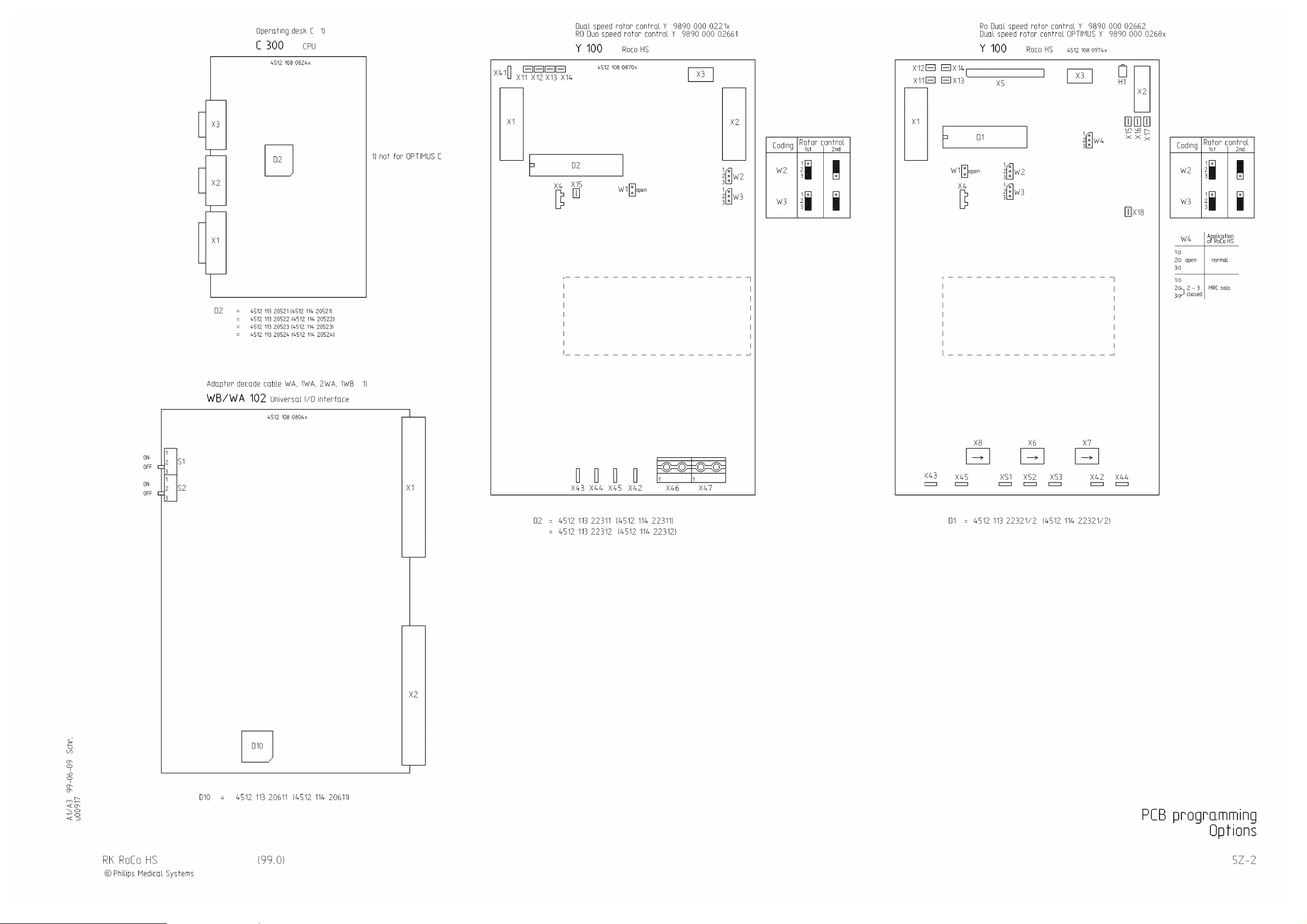
Z1-13.2 (c/00.0) A3 RK RoCo HS
5Z--2 (99.0) A3 RK RoCo HS
_____________________________
2
E
2003 Philips Medical Systems
ALL RIGHTS RESERVED
4512 984 22433 REV AA
rk_roc o_HS_rel2_22433_l opad
Page 3

Replacement kit rotor control HS rel. 2
1. Introduction
This document describes the detailed replacement procedure for the rotor control unit.
Additional stator inductance measurements are described to detect stator inductance problems which can lead to
rotor control failures.
2. Compatibility
Rotor control HS 9890 000 02212 4512 104 71401/2/3/4/5
OPTIMUS RAD 9890 000 02001 release ≤ 2.x
3. Scope of delivery
Rotor control HS unit replacement kit 9890 000 6132x
comprising
-- Rotor control HS 4512 104 7410x
including software 4512 1 13 22341
-- This manual 4512 984 22433AA
4. Tools
-- Standard tool set
-- Service PC with XRGScope
-- Inductivity measuring device to be obtained locally
or to be ordered at SL Hamburg (4512 101 77141)
5. Service reliability information
Permanently interested in quality improvement of the PMS products, we depend on information from the field.
Therefore, please send us the current generator logfile information.
Please download the generator errorlog logfile.
The filename must express the generator serial number and generator release.
e.g. ”23960234.tdl” for Rel. 2.3 and serial number 960234.
Send this file to:
Carsten Mais, Test & Integration Generators, PMS Hamburg,
as attachment to E-Mail.
E-Mail:
Carsten.Mais@philips.com
RK RoCo HS rel.2 (03.0) 3
rk_roc o_HS_rel2_030
E
2003 Philips Medical Systems
ALL RIGHTS RESERVED
Page 4

Replacement kit rotor control HS rel. 2
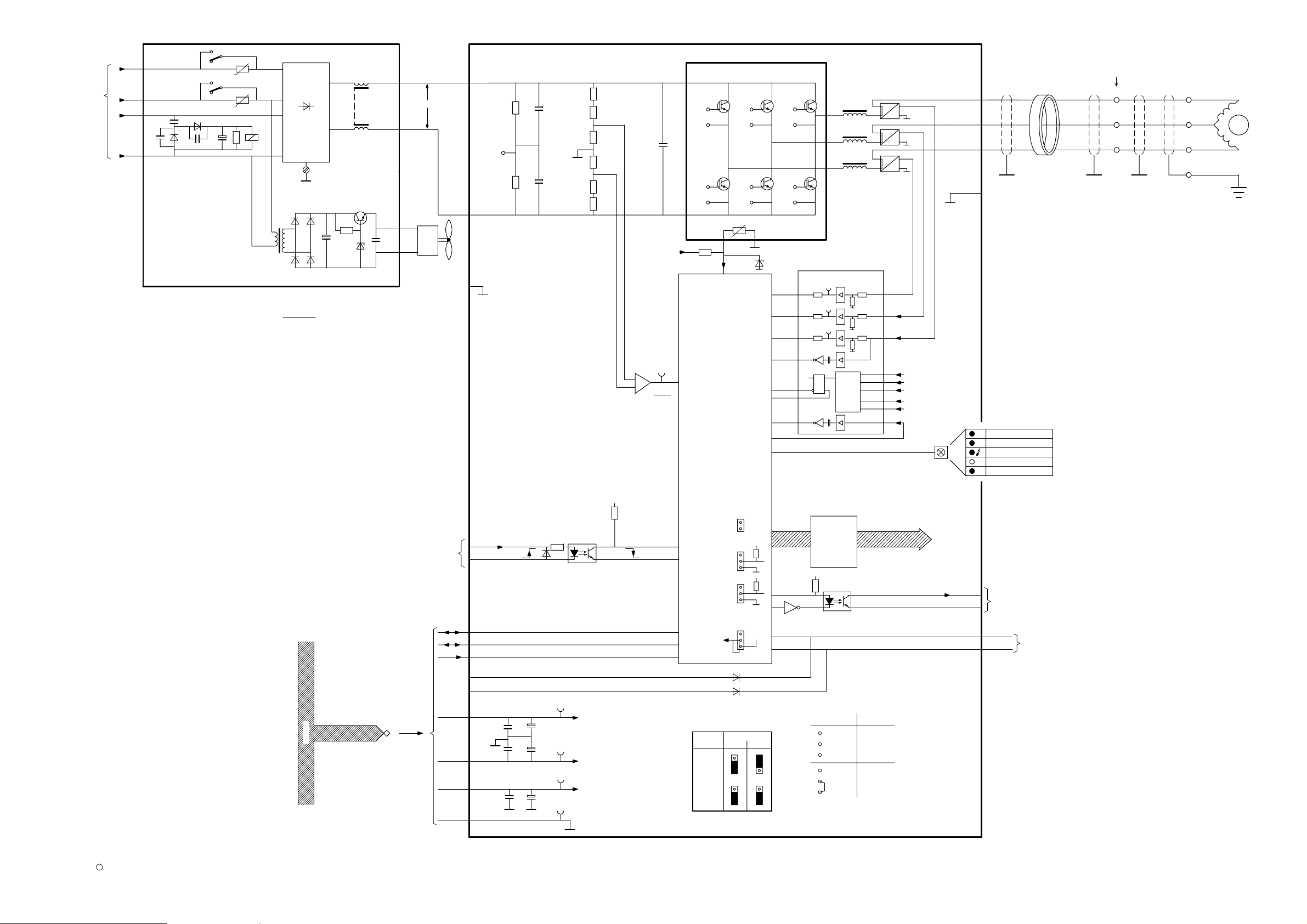
6. Stator inductance test
This test is suitable to detect internal stator coil shortcircuits.
Depending on the location of a possible shortcircuit (number of shorted wires), the resistance of the coil still shows
a value within tolerance but the inductivity is out of tolerance. This leads to an increased stator current and can
destroy the rotor control unit.
SRO-Stator
(mH)
101 202
U
stator link wire
--10% +10%
U--V 101/103 –
= 1–2 
51,7 57 62,7
SRO/RO
107/109
V--W208/210 –
202/204
= 2–3 
30,6 34 37,4
V
W
109 210
-- Stator links not removed.
-- Stator wires U--V--W disconnected.
This check can be performed with a low--cost inductance measuring device to be obtained locally or to be ordered
at the SL Hamburg with the 12NC 4512 101 77141.
Please send the measuring results including the tube type and serial number together with generator serial number
and customer/site data to:
Dietmar Morgenstern Service Innovation
Tubes
Email: dietmar.morgenstern@philips.com
or to
Help Xray Hamburg
Email: Helpdesk.Xray
.Hamburg@philips.com
.
.
e.g.
XYZ hospital, Town, Country
SRO 25 50 serial number 89123 – 654123
Generator Optimus 50 970023
Inductance:
U--V = 56; V--W = 35
Appreciate your help and many thanks in advance.
E
2003 Philips Medical Systems
ALL RIGHTS RESERVED
RK RoCo HS rel.2(03.0)4
rk_roc o_HS_rel2_030
Page 5

Replacement kit rotor control HS rel. 2
7. Replacement procedure
Caution
Switch the generator off and disconnect it completely from mains with earth-leackage breaker or mains
switch!
7.1. Remove old RoCo unit
S Remove the data cable from back panel EZX 51 and leave it with the old RoCo unit.
S Disconnect the stator wires from the terminal EX 1100 (single tube generator).
In case Tube switch unit EWG is present:
S Remove plug EY 100 X3, it will be used again
later.
S Disconnect stator cable Y100 – EWG at EWG K11:1 :2 :3 and leave it with the old RoCo unit.
S Remove the mains wires from ENF3: T1 :T2 :T3 and ENX 1102 and leave them with the old RoCo unit.
S Remove the RoCo unit completely from the
generator.
7.2. Install the new RoCo unit
S Install the new unit into the generator.
S Connect the mains wires at ENF3: T1 :T2 :T3 and ground wire to ENX 1102.
S In case Tube switch unit EWG is present:
S Establish stator cable of RoCo unit at EWG K11: 1 :2 :3.
S Reestablish plug EY 100 X3.
Single tube generator
S Connect the stator cable to the terminal EX 1100 (U-V-W) and cable of RoCo unit likewise.
Make sure the screen of the stator cable is properly connected to ground.
S Relieve the tension on the stator cable with a cable tie.
EX1100
Note
-- Use screened cables. Connect the screen to
earth at both ends. (0722 215 02054)
-- Do not mix up the phases, otherwise
components of the rotor control may be
destroyed.
UVW
cable tie
terminal
rotor control
S Connect the data cable at EZX51.
for screen
tube
S Tighten all cables and wires with cable ties.
S Check that the start up and brake function of the tube works normal.
In case rotation prolongation is programmed: Once started with PREP, the anode keeps rotating for 30 s after
the last let go of the PREP position as long as no exposure has been switched. The tube finally stops if an
exposure has been switched or after 30 s or if any of the desk buttons have been activated.
RK RoCo HS rel.2 (03.0) 5
rk_roc o_HS_rel2_030
E
2003 Philips Medical Systems
ALL RIGHTS RESERVED
Page 6

Replacement kit rotor control HS rel. 2
8. Documentation changes
S Exchange the drawings Z1--13.2 and 5Z--2 in service manual OPTIMUS RAD.
9. Return procedure
Due to the fact that no upgrade (or repair) to a new unit is possible this kit is not declared as ”EU” (Exchangable
Unit) therefore we only need the upgrade information to update the generator installed base database. Please send
the last page with all information we asked to the mentioned address.
S The old rotor control unit and cables are to be disposed of in a safe way in accordance with local safety
regulations.
S Fill out next page and send fax to mentioned address.
E
2003 Philips Medical Systems
ALL RIGHTS RESERVED
RK RoCo HS rel.2(03.0)6
rk_roc o_HS_rel2_030
Page 7

Replacement kit rotor control HS rel. 2
Fax message
H
Philips Medical Systems DMC GmbH
To: Günther Kramm Philips Medical Systems F ax: +494050781611
Service Innovation generators
Email: Guenther.Kramm@philips.com
From: Tel. :
Fax:
No. of pages:
(incl. cover sheet)
1
please copy
locally
Ref. : Date:
Subject: Rotor Control HS replacement feedback information
Release 2
HOSPITAL / ADDRESS :
LOCATION / FW SITE NO.: SALES ORDER NO. / OA NO.:
Generator PEI : 9 8 9 0 0 0 0 0 2 0 0 1
Generator Serial Number :
Rotor Control HS PCB Barcode # :
Completed per instruction on
BRANCH
REGION /
DEALER :
SIGNATURE CUSTOMER SUPPORT ENGINEER DATE
JOB NO. / SERVICE INCIDENT NO.:
DATE
SERVICE UNIT /
SERVICE AREA NO.:
RK RoCo HS rel.2 (03.0) 7
rk_roc o_HS_rel2_030
E
2003 Philips Medical Systems
ALL RIGHTS RESERVED
Page 8
Dual speed rotor control
blkX9:3
generator CAN high active
generator CAN low active
Current phase n
input voltage intermediate voltage
negative intermediate (voltage)
phase current (phase) U
phase voltage (phase) U
positive intermediate (voltage)
rotor control stator 2
rotor control stator 3
short circuit clear
short circuit detection
not used
(c/00.0)
~
from ENF3
3 400V
Power supply
00-09-04 Schr.
RK RoCo HS
OPTIMUS RF Z1-13.2
Z1-13.2
c
Philips Medical Systems
A1/A3
READY GND
RCST2/
READY C = MRCRD
RCST3/
Rotor control
Start
2
IGBT modul
Start __ HI/
-
Rotor control HS
4512 108 0974.
+5V
GND
m
47
47
37
W
V
No. 1...12
X2:2
X2:1
EY100
normal
MRC Solo
Tube extension,
switch over of stator contactors
X3:1
X3:2
Application
of RoCo HS
W
V
PH U CU
951
10 6 2 X52 V
11
12
X53 W
84
IM U
X18
CU U1
CU U1
IGBT - Modul
L3
12
L2
X2
K1
14
21
22
X1
L1
K1
24
X51 U
SH
3 windings
X3
L2
ring core
PO IM
P+
U
5
18
X7
V
4
CU W1
PO
11
X43
NG
X6
560V DC
X7
3
A
5
X8
V
4
3
A
W
Uref=+5V
2K15
X42
X4:1
X16
CU V
NG IM
CU U1
CU V1
CU W1
Measurement protection
CU V1
1
2
3
3
W2
Coding
W3
W1
1
W2
2
3
1
W3
1st 2nd
1
W4
2)
9,3A/V
3
open
1
2 - 3
2
closed
3
1
2
L1
6
X2:4
m
X1:12
X1:13
X11
X12
X14
-15V
X4
N
rdX9:1
T2
EZX51
XRG-BUS
100
X15
CU U
STATUS
SDN/
SDCL/
PH U VO
Driver
1)
1) ignore W1
U
Computer
control
N-
NTC
X4:3
X17
9,3A/V
9,3A/V
CU W
TMP I6BT
decoupling
+
Logic
and
Trigger
2
W4
with
galvanic
2
3
1
3
10K 10K
NN1
START HIX2:3
-
N IM
X41
GND
X44
reset Fu
M1
positive
negative
+
-
-
Selftest
Ready
Watch dog error
not used
open
+
2)
+5V
MRC SOLO
+
mode:
address:
1V
142,5V
+
-
+15V VDD
H1
-15V VEE
CU W1
CU V1
U PHASE
CAN-announcement
U
or
tube extension
EY
9890 000 0268x
EY200
RoCo Rectifier
>
4512 108 09604-
Mnemonics
CAN H
CAN L
CU n
IM U
NG
NG IM
PH U CU
PH U VO
PO
PO IM
RC ST 2/
RC ST 3/
RESET C/
SDCL/
SDN/
X13
CAN H
CAN L
+15V
RESET C/
X1:3
X1:2
X1:10
X1:7
m
X1:8
X1:4
X1:5
X1:6
.
.
.
X1:11
M
X1:17
terminal EX1100
RO/SRO tubes
U
V
4
15 5
V
X45
X6
6
L2
6
3
L3
16
A
A1
Filter and
K1
rectifier
A2
Direction of blow of fan M1: down
Page 9
 Loading...