

Page 1
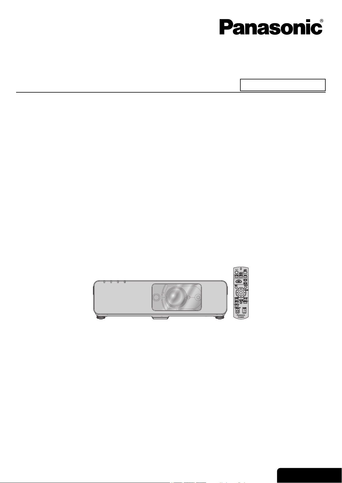
Operating Instructions
LCD Projector
Model No. PT-F100NTE
Commercial Use
PT-F100E
Before operating this product, please read the instructions carefully and save this manual for future use.
TQBJ0214-1
ENGLISH
Page 2
Information
Important Safety Notice
Important
Dear Panasonic Customer:
This instruction booklet provides all the necessary operating information that you might require. We hope it will help
you to get the most out of your new product, and that you will be pleased with your Panasonic LCD projector. The
serial number of your product may be found on its bottom. You should note it in the space provided below and retain
this booklet in case service is required.
WARNING: THIS APPARATUS MUST BE EARTHED.
WARNING: To prevent damage which may result in fire or shock hazard, do not expose this appliance
Machine Noise Information Ordinance 3. GSGV, January 18, 1991: The sound pressure level at the operator
position is equal or less than 70 dB (A) according to ISO 7779.
WARNING:
1. Remove the plug from the mains socket when this unit is not in use for a prolonged period of time.
2. To prevent electric shock, do not remove cover. No user serviceable parts inside. Refer servicing to qualified
service personnel.
3. Do not remove the earthing pin on the mains plug. This apparatus is equipped with a three prong earthingtype mains plug. This plug will only fit an earthing-type mains socket. This is a safety feature. If you are unable
to insert the plug into the mains socket, contact an electrician. Do not defeat the purpose of the earthing plug.
Model number: PT-F100NTE / PT-F100E
Serial number:
to rain or moisture.
CAUTION: To assure continued compliance, follow the attached installation instructions, which includes using
the provided power cord and shielded interface cables when connecting to computer or peripheral
device. If you use serial port to connect PC for external control of projector, you must use optional
RS-232C serial interface cable with ferrite core. Any unauthorized changes or modifications to this
equipment will void the user’s authority to operate.
Pursuant to at the directive 2004/108/EC, article 9(2)
Panasonic Testing Centre
Panasonic Service Europe, a division of Panasonic Marketing Europe GmbH
Winsbergring 15, 22525 Hamburg, F.R. Germany
ENGLISH - 2
Page 3
Important Safety Notice
Information on Disposal for Users of Waste Electrical & Electronic Equipment (private
households)
This symbol on the products and/or accompanying documents means that used electrical and
electronic products should not be mixed with general household waste.
For proper treatment, recovery and recycling, please take these products to designated collection
points, where they will be accepted on a free of charge basis. Alternatively, in some countries you may
be able to return your products to your local retailer upon the purchase of an equivalent new product.
Disposing of this product correctly will help to save valuable resources and prevent any potential
negative effects on human health and the environment which could otherwise arise from inappropriate
waste handling. Please contact your local authority for further details of your nearest designated collection point.
Penalties may be applicable for incorrect disposal of this waste, in accordance with national legislation.
For business users in the European Union
If you wish to discard electrical and electronic equipment, please contact your dealer or supplier for further
information.
Information on Disposal in other Countries outside the European Union
This symbol is only valid in the European Union.
If you wish to discard this product, please contact your local authorities or dealer and ask for the correct method of
disposal.
Important
Information
ENGLISH - 3
Page 4
Information
Important Safety Information
Important
Declaration of Conformity
Declaration of Conformity (DoC)
This equipment is in compliance with the essential requirements and other relevant provisions of Directive 1999/5/EC.
Customers can download a copy of the original DoC for this product from our DoC server: http://www.doc.panasonic.de
Contact in the EU: Panasonic Services Europe, a Division of Panasonic Marketing Europe GmbH, Panasonic Testing Centre,
Winsbergring 15, 22525 Hamburg, F.R.Germany
This product is intended to be used in the following countries.
Austria, Belgium, Bulgaria, Czech, Cyprus, Denmark, Estonia, Finland, France, Germany, Greece, Hungary, Iceland, Ireland, Italy, Latvia,
Lithuania, Luxembourg, Malta, Netherlands, Norway, Poland, Portugal, Romania, Slovenia, Slovak, Spain, Sweden, Switzerland & UK
Konformitätserklärung (KE)
Dieses Gerät entspricht den grundlegenden Anforderungen und den weiteren entsprechenden Vorgaben der Richtlinie 1999/5/EU.
Kunden können eine Kopie der Original-KE für dieses Produkt von unserem KE-Server herunterladen: http://www.doc.panasonic.de
Kontaktadresse in der EG: Panasonic Services Europe, a Division of Panasonic Marketing Europe GmbH, Panasonic Testing Centre,
Winsbergring 15, 22525 Hamburg, F.R.Germany
Dieses Produkt ist für den Einsatz in den folgenden Ländern vorgesehen.
Österreich, Belgien, Bulgarien, Tschechische Republik, Zypern, Dänemark, Estland, Finnland, Frankreich, Deutschland, Griechenland,
Ungarn, Island, Irland, Italien, Lettland, Litauen, Luxemburg, Malta, Niederlande, Norwegen, Polen, Portugal, Rumänien, Slowenien,
Slowakei, Spanien, Schweden, Schweiz und Großbritannien
Déclaration de Conformité (DC)
Cet appareil est conforme aux exigences essentielles et aux autres dispositions pertinentes de la Directive 1999/5/EC.
Les clients peuvent télécharger une copie de la DC originale pour ce produit à partir de notre serveur DC: http://www.doc.panasonic.de
Coordonnées dans l’UE : Panasonic Services Europe, a Division of Panasonic Marketing Europe GmbH, Panasonic Testing Centre,
Winsbergring 15, 22525 Hamburg, F.R.Germany
Ce produit est conçu pour l’utilisation dans les pays suivants.
Autriche, Belgique, Bulgarie, République Tchéquie, Chypre, Danemark, Estonie, Finlande, France, Allemagne, Grèce, Hongrie, Islande,
Irlande, Italie, Lettonie, Lituanie, Luxembourg, Malte, Pays-Bas, Norvège, Pologne, Portugal, Roumanie, Slovénie, Slovaquie, Espagne,
Suède, Suisse et Royaume-Uni
Declaración de conformidad (DC)
Este equipo cumple con los requisitos esenciales asi como con otras disposiciones de la Directiva 1999/5/CE.
El cliente puede descargar una copia de la DC original de este producto desde nuestro servidor DC: http://www.doc.panasonic.de
Contacto en la U.E.: Panasonic Services Europe, a Division of Panasonic Marketing Europe GmbH, Panasonic Testing Centre,
Winsbergring 15, 22525 Hamburg, F.R.Germany
Este producto ha sido desarrollado para el uso en los siguientes países.
Austria, Bélgica, Bulgaria, República Checa, Chipre, Dinamarca, Estonia, Finlandia, Francia, Alemania, Grecia, Hungría, Islandia, Irlanda,
Italia, Letonia, Lituania, Luxemburgo, Malta, Holanda, Noruega, Polonia, Portugal, Rumania, Eslovenia, Eslovaquia, España, Suecia,
Suiza y el Reino Unido
Dichiarazione di conformità (DoC)
Questo apparato é conforme ai requisiti essenziali ed agli altri principi sanciti dalla Direttiva 1999/5/CE.
I clienti possono scaricare la copia del DoC originale per questo prodotto dal nostro server DoC: http://www.doc.panasonic.de
Contatto nella EU: Panasonic Services Europe, a Division of Panasonic Marketing Europe GmbH, Panasonic Testing Centre,
Winsbergring 15, 22525 Hamburg, F.R.Germany
I prodotti sono stati prodotti per l’uso nei seguenti paesi.
Austria, Belgio, Bulgaria, Repubblica Ceca, Cipro, Danimarca, Estonia, Finlandia, Francia, Germania, Grecia, Irlanda, Islanda, Italia,
Lettonia, Lituania, Lussembugo, Malta, Olanda, Norvegia, Polonia, Portogallo, Romania, Regno Unito, Slovenia, Slovacchia, Spagna,
Svezia, Svizzera, Ungheria
ENGLISH - 4
Page 5
Important Safety Information
Important
Infomation
ENGLISH - 5
Page 6
Contents
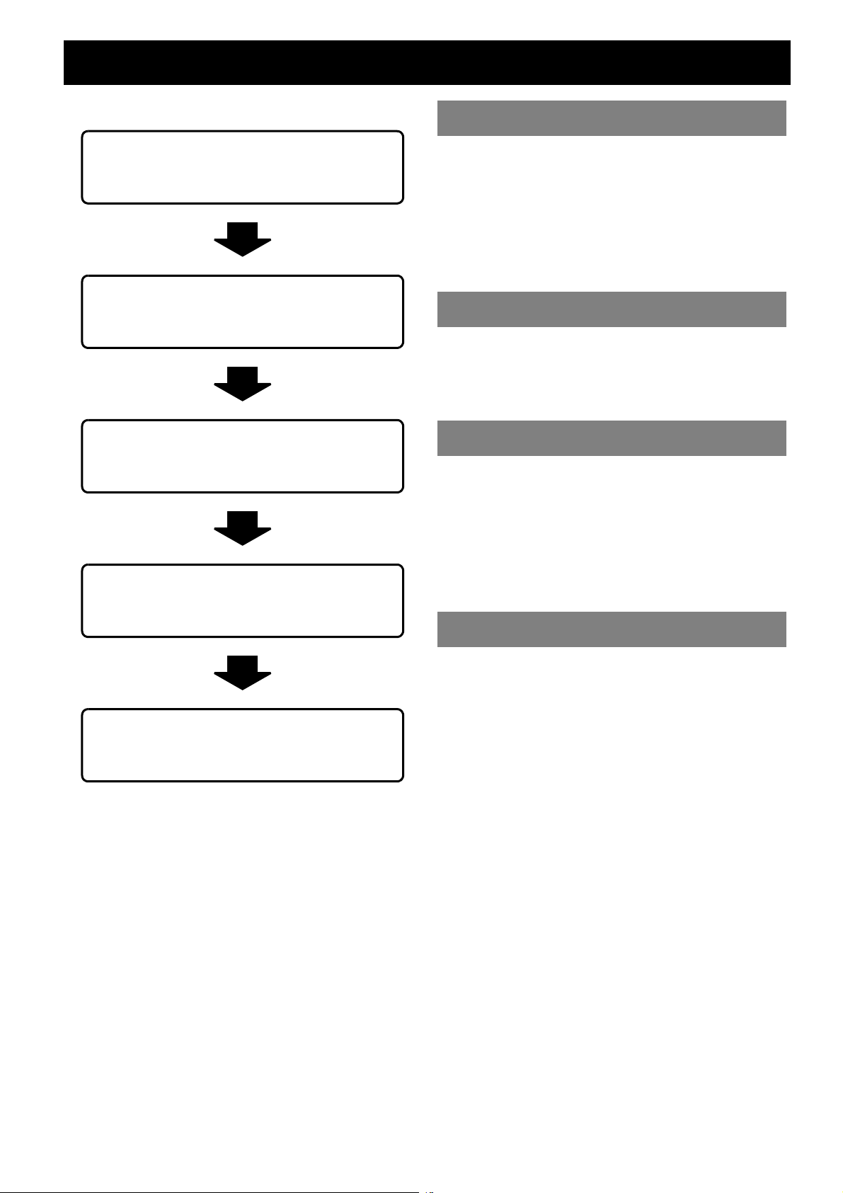
J Quick steps
Important Information
1. Set up your projector
See “Setting up” on page 16.
2. Connect with other devices
See “Connections” on page 20.
3. Prepare the Remote control
See “Remote control” on page 13.
4. Start projecting
See “Switching the projector on/off” on
page 22.
Important Safety Notice ............................................. 2
Declaration of Conformity..................................................4
Precautions with regard to safety............................. 8
WARNINGS ......................................................................8
CAUTIONS........................................................................9
Cautions when transporting ............................................10
Cautions when installing .................................................10
Cautions on use ..............................................................11
Accessories.....................................................................11
Preparation
Read this first ........................................................... 12
Minimum required setting screen ....................................12
About Your Projector ............................................... 13
Remote control................................................................13
Projector body .................................................................14
Getting Started
Setting up.................................................................. 16
Screen size and throw distance ......................................16
Projection method ...........................................................17
Front leg adjusters and throwing angle...........................17
Lens shift and positioning................................................ 18
Connections.............................................................. 20
Before connection to the projector ..................................20
Connecting with computers.............................................20
Connecting with AV equipment .......................................21
Basic Operation
5. Adjust the image
See “Menu Navigation” on page 29.
B When you start the projection for the first
time, the minimum required setting screen
for projection will be displayed.
See “Minimum required setting screen” on
page 12.
Switching the projector on/off ................................ 22
Mains lead.......................................................................22
POWER indicator............................................................22
Switching on the projector...............................................23
Switching off the projector...............................................23
Projecting an image ................................................. 24
Selecting the input signal ................................................24
Positioning the image......................................................24
Remote control operation........................................ 25
Operating range ..............................................................25
Setting up the image position automatically.................... 25
Switching the input signal................................................26
Using the laser pointer ....................................................26
Capturing an image.........................................................27
Stopping the projection temporary ..................................27
Resetting to the factory default settings..........................27
Projecting an image in INDEX-WINDOW mode..............27
Enlarging the centred area..............................................28
Controlling the volume of the speaker.............................28
ENGLISH - 6
Page 7

Contents
Settings
Menu Navigation .......................................................29
Navigating through the MENU ........................................29
Main menu and Sub-menu.............................................. 30
PICTURE menu..........................................................32
PICTURE MODE ............................................................ 32
CONTRAST .................................................................... 32
BRIGHTNESS.................................................................32
COLOUR......................................................................... 32
TINT ................................................................................32
SHARPNESS.................................................................. 32
COLOUR TEMPERATURE ............................................32
DAYLIGHT VIEW............................................................ 32
DETAILED SETUP ......................................................... 33
POSITION menu ........................................................34
KEYSTONE .................................................................... 34
POSITION....................................................................... 34
DOT CLOCK...................................................................34
CLOCK PHASE .............................................................. 34
ASPECT.......................................................................... 34
RESIZING.......................................................................35
FRAME LOCK.................................................................35
OPTION menu............................................................36
INPUT GUIDE.................................................................36
STARTUP LOGO............................................................36
COMPUTER2 SELECT .................................................. 36
FILTER SETUP...............................................................36
FILTER REMAINING ......................................................36
LAMP RUNTIME............................................................. 37
POWER OFF TIMER...................................................... 37
DIRECT POWER ON......................................................37
CONTROL PANEL..........................................................37
AUTO SETUP ................................................................. 37
SIGNAL SEARCH........................................................... 37
INSTALLATION .............................................................. 37
HIGHLAND .....................................................................38
TEST PATTERN............................................................. 38
DETAILED SETUP ......................................................... 38
SECURITY menu .......................................................39
INPUT PASSWORD ....................................................... 39
PASSWORD CHANGE................................................... 39
TEXT DISPLAY...............................................................39
TEXT CHANGE .............................................................. 39
NETWORK menu .......................................................40
Items in NETWORK menu..............................................40
Appendix
Technical Information .............................................. 46
List of compatible signals ............................................... 46
Serial terminal................................................................. 47
Computer connection guidance ...................................... 48
REMOTE terminal .......................................................... 49
Specifications ................................................................. 50
Screen size and throw distance for 16:9 aspect ratio..... 52
Dimensions..................................................................... 53
Trademark acknowledgements ...................................... 53
Index .......................................................................... 54
Important
Infomation
PreparationGetting StartedBasic OperationSettingsMaintenanceAppendix
Maintenance
TEMP, LAMP and FILTER Indicators .......................41
Managing the indicated problems ................................... 41
Care and Replacement .............................................42
Cleaning the projector..................................................... 42
Replacing the ARF (Auto Rolling Filter) .......................... 42
Replacing the Lamp unit ................................................. 43
Ceiling mount bracket safeguards .................................. 44
Troubleshooting........................................................45
ENGLISH - 7
Page 8

Information
Precautions with regard to safety
Important
WARNINGS
If you notice smoke, strange smells or noise coming
from the projector, disconnect the mains plug from
the mains socket.
Do not continue to use the projector in such cases,
otherwise fire or electric shocks could result.
Check that no more smoke is coming out, and then
contact an Authorised Service Centre for repairs.
Do not attempt to repair the projector yourself, as this
can be dangerous.
Do not install this projector in a place which is not
strong enough to take the full weight of the
projector.
If the installation location is not strong enough, it may
fall down or tip over, and severe injury or damage
could result.
Installation work (such as ceiling suspension)
should only be carried out by a qualified technician.
If installation is not carried out correctly, there is the
danger that injury or electric shocks may occur.
Do not use other than an authorised ceiling mount
bracket.
If foreign objects or water get inside the projector, or
if the projector is dropped or the cabinet is broken,
disconnect the mains plug from the mains socket.
Continued use of the projector in this condition may
result in fire or electric shocks.
Contact an Authorised Service Centre for repairs.
Do not overload the mains socket.
If the power supply is overloaded (for example, by
using too many adapters), overheating may occur
and fire may result.
Never attempt to modify or disassemble the
projector.
High voltages can cause fire or electric shocks.
For any inspection, adjustment and repair work,
please contact an Authorised Service Centre.
Clean the mains plug regularly to prevent it from
becoming covered in dust.
If dust builds up on the mains plug, the resulting
humidity can damage the insulation, which could
result in fire. Pull the mains plug out from the mains
socket and wipe it with a dry cloth.
If not using the projector for an extended period of
time, pull the mains plug out from the mains socket.
Do not handle the mains plug with wet hands.
Failure to observe this may result in electric shocks.
Insert the mains plug securely into the mains socket.
If the plug is not inserted correctly, electric shocks or
overheating could result.
Do not use plugs which are damaged or mains
sockets which are coming loose from the wall.
Do not place the projector on top of surfaces which
are unstable.
If the projector is placed on top of a surface which is
sloped or unstable, it may fall down or tip over, and
injury or damage could result.
Do not place the projector into water or let it become
wet.
Failure to observe this may result in fire or electric
shocks.
Do not do anything that might damage the mains
lead or the mains plug.
Do not damage the mains lead, make any
modifications to it, place it near any hot objects, bend
it excessively, twist it, pull it, place heavy objects on
top of it or wrap it into a bundle.
If the mains lead is used while damaged, electric
shocks, short-circuits or fire may result.
Ask an Authorised Service Centre to carry out any
repairs to the mains lead that might be necessary.
Do not place the projector on soft materials such as
carpets or sponge mats.
Doing so may cause the projector to overheat, which
can cause burns, fire or damage to the projector.
Do not place liquid containers on top of the
projector.
If water spills onto the projector or gets inside it, fire
or electric shocks could result.
If any water gets inside the projector, contact an
Authorised Service Centre.
Do not insert any foreign objects into the projector.
Do not insert any metal objects or flammable objects
into the projector or drop them onto the projector, as
doing so can result in fire or electric shocks.
Do not allow the + and - terminals of the batteries to
come into contact with metallic objects such as
necklaces or hairpins.
Failure to observe this may cause the batteries to
leak, overheat, explode or catch fire.
Store the batteries in a plastic bag and keep them
away from metallic objects.
Do not touch the leaked liquid from the batteries.
If you touch the leaked liquid, it may hurt your skin.
Immediately wash away the liquid with water and
seek medical advice.
If you get the leaked liquid in your eye, it may cause
blindness or damage. Never rub your eye, and
immediately wash away the liquid with water and
seek medical advice.
During a thunderstorm, do not touch the projector or
the cable.
Electric shocks can result.
ENGLISH - 8
Page 9

Precautions with regard to safety
Do not use the projector in a bath or shower.
Fire or electric shocks can result.
Do not place your skin into the light beam while the
projector is being used.
Strong light is emitted from the projector’s lens. If you
place directly into this light, it can hurt or damage
your skin.
Do not look into the lens while the projector is being
used.
Strong light is emitted from the projector’s lens. If you
look directly into this light, it can hurt and damage
your eyes.
Be especially careful not to let young children look
into the lens. In addition, turn off the power and
disconnect the mains plug when you are away from
the projector.
Do not place your hands or other objects close to the
air outlet port.
Heated air comes out of the air outlet port. Do not
place your hands or face, or objects which cannot
withstand heat close to this port [allow at least
50 cm (20") of space], otherwise burns or damage
could result.
Replacement of the lamp is recommended to be
carried out by a qualified technician.
The lamp has high internal pressure. If improperly
handled, explosion might result.
The lamp can easily become damaged if struck
against hard objects or dropped, and injury or
malfunctions may result.
When replacing the lamp, allow it to cool for at least
one hour before handling it.
The lamp cover gets very hot, and touching it can
cause burns.
Before replacing the lamp, be sure to disconnect the
mains plug from the mains socket.
Electric shocks or explosions can result if this is not
done.
Do not allow infants or pets to touch the remote
control unit.
Keep the remote control unit out of the reach of
infants and pets after using it.
Important
Information
CAUTIONS
Do not cover the air inlet port or the air outlet port.
Doing so may cause the projector to overheat, which
can cause fire or damage to the projector.
Do not place the projector in narrow, badly ventilated
places such as closets or bookshelves.
Do not place the projector on cloth or papers, as
these materials could be drawn into the air inlet port.
Do not set up the projector in humid or dusty places
or in places where the projector may come into
contact with oily smoke or steam.
Using the projector under such conditions may result
in fire, electric shocks or plastic deterioration. The
plastic deterioration may cause the falling down of
the projector which is mounted in the ceiling.
Do not set up the projector in a high temperature
environment, such as near a heater or in direct
sunlight.
Failure to observe this may result in fire, malfunction
or plastic deterioration.
Do not set up the projector outdoors.
The projector is designed for indoor use only.
Always disconnect all cables before moving the
projector.
Moving the projector with cables still attached can
damage the cables, which could cause fire or electric
shocks to occur.
Do not place any heavy objects on top of the
projector.
Failure to observe this may cause the projector to
become unbalanced and fall, which could result in
damage or injury.
Do not short-circuit, heat or disassemble the
batteries or place them into water or fire.
Failure to observe this may cause the batteries to
overheat, leak, explode or catch fire, and burns or
other injury may result.
When inserting the batteries, make sure the
polarities (+ and -) are correct.
If the batteries are inserted incorrectly, they may
explode or leak, and fire, injury or contamination of
the battery compartment and surrounding area may
result.
When disconnecting the mains lead, hold the plug,
not the lead.
If the mains lead itself is pulled, the lead will become
damaged, and fire, short-circuits or serious electric
shocks may result.
Use only the specified batteries.
If incorrect or different kind of batteries are used, they
may explode or leak, and fire, injury or contamination
of the battery compartment and surrounding area
may result.
ENGLISH - 9
Page 10

Information
Precautions with regard to safety
Important
Do not mix old and new batteries.
If the batteries are inserted incorrectly, they may
explode or leak, and fire, injury or contamination of
the battery compartment and surrounding area may
result.
Remove the used batteries from the remote control
promptly.
If you leave used batteries in the remote control for
an extended period of time, it may cause liquid
leaking, abnormal internal temperature rising or
explosion.
If not using the projector for an extended period of
time, disconnect the mains plug from the mains
socket and remove the batteries from the remote
control.
If dust builds up on the mains plug, the resulting
humidity may damage the insulation, which could
result in fire.
Keeping or leaving the remote control with batteries
inside may cause insulation deterioration, electrical
leakage or explosion which could result in fire.
Do not put your weight on this projector.
You could fall or the projector could break, and injury
may result.
Be especially careful not to let young children stand
or sit on the projector.
Disconnect the mains plug from the mains socket as
a safety precaution before carrying out any cleaning.
Electric shocks can result if this is not done.
If the lamp has broken, ventilate the room
immediately. Do not touch or bring your face close
to the broken pieces.
Failure to observe this may cause the user to absorb
the gas which was released when the lamp broke and
which contains nearly the same amount of mercury
as fluorescent lamps, and the broken pieces may
cause injury.
If you believe that you have absorbed the gas or that
the gas has got into your eyes or mouth, seek
medical advice immediately.
Ask your dealer about the replacement of the lamp
unit and check the inside of the projector.
Ask an Authorised Service Centre to clean inside the
projector at least once a year.
If dust is left to build up inside the projector without
being cleaned out, it can result in fire or problems
with operation.
It is a good idea to clean the inside of the projector
before the season for humid weather arrives. Ask
your nearest Authorised Service Centre to clean the
projector when required. Please discuss with the
Authorised Service Centre regarding cleaning costs.
We are constantly making efforts to preserve and maintain a clean environment. Please take non repairable
units back to your dealer or a recycling company.
Cautions when transporting
Do not subject the projector to excessive vibration
or shocks.
The projector lens need to be handled with care.
Cover the lens with the lens cover when transporting
the projector.
When transporting the projector, hold the body at
the bottom securely.
Do not hold the adjuster legs or the top cover to move
the projector, as this may damage the projector.
Cautions when installing
Avoid setting up in places which are subject to
vibration or shocks.
The internal parts can be damaged, which may cause
malfunctions or accidents.
Avoid setting up in places which are subject to
sudden temperature changes, such as near an air
conditioner or lighting equipment.
The life of the lamp may be shortened or the projector
may be turned off. See “TEMP indicator” on page 41.
Do not set up the projector near high-voltage power
lines or near motors.
The projector may be subject to electromagnetic
interference.
If installing the projector to the ceiling, ask a
qualified technician to carry out all installation work.
You will need to purchase the separate installation kit
(Model No. ET-PKF100H, ET-PKF100S).
Furthermore, all installation work is should only be
carried out by a qualified technician.
See “Ceiling mount bracket safeguards” on page 44
for the Safety cable installation.
If using this projector at high elevations
(above 1 400 m), set the HIGHLAND to ON. See
“HIGHLAND” on page 38.
Failure to observe this may result in malfunctions or
the life of the lamp or the other components may be
shortened.
ENGLISH - 10
Page 11
Cautions on use
Precautions with regard to safety
In order to get the best picture quality
Draw curtains or blinds over any windows and turn off
any lights near the screen to prevent outside light or
light from indoor lamps from shining onto the screen.
Do not touch the surfaces of the lens or the front
glass with your bare hands.
If the surface of the lens becomes dirty from
fingerprints or anything else, this will be magnified
and projected onto the screen. Moreover, when not
using the projector, close the Front panel cover.
Liquid crystal panel
Do not project the same image for long periods of
time, as this may remain as an afterimage on the
liquid crystal panel.
The liquid crystal panel of the projector is built with
very high precision technology to provide fine picture
details. Occasionally, a few stuck pixels may appear
on the screen as fixed points of blue, green or red. It
is recommended to switch off the projector once and
try after 1 hour later again. Please note that this does
not affect the performance of your LCD.
The projector has a high pressure mercury lamp and
that is characterised as follows.
The brightness of the lamp depends on the duration
of use.
The lamp may explode or shorten the lamp life by
shocks or chipping damage.
The lamp may explode only occasionally after using
the projector.
The lamp may explode if using the projector after the
instructed lamp replacement timing.
The lamp life is depends on individual lamp
characteristics, usage condition and the installation
environment. Especially the consecutive use of the
projector for more than 10 hours, or the frequent
switching on or off may greatly affect on the lamp life.
Screen
Do not apply any volatile substances which may
cause discolouration to the screen, and do not let it
become dirty or damaged.
Optical components
If you use the projector consecutively 6 hours every
day, the optical components may need to be replaced
in less than 1 year.
Important
Information
Accessories
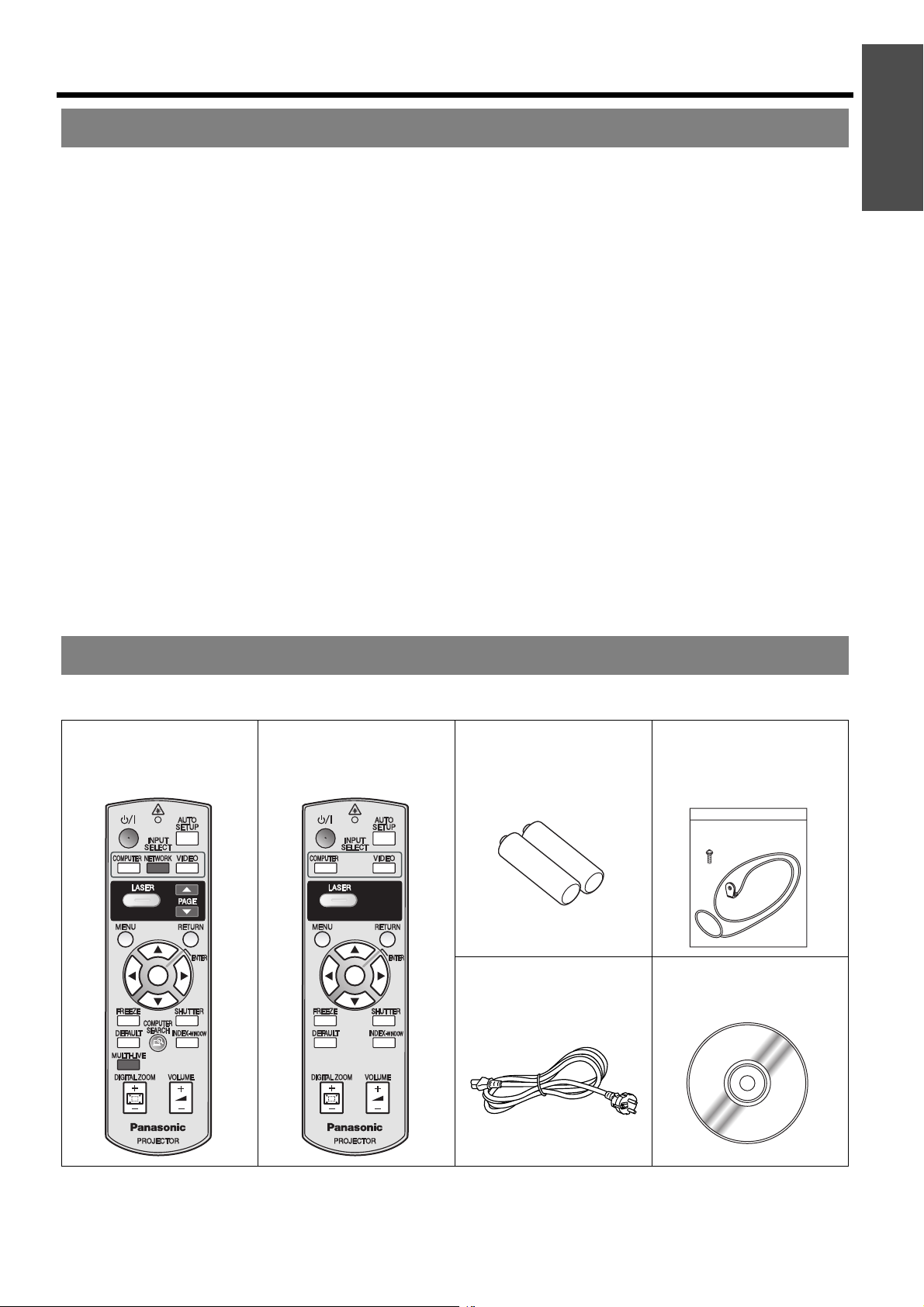
Make sure the following accessories are provided with your projector.
Remote control for
PT-F100NTE
N2QAYB000152
*1
(x1)
Remote control for
PT-F100E
N2QAYB000154
*2
(x1)
AA batteries for Remote
control (x2)
Mains lead (x1)
K2CM3DH00015
Safety cable
TTRA0141
Attachment screw (x1)
Safety cable (x1)
CD-ROM
TQBH9009
*3
(x1)
*1. PT-F100NTE only
*2. PT-F100E only
*3. PT-F100NTE only
ENGLISH - 11
Page 12
Read this first
Minimum required setting screen
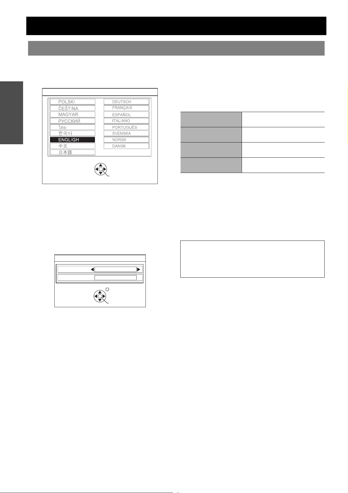
When you start the projection for the first time, the minimum required setting screen for projection will be displayed.
J LANGUAGE
Select the required language setting.
Preparation
LANGUAGE
Press F G I H buttons of the Remote control or
Control panel on the projector to highlight the
required language, and press ENTER to proceed to
the next setting.
J OPTION
Select the current projection method and fan speed
setting. If you need return to the previous setting,
press the RETURTN button.
SELECT
OPTION
INSTALLATION
HIGHLAND
SELECT
ENTER
FRONT/DESK
OFF
RETURN
ENTER
INSTALLATION
Press I H buttons of the Remote control or
Control panel on the projector to select the
required installation method. Press G to proceed to
the HIGHLAND setting.
FRONT/DESK
FRONT/CEILING
REAR/DESK
REAR/CEILING
Setting on a desk/floor and
projecting from front
Mounting in the ceiling and
projecting from front
Setting on a desk/floor and
projecting from rear
Mounting in the ceiling and
projecting from rear
HIGHLAND
If you use the projector at high elevation, the
HIGHLAND setting need to be ON to set the fan
speed high. Press I H to select the required
option. If you need to return to the INSTALLATION,
press F.
OFF The fan speed is low.
ON The fan speed is high.
NOTE:
• At 1 400 m (4 593 ft) above sea level, the setting must
be ON.
• The loudness of fan noise depends on the HIGHLAND
setting.
Press the ENTER button to start the projection.
Once you finish the minimum requirement setting, it will not be displayed again unless the projector is
initialised. See “INITIALISE ALL” on page 38.
You can change the settings from the MAIN MENU. See “Menu Navigation” on page 29.
ENGLISH - 12
Page 13
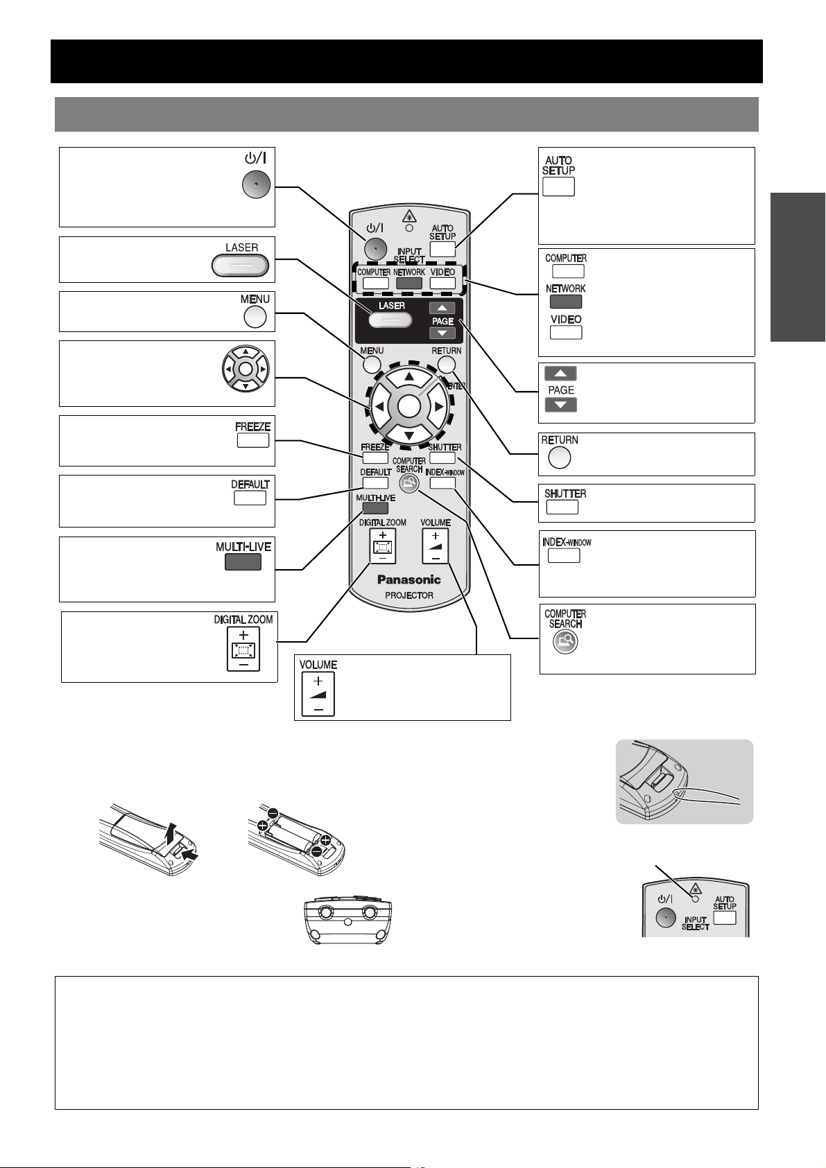
About Your Projector
Remote control
POWER button
While the MAIN POWER is on,
switch between stand-by mode
and projection mode.
(page 22)
Project a laser pointer.
(page 26)
Display the MAIN MENU.
(page 29)
Navigate through the
menus with FGIH, and
activate the menu item with
ENTER. (page 29)
Capture the projected image
as a frozen picture. (page 27)
Reset some of the settings to
the factory default settings.
(page 27)
MULTI-LIVE is only
for PT-F100NTE.
See CD-ROM
contents.
Control to change the
scale by means of digital
zoom. (page 28)
Control to adjust the
volume of the speakers.
(page 28)
Automatically adjust the
setting of DOT CLOCK,
CLOCK PHASE and SIGNAL
SEARCH for the projected
image of COMPUTER signal.
(page 25)
INPUT SELECT buttons
Switch the required input
signal button to select.
NETWORK button is
only for PT-F100NTE.
See CD-ROM contents.
PAGE buttons are only
for PT-F100NTE.
See CD-ROM contents.
Return to the previous menu.
(page 29)
Turn off the projection
temporarily.
Display the frozen image
while the display of
subsequent images
continues. (page 27)
COMPUTER SEARCH
button is only for
PT-F100NTE.
See CD-ROM contents.
Preparation
Battery compartment
1. Press the tab and lift up the cover.
2. Insert the batteries according to the polarity diagram
indicated inside.
Top view
Remote control signal and Laser pointer
beam emitters. (page 25)
Attaching a hand strap
You can attach a favourite strap
on to the Remote control.
Remote control indicator
If you press any button except the
LASER button, the Remote control
indicator will flash. If you press the
LASER button, it will lit.
Remote control
indicator
NOTE:
• Do not drop the Remote control.
• Avoid contact with liquids or moisture.
• Use manganese batteries or alkaline batteries with the Remote control.
• Do not attempt to modify or disassemble the Remote control. Contact an Authorised Service Centre for repairs.
• Do not keep pressing the Remote control buttons as this may shorten battery life.
• Do not point the laser in other people’s eyes or stare into beam.
• See “Remote control operation” on page 25.
ENGLISH - 13
Page 14
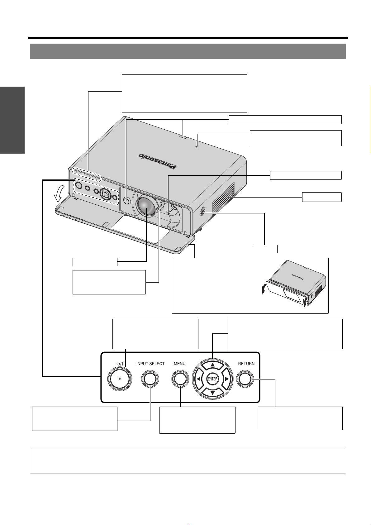
About Your Projector
Projector body
J Top and front view
Preparation
Indicators
POWER indicator (page 22)
LAMP indicator (page 41)
TEMP indicator (page 41)
FILTER indicator (page 41)
Remote control signal receptor (page 25)
ALS (Ambient Luminance Sensor)
(page 32)
Lens shift lever (page 18)
Air intake port
Projection lens
Levers
Focus lever (page 24)
Zoom lever (page 24)
Control panel
INPUT SELECT button
Switch to cycle through the input
method. (page 24)
Front panel cover
Hold both side of the top corner of
the Front panel cover to open or
close.
While not operating the
controls panel, keep the Front
panel cover closed.
POWER button
While the MAIN POWER is on,
switch between stand-by mode
and projection mode. (page 22)
MENU button
Display the MAIN MENU.
(page 29)
Speaker
Navigation buttons
Navigate through the menus with FGIH,
and activate the menu item with ENTER.
(page 29)
RETURN button
Return to the previous menu.
(page 29)
NOTE:
• Do not cover the ventilation openings or place anything within 50 cm (20") of them as this may cause damage or injury.
• While the projector is not in use, keep the FRONT PANEL COVER closed to protect the lens.
ENGLISH - 14
Page 15
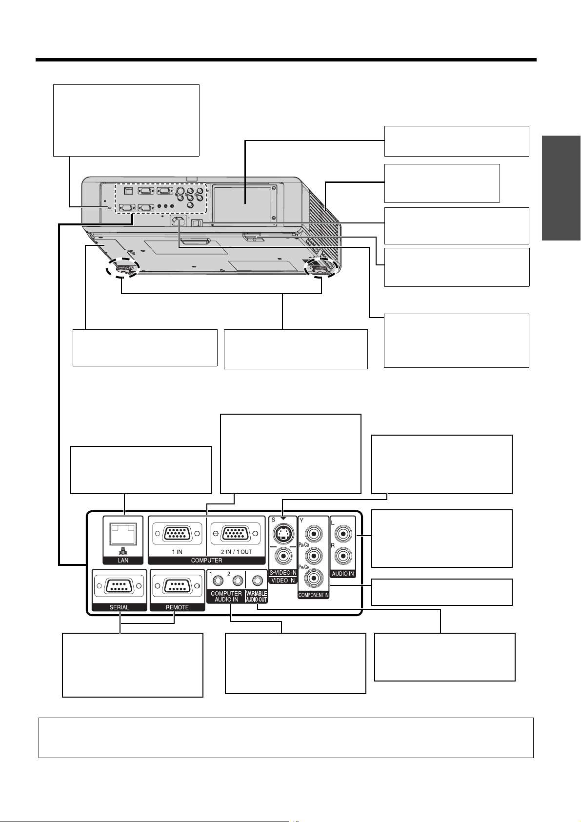
J Back and bottom view
Security lock
Attache the commercial shackle
lock, manufactured by Kensington,
to protect your projector.
Compatible with the Kensington
MicroSaver Security System.
About Your Projector
Lamp unit compartment
(page 43)
Air exhaust port
Heated air comes out of this
opening.
ARF (Auto Rolling Filter)
compartment
(page 42)
LAN
Connect a LAN cable for network
connection. This terminal is
PT-F100NTE only
Font leg adjusters
Screw up/down to adjust the
projection angle. (page 17)
COMPUTER1 IN
Connect an RGB signal cable from
a computer.
COMPUTER2 IN/1 OUT
Connect an RGB signal cable from
a computer.
Selectable for input
and output by menu operation.
MAIN POWER
Switch the projector on/off.
(page 23)
Burglar hook port
Attach a commercial burglar
prevention cable.
AC IN
Connect the Mains lead to supply
electronic power to the projector.
(page 22)
S-VIDEO IN
Connect a S-VIDEO signal cable.
VIDEO IN
Connect an RCA composite video
cable.
Preparation
AUDIO IN
Connect audio cables for inputting
audio signal corresponding to
VIDEO IN, S-VIDEO IN and
COMPONENT IN.
COMPONENT IN
Connect a YPBPR signal cable.
SERIAL
See “Serial terminal” on page 47.
REMOTE
See “REMOTE terminal” on
page 49.
COMPUTER AUDIO IN
Connect audio cables for inputting
audio signals corresponding to
COMPUTER1 IN and/or
COMPUTER2 IN/1 OUT.
VARIABLE AUDIO OUT
Connect an audio cables for
outputting audio signals to the
connected equipment.
NOTE:
• Do not cover the ventilation openings or place anything within 50 cm (20") of them as this may cause damage or injury.
• When a cable is connected to the VARIABLE AUDIO OUT, the built-in speaker will be disabled.
ENGLISH - 15
Page 16
Setting up
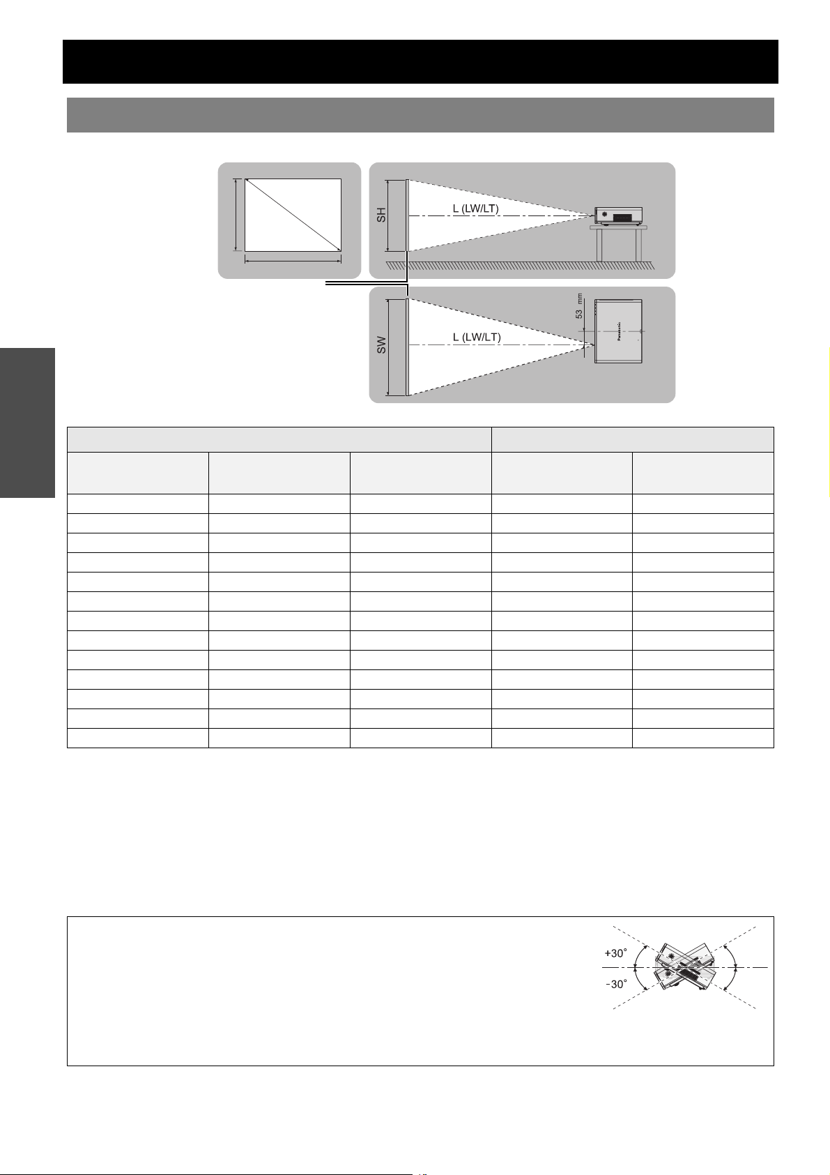
Screen size and throw distance
You can adjust the projection size with 2.0x zoom lens. Calculate and define the throw distance as follows.
S
Projected image
Getting Started
SH
Projection size (4 : 3) Throw distance (L)
D
SW
Screen
Screen diagonal
(SD)
33" (0.84 m) 0.50 m (1'7") 0.67 m (2'2") 1.9 m (6'2")
40" (1.02 m) 0.61 m (2') 0.81 m (2'7") 1.2 m (3'11") 2.4 m (7'10")
50" (1.27 m) 0.76 m (2'5") 1.02 m (3'4") 1.5 m (4'11") 3.0 m (9'10")
60" (1.52 m) 0.91 m (2'11") 1.22 m (4') 1.8 m (5'10") 3.6 m (11'9")
70" (1.78 m) 1.07 m (3'06") 1.42 m (4'7") 2.1 m (6'10") 4.2 m (13'9")
80" (2.03 m) 1.22 m (4') 1.63 m (5'4") 2.4 m (7'10") 4.8 m (15'8")
90" (2.29 m) 1.37 m (4'5") 1.83 m (6') 2.7 m (8'10") 5.4 m (17'8")
100" (2.54 m) 1.52 m (4'11") 2.03 m (6'7") 3.0 m (9'10") 6.0 m (19'8")
120" (3.05 m) 1.83 m (6') 2.44 m (8') 3.6 m (11'9") 7.2 m (23'7")
150" (3.81 m) 2.29 m (7'6") 3.05 m (10') 4.5 m (14'9") 9.0 m (29'6")
200" (5.08 m) 3.05 m (10') 4.06 m (13'3") 6.0 m (19'8") 12.1 m (39'8")
250" (6.35 m) 3.81 m (12'6") 5.08 m (16'8") 7.6 m (24'11") 15.1 m (49'6")
300" (7.62 m) 4.57 m (14'11") 6.10 m (20') 9.1 m (29'10") 18.1 m (59'4")
* All measurements above are approximate and may differ slightly from the actual measurements.
Screen height (SH) Screen width (SW)
Minimum distance
(LW)
Maximum distance
J Calculation methods for screen dimensions
You can calculate more detailed screen dimension from the screen diagonal.
SW (m) = SD (") x 0.0203 SH (m) = SD (") x 0.0152
LW (m) = 0.0304 x SD (") - 0.048 LT (m) = 0.0606 x SD (") - 0.057
(LT)
* The results above are approximate and may differ slightly from the actual measurements.
NOTE:
• See “Screen size and throw distance for 16:9 aspect ratio” on page 52.
• Do not use the projector at a raised or a horizontally tilted position as it may cause
malfunction of the projector.
• Make sure the projector lens surface is parallel with the screen. You can tilt the projector
body approximately ± 30° vertically. Overtilting may result in shortening the component’s
life.
• For the best quality of the projection image, install a screen where sun light or room light does not shine directly onto the
screen. Close window shades or curtains to block the lights.
ENGLISH - 16
Page 17
Setting up
Projection method
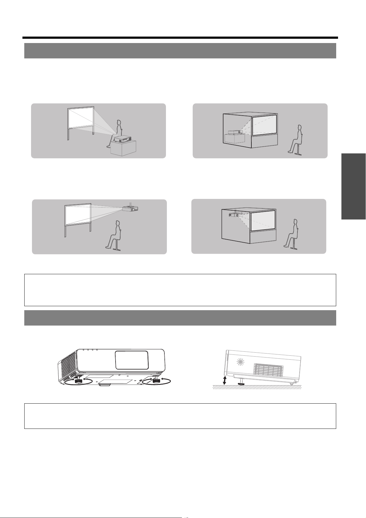
You can use the projector with any of the following 4 projection methods. To set the desired method in the projector,
See “INSTALLATION” on page 37.
J Setting on a desk/floor and
projecting from front
INSTALLATION: FRONT/DESK INSTALLATION: REAR/DESK
J Setting on a desk/floor and
projecting from rear
J Mounting in the ceiling and
projecting from front
INSTALLATION: FRONT/CEILING INSTALLATION: REAR/CEILING
NOTE:
• A translucent screen is required for rear projection.
• When mounting the projector in the ceiling, the optional ceiling mount bracket (ET-PKF100H, ET-PKF100S) is required.
• See “Ceiling mount bracket safeguards” on page 44.
J Mounting in the ceiling and
projecting from rear
Front leg adjusters and throwing angle
You can screw up/down the front leg adjusters to control the angle of the projector for adjusting the throwing angle.
See “Positioning the image” on page 24.
Getting Started
NOTE:
• Heated air comes out of the Air exhaust port. Do not touch the Air exhaust port directly.
• If keystone distortion occurs, see “KEYSTONE” on page 34.
ENGLISH - 17
Page 18
Setting up
Lens shift and positioning
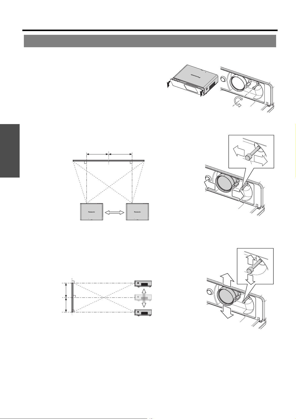
If the projector is not positioned right in front of the centre of the screen, you can adjust the projected image position
by moving the Lens shift lever within the shift range of the lens.
J Adjusting the Lens shift lever
1. Open the Front panel cover.
2. Screw the Lens shift lever counterclockwise to
unlock.
3. Move the Lens shift lever to adjust the projected
image position.
4. Screw the Lens shift lever clockwise to lock.
Q Horizontal shift
Getting Started
You can place the projector where the projector lens is up to 32% horizontally off-centre from the screen and
then adjust the image position with the Lens shift lever.
Up to about 32 %
of the projection
Shifting the lever right:
Moving to screen’s
right.
Up to about 32 %
of the projection
Shifting the lever left:
Moving to screen’s left.
Q Vertical shift
You can place the projector where the projector lens is up to 50% vertically off-centre from the screen and the
adjust the image position with the Lens shift lever.
Up to about 50 %
of the projection
Shifting the lever down:
Moving to screen’s
bottom.
Up to about 50 %
of the projection
ENGLISH - 18
Shifting the lever up:
Moving to screen’s top.
Page 19
Setting up
J Projector location range
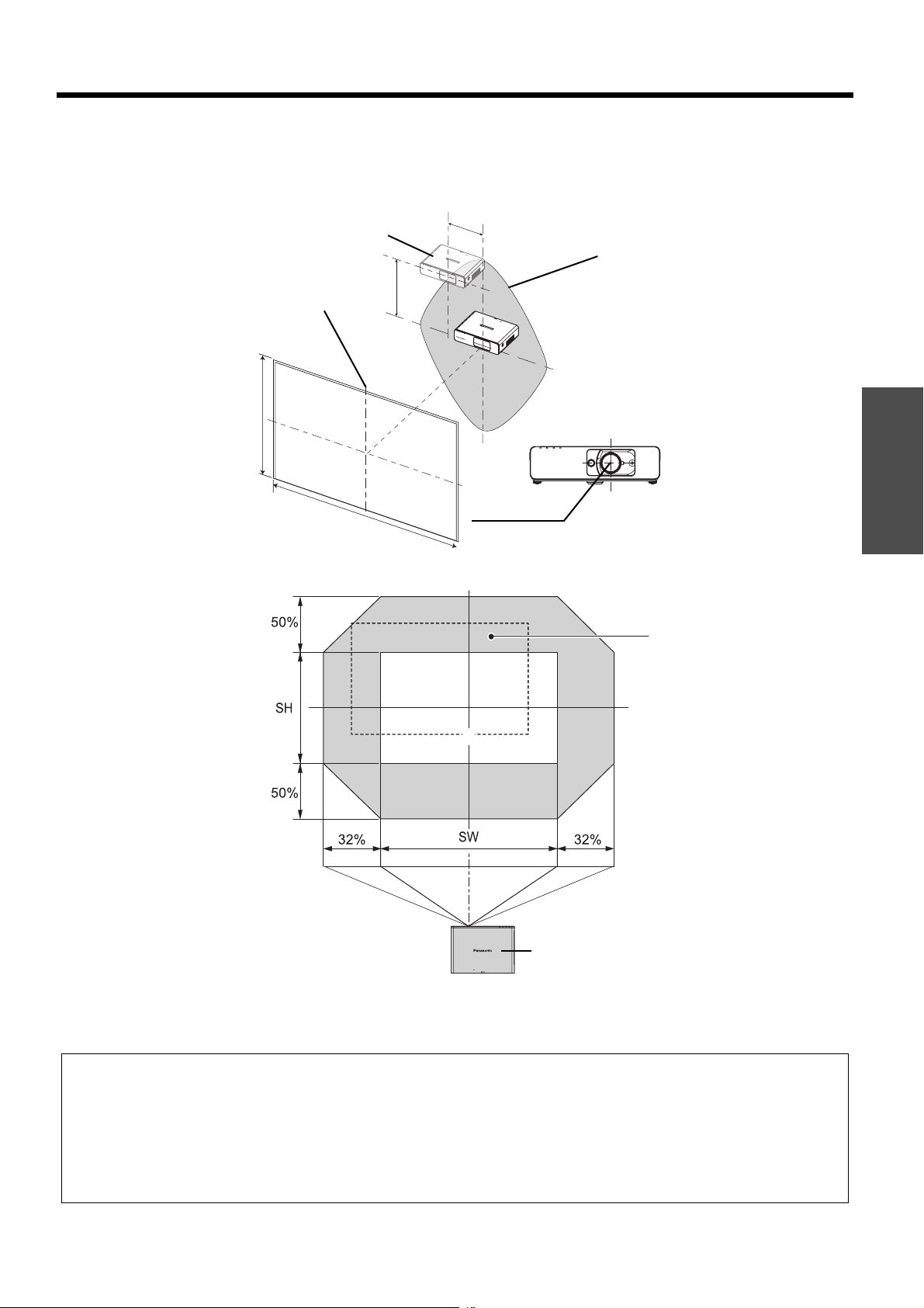
You can determine where to locate the screen and the projector by considering the lens shift possibilities. See
“Positioning the image” on page 24.
Q When the screen position is fixed
H
Projector
Placement
V
Vertical centre of
screen
SH
Screen
Centre of lens
SW
Getting Started
Q When the projector position is fixed
Shift range
Projector
NOTE:
• When the projector is located right in front of the screen and the Lens shift lever is centred, you will get the best quality of
the projection image.
• When the Lens shift lever is at the vertical limit of the shift range, you cannot move the lever to the horizontal limit,
likewise when the Lens shift lever is at the horizontal limit of the shift range, you cannot move the lever to the horizontal
limit.
• When the projector is tilted and you adjust KEYSTONE, the centre of the screen and the lens need to be realigned.
• Do not attempt to pull the Lens shift lever hard while adjusting.
ENGLISH - 19
Page 20
Connections
Before connection to the projector
Read and follow the operating and connecting instructions of each peripheral device.
The peripheral devices must be turned off.
Use cables that match each peripheral device to be connected.
If the input signal is affected by signal jitter, the projected image may have poor image quality and timebase
correction is effective.
Confirm the type of video signals. See “List of compatible signals” on page 46.
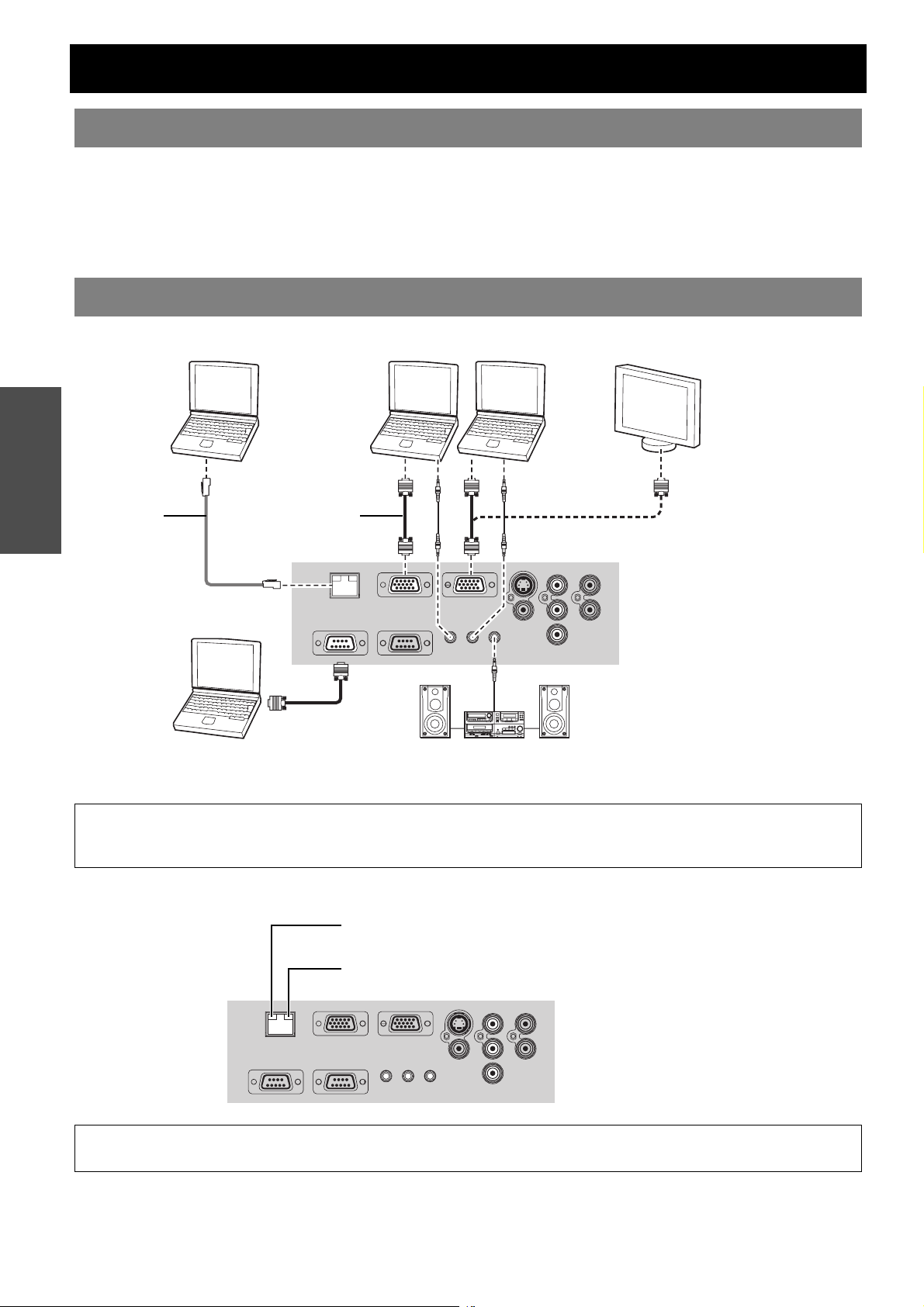
Connecting with computers
Getting Started
Computers Monitor
LAN cable
(Commercial)
Computer for
controlling
RGB signal cable
(Commercial)
Audio system
NOTE:
• When COMPUTER2 SELECT in the OPTION menu is set to OUTPUT, do not connect any input signals.
•See CD-ROM contents for the LAN network connection.
J LAN terminal
ACT lamp (Green)
Flashes when transmit data.
LINK lamp (Yellow)
Illuminates when a LAN cable is connected.
NOTE:
• Do not touch the metal parts of the LAN terminal. Failure to observe this may cause malfunction by static electricity.
ENGLISH - 20
Page 21
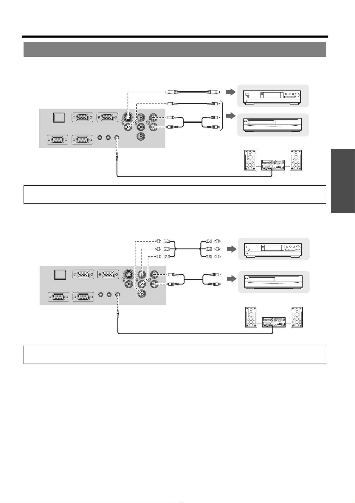
Connecting with AV equipment
J Connecting with VIDEO IN/S-VIDEO IN
Connections
To S-VIDEO output
To video output or
audio output
Audio system
NOTE:
• When you connect more than one AV equipment, switch the audio connection manually.
J Connecting with COMPONENT IN
DVD player
Video player
Getting Started
DVD player
To audio output
NOTE:
• If you connect the BNC cables, use with a commercial BNC-RCA adaptor.
Video player
Audio system
ENGLISH - 21
Page 22
Switching the projector on/off
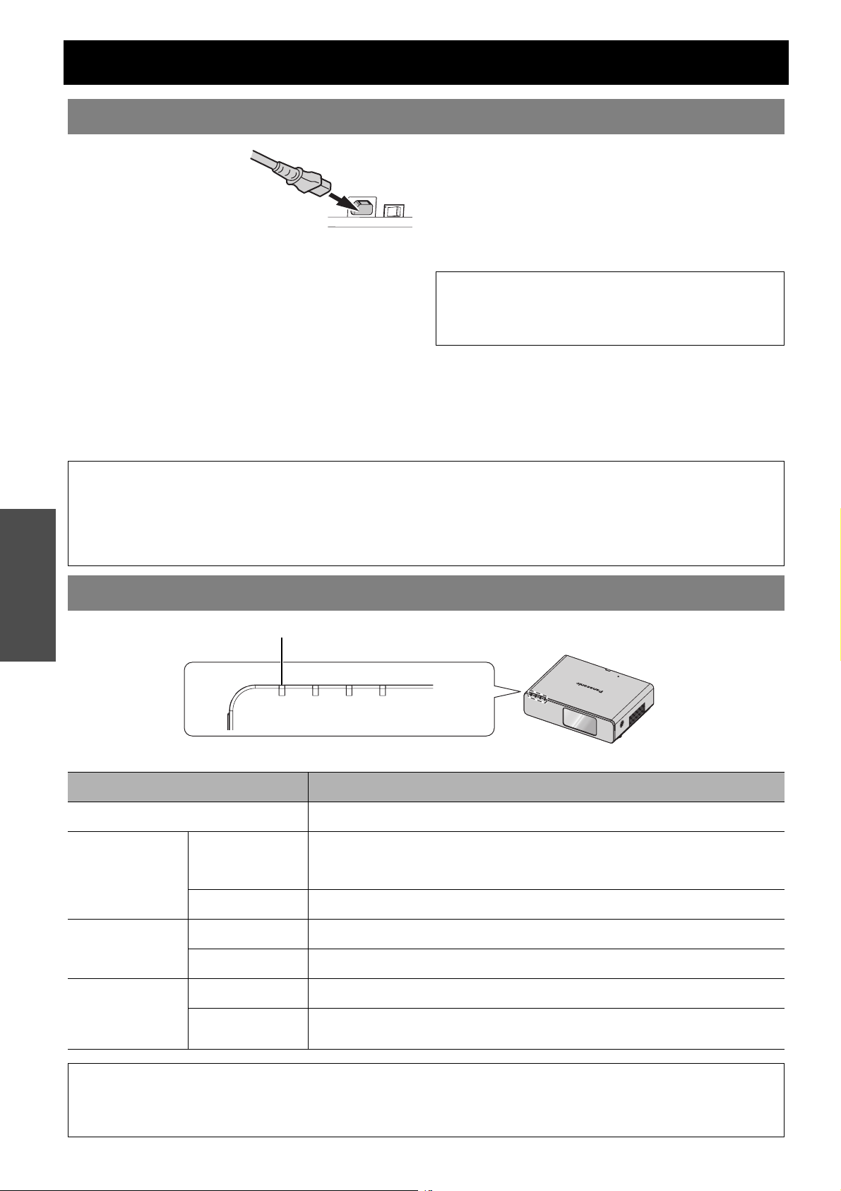
Mains lead
J Connecting
1. Make sure the shape
of the mains plug and
the AC IN connector
on the back of the
projector match, then
push the plug all the way in.
2. Connect the Mains lead to a mains socket.
J Disconnecting
1. Make sure the MAIN POWER is switched off and
unplug the Mains lead from the mains socket.
2. Hold the plug and unplug the Mains lead from the
AC IN connector on the back of the projector.
NOTE:
• Do not use other than a provided Mains lead.
Basic Operation
• Ensure all the input devices are connected and turned off before connecting the Mains lead.
• Do not force the connector as this may damage the projector and/or the mains lead.
• Dirt or dust build-up around plugs may cause fire or electrical hazards.
• Switch off the power to the projector when not in use.
J Direct power off function
You can disconnect the Mains lead from the
projector or switch off the MAIN POWER button
while projecting or soon after projecting. The
internal lamp cooling fan will keep operating by the
internal power supply.
NOTE:
• If the projector is switched on again while the internal
cooling fan is still operating by the internal power
supply, it may take a while to start the projection.
J Direct power on function
If you activate the DIRECT POWER ON, you can
start the projection only with connecting the Mains
lead or switching on the MAIN POWER. See
“DIRECT POWER ON” on page 37.
POWER indicator
POWER indicator
Indicator status Status
No illumination or flashing The MAIN POWER is switched off.
The MAIN POWER is switched on and the projector is in standby.
Lit
RED
Flashing Network connection is ready while the POWER is turned off.
Flashing The POWER is switched on and the projector is getting ready to project.
GREEN
Lit The projector is ready to project.
Lit The POWER is switched off and the projector is cooling the lamp.
ORANGE
Flashing
When the LAMP or TEMP indicator is flashing, the POWER indicator will
not be lit.
The POWER is switched on again when cooling the lamp and recovering
to projection mode. Recovery may take a while.
NOTE:
• If the projector is switched on again while the internal cooling fan is still operating by the internal power supply, it may take
a while to start the projection.
• The electric consumption in standby mode is 3 W.
ENGLISH - 22
Page 23
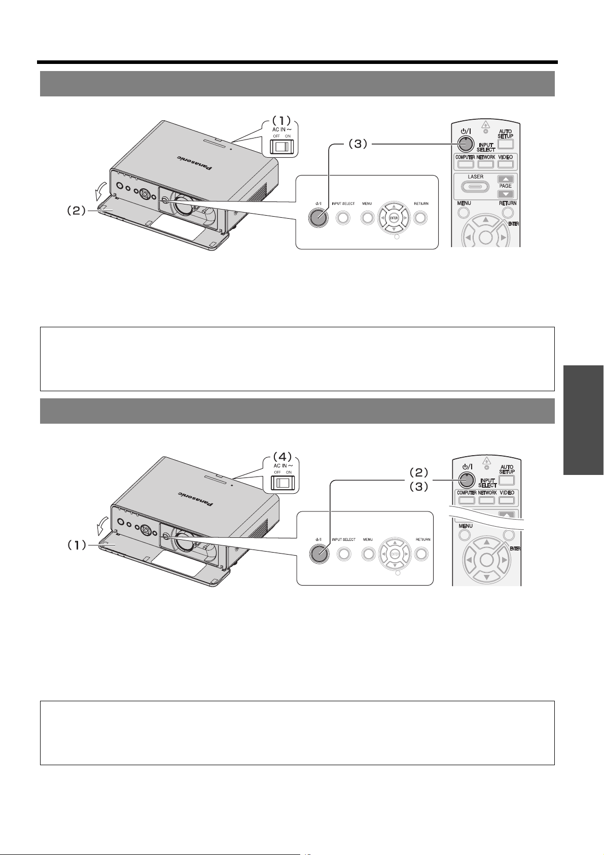
Switching on the projector
Switching the projector on/off
1. Switch the MAIN POWER on.
The power indicator lights up in RED.
2. Open the Front panel cover.
This is not necessary in Remote control operation.
3. Press the POWER button.
The power indicator lights up in GREEN after
flashing for a while.
The STARTUP LOGO is displayed on the screen.
See “STARTUP LOGO” on page 36.
NOTE:
• Some small rattling or tinkling sound may be heard when starting up, but this is normal and does not affect the
performance of the projector.
• If you disconnected the Mains lead or switched off the MAIN POWER while on projecting mode, the projection will start
with connecting the Mains lead or switching on the MAIN POWER. See “DIRECT POWER ON” on page 37.
Switching off the projector
Basic Operation
1. Open the Front panel cover.
This is not necessary in Remote control operation.
2. Press the POWER button.
The confirmation screen is displayed. It will
disappear and return to the projection after
10 seconds without any operation.
To return to the projection, press any button except
the POWER button.
3. Press the POWER button.
The power indicator lights up in ORANGE while
cooling the lamp, then illuminates RED when is
ready to switch off the MAIN POWER.
4. Switch off the MAIN POWER on the back of the
projector.
NOTE:
• Press the POWER twice or for a long duration to switch the power off.
• You can disconnect the Mains lead or switch off the MAIN POWER instead of following this procedure. See “DIRECT
POWER ON” on page 37.
• You can turn off the projector by pressing the POWER button longer than 0.5 seconds.
ENGLISH - 23
Page 24
Projecting an image
Selecting the input signal
1. Switch on the connected devices.
Press the play button of the required device.
2. Press the INPUT SELECT buttons to select the
required input method if needed. See “Switching
the input signal” on page 26.
The image will be projected on the screen.
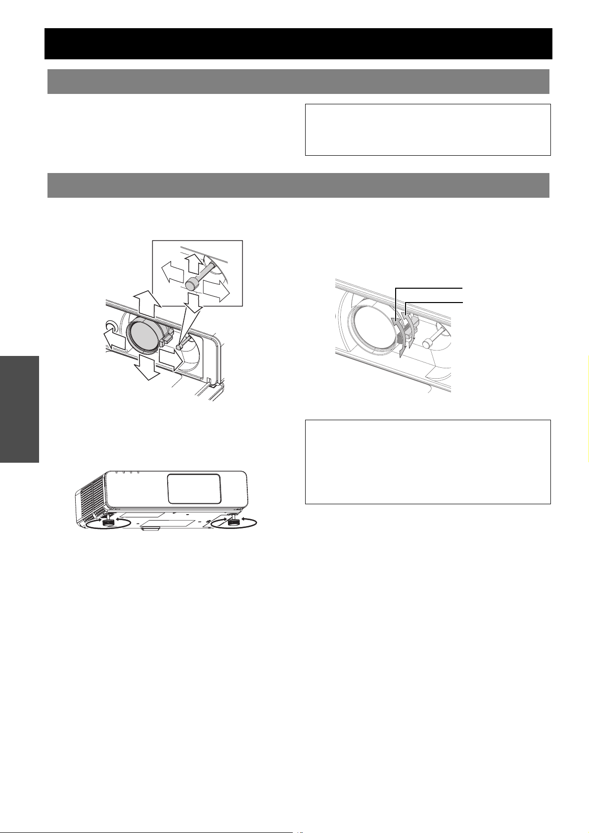
Positioning the image
NOTE:
• SIGNAL SEARCH is ON as default and the signal from
the connected devices is detected automatically. See
“SIGNAL SEARCH” on page 37.
Basic Operation
1. Open the Front panel cover.
2. Adjust the projected image with the Lens shift
lever. See “Lens shift and positioning” on page 18.
3. Adjust the angle of the projector.
Screw down the Front leg adjusters and adjust the
angle vertically.
See “Front leg adjusters and throwing angle” on
page 17.
4. Adjust the focus and the projected image size.
Turn the Focus lever and Zoom lever to adjust the
image.
You can confirm the adjusted effect with the TEST
PATTERN in OPTION menu. See “TEST PATTERN”
on page 38.
Focus lever
Zoom lever
NOTE:
• Do not touch the Air Exhaust port as this may cause
burns or injury.
• If keystone distortion occurs, see “KEYSTONE” on
page 34.
• If you adjust the focus, you may need to adjust the size
of the image by moving the Zoom lever again.
ENGLISH - 24
Page 25
Remote control operation
Operating range
You can operate the projector with the Remote control
within the remote range 15 m (49'2").
Q Facing to the projector
Ensure the Remote control emitter is facing to
the Remote control signal receptor on front/back
of the projector and press the required buttons to
operate.
Q Facing to the screen
Ensure the Remote control emitter is facing to
the screen and press the required buttons to
operate the projector. The signal will be reflected
off the screen. The operating range may differ due
to the screen material. This function may not be
effective with a translucent screen.
NOTE:
• Do not let strong light shine onto the signal receptor.
The Remote control may malfunction under strong
light such as fluorescent.
• If there are any obstacles between the Remote control
and the Remote control signal receptor, the Remote
control may not operate correctly.
Setting up the image position automatically
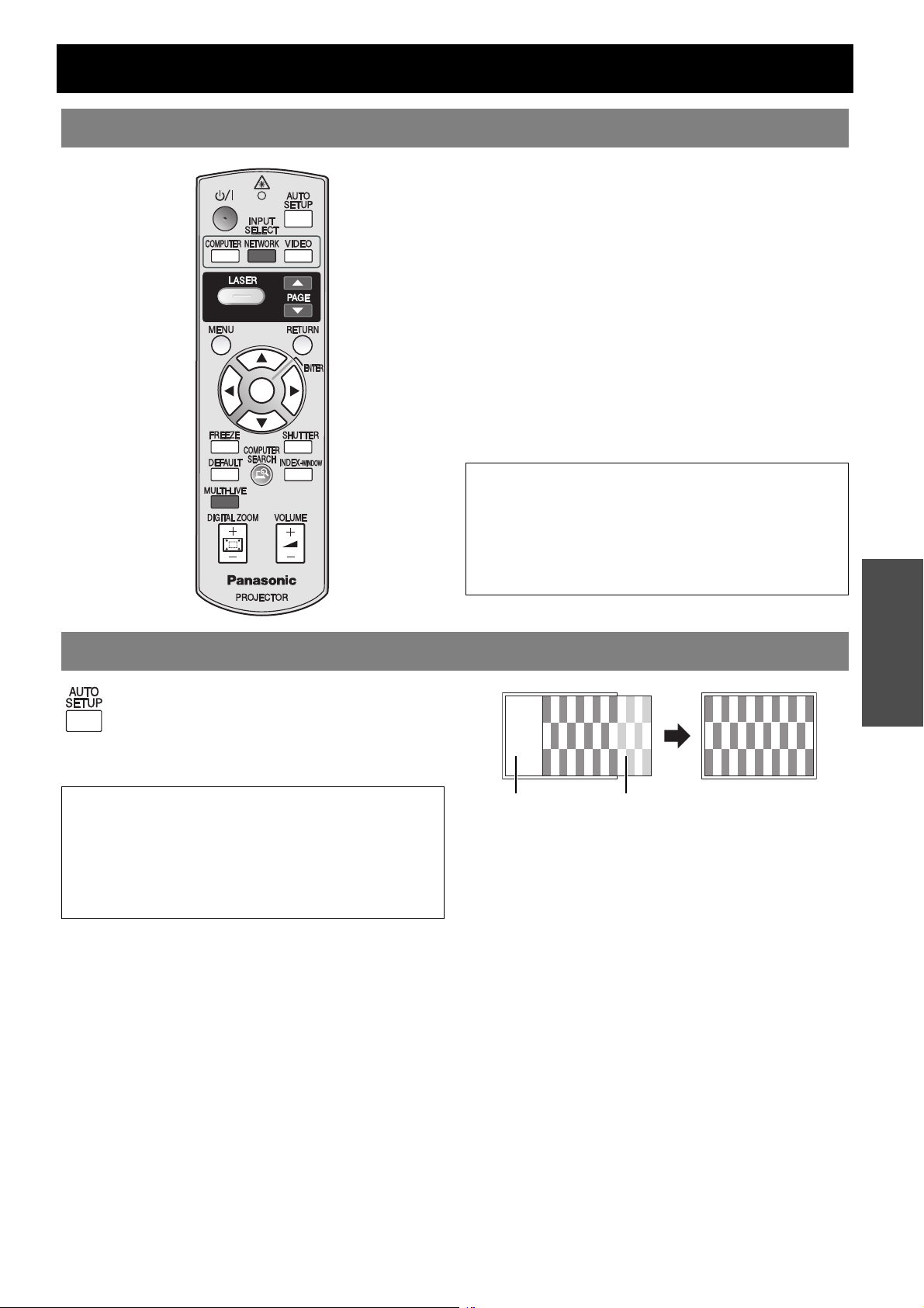
You can adjust the setting of POSITION, DOT
CLOCK and CLOCK PHASE in POSITION
menu automatically for the projected
COMPUTER signal image.
NOTE:
• If the dot clock frequency is 108 MHz or higher, AUTO
SETUP is not effective.
• If the projected image is dark or blurred around the
edge, AUTO SETUP may stop the processing before
complete. Project a much clearer or lighter image and
press the AUTO SETUP button again.
Screen Projected image
Basic Operation
ENGLISH - 25
Page 26
Remote control operation
Switching the input signal
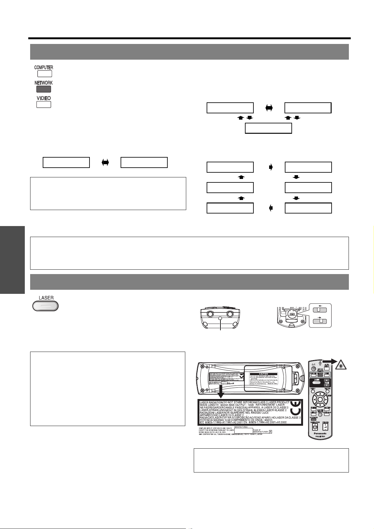
You can switch the input method manually by
pressing the COMPUTER, NETWORK
(PT-F100NTE only) and VIDEO buttons.
Press the required button several times or I
H to cycle through the input methods as
follows. The actual projected image will be
changed in a while.
The graphical guidance will be displayed on the upper
right of the projected image and you can confirm the
selected input method which is highlighted in yellow. See
“INPUT GUIDE” on page 36.
J Pressing the COMPUTER button
COMPUTER1
NOTE:
• Only when the COMPUTER2 SELECT is set to INPUT,
you can switch between COMPUTER1 and
COMPUTER2.
Basic Operation
NOTE:
• If you select an unplugged input method, the guidance will blink on and off several times.
• See “List of compatible signals” on page 46.
• See “Connections” on page 20.
COMPUTER2
J Pressing the NETWORK button
The NETWORK button is only for PT-F100NTE.
See CD-ROM contents for more detailed information.
J Pressing the VIDEO button
VIDEO
COMPONENT
S-VIDEO
J Pressing the INPUT SELECT
button on the projector
COMPUTER1
NETWORK
COMPONENT
NETWORK is only for PT-F100NTE.
COMPUTER2
S-VIDEO
VIDEO
Using the laser pointer
You can highlight items on the screen with
the red laser pointer while projecting the
image in presentations or visual
demonstrations as an eye-catching pointing
device.
Hold down the LASER button to goes on the
laser pointer and release to goes off.
NOTE:
• The laser pointer should never be projected directly into
the eyes of a person or animal.
• Do not aim the laser at reflective surfaces.
• Do not allow children to use laser pointer.
• Never look directly into the laser beam.
• The laser pointer is not effective with translucent
screens.
• Please read the cautions on the Remote control.
• This is a Class 2 laser product.
J Deactivating the LASER button
You can deactivate the LASER button for an
accidental operation.
1. Open the battery compartment cover of the
Remote control.
2. Slide the switch tab.
3. Close the battery compartment cover of the
Remote control.
See “Battery compartment” on page 13.
Deactivating switch Top view
On
Off
Laser pointer beam emitter
Cautions
CAUTION: Use of controls of adjustments or performance
of procedures other than those specified herein may result in
hazardous radiation exposure.
ENGLISH - 26
Page 27
Capturing an image
Remote control operation
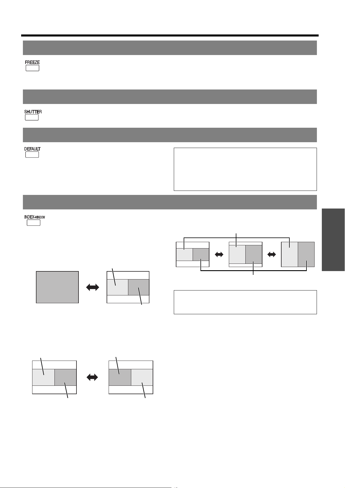
When projecting an image, press FREEZE to
capture the projected image and display it on
the screen as a still picture. While the image is
frozen, the sound will be stopped.
Press the FREEZE button to return to the projection.
Stopping the projection temporary
You can turn off the lamp and stop the
projection temporary for electrical power save.
Press the SHUTTER button to return to the projection.
Resetting to the factory default settings
You can reset most of the customised settings
to the factory defaults by pressing the
DEFAULT button of the Remote control.
Display the required sub menu or the menu
items and press the DEFAULT button again.
See “Main menu and Sub-menu” on page 30.
NOTE:
• Some menu items are not available to reset by pressing
the DEFAULT button. Adjust each menu items
manually.
• To reset all the settings to the factory defaults, see
“INITIALISE ALL” on page 38.
Projecting an image in INDEX-WINDOW mode
You can project an image in split 2 windows
as an INDEX-WINDOW, one is frozen, stored
in memory and displayed on the screen’s left
side, while the display of subsequent images
continues on the right.
To escape from the INDEX-WINDOW, press
the MENU or RETURN button.
Q Changing the image size
Press F G to switch and cycle through in 3 size.
Frozen image
Projected image
Frozen image
Continuing image
Q Switching the position
In default, the frozen image is displayed on the left
and the subsequent image is displayed on the
right. Press IH to switch the position.
Frozen image
Continuing image
Continuing image
Frozen image
Basic Operation
Continuing image
NOTE:
• If you change the window size, the aspect ratio of the
image is changed and becomes vertically elongated.
Q Capturing a new image
While in INDEX-WINDOW mode, press ENTER to
capture a new image and the frozen image window
will be updated in a while.
ENGLISH - 27
Page 28

Remote control operation
Enlarging the centred area
You can enlarge the projected image down
to a centred area for emphasizing within the
range of 1x to 2x.
Q Enlarging the image
1. Press DIGITAL ZOOM +/- once.
The centred area of the image will then be enlarged
to 1.5x.
2. Adjust the image size by pressing DIGITAL ZOOM
+/-.
The image size will be changed in steps of 0.1.
Basic Operation
NOTE:
• When the COMPUTER signal is projected, the enlargement range will be changed to 1x to 3x. When the FRAME LOCK
in POSITION menu is set to ON, the enlargement range is 1x to 2x. See “FRAME LOCK” on page 35.
• When the input signal is changed while the DIGITAL ZOOM is activated, the DIGITAL ZOOM will be cancelled.
• While the DIGITAL ZOOM is activated, FREEZE is not available.
Q Shifting the centre point
Press F G I H to shift the centre point.
Controlling the volume of the speaker
You can control the volume of the built-in
speakers and output sound. Press +/- to
control the volume.
NOTE:
• Power consumption can be reduced if the volume level
is lowered.
ENGLISH - 28
Page 29
Menu Navigation
KEYSTONE
KEYSTONE
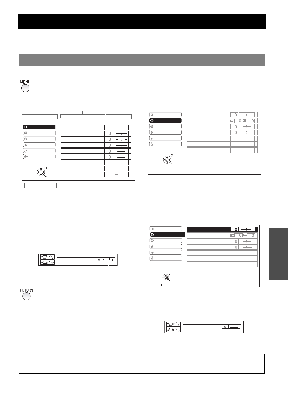
The menu system allows you to access functions which do not have their own dedicated buttons on the Remote
control. The menu options are structured and categorised. You can navigate through the menu with F G H I
buttons.
Navigating through the MENU
J Displaying the Main menu
Press the MENU button to display the Main
menu and the operating guidance.
Current
Main menu Sub-menu
PICTURE
POSITION
LANGUAGE
OPTION
SECURITY
NETWORK
RETURN
SELECT
PICTURE MODE
CONTRAST
BRIGHTNESS
COLOUR
TINT
SHARPNESS
COLOUR TEMPERATURE
DAYLIGHT VIEW
DETAILED SETUP
ENTER
settings
STANDARD
STANDARD
AUTO
Operating guidance
Contains the required buttons to adjust the settings.
J Adjusting with the bar scale
items
J Operating procedure
1. Press F G to scroll to the required Main menu
item and press ENTER to select.
The selected item is highlighted in orange and the
Sub-menu is displayed on the right.
See “Main menu and Sub-menu” on page 30.
PICTURE
POSITION
LANGUAGE
OPTION
SECURITY
NETWORK
RETURN
SELECT
2. Press F G to scroll to the required Sub-menu
item and press I H or ENTER to adjust.
The selected item is called up and the other menu
items disappear from the screen. Called up item will
be disappear after 5 seconds and return to the menu
mode.
If there is a lower level, the next level will be
displayed.
ENTER
KEYSTONE
POSITION
DOT CLOCK
CLOCK PHASE
ASPECT
RESIZING
FRAME LOCK
4:3
ON
OFF
The triangle mark under the bar indicates factory
default setting and the square indicates the current
setting.
Current setting
KEYSTONE
Default
J Returning to the previous menu
Press the MENU or RETURN button to return to
the previous menu. Press repeatedly to escape
from the menu mode and return to the
projection.
PICTURE
POSITION
LANGUAGE
OPTION
SECURITY
NETWORK
SELECT
DEFAULT
RETURN
ENTER
3. Press I H to adjust or set the selected item.
For items using a bar scale, the current settings are
displayed on the left of the bar scale.
You can cycle through the options of an item by
pressing I H.
4. Press MENU or RETURN to return to the previous
menu.
NOTE:
• See “Resetting to the factory default settings” on page 27 to reset each menu items.
• See “INITIALISE ALL” on page 38 to reset all the settings.
KEYSTONE
POSITION
DOT CLOCK
CLOCK PHASE
ASPECT
RESIZING
FRAME LOCK
KEYSTONE
4:3
ON
OFF
Settings
ENGLISH - 29
Page 30
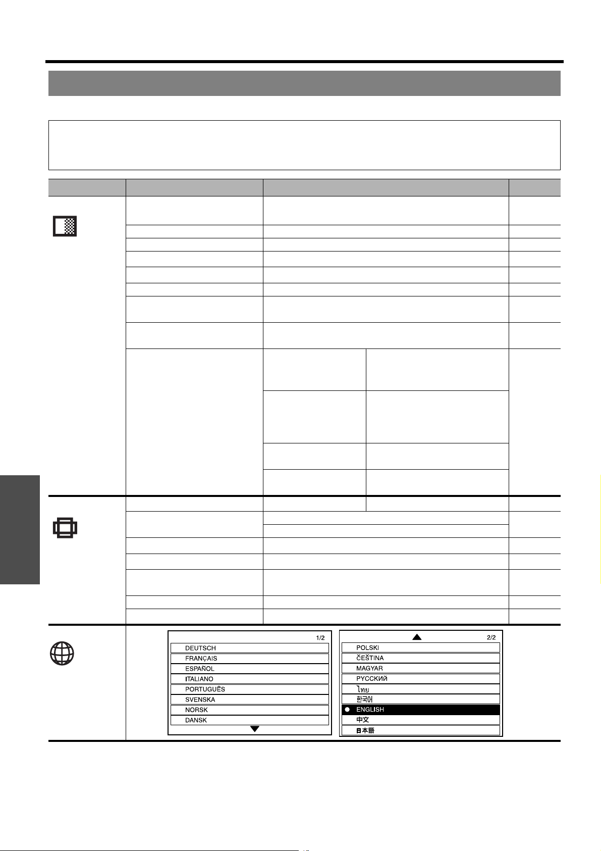
Menu Navigation
Main menu and Sub-menu
The Main menu has 6 options. Select the required menu item and press ENTER to display the Sub-menu.
NOTE:
• Some default settings vary by the selected input signal.
• Sub-menu items vary according to the selected input signal.
• Some settings are adjustable without any signals.
Main menu Sub-menu Options ( * is default setting) Page
PICTURE PICTURE MODE NATURAL
Settings
POSITION
LANGUAGE
DYNAMIC
STANDARD* BLACKBOARD
CONTRAST • Default: 0 page 32
BRIGHTNESS • Default: 0 page 32
COLOUR
*2
TINT
*2
• Default: 0 page 32
• Default: 0 page 32
SHARPNESS • Default: 0 page 32
COLOUR TEMPERATURE LOW STANDARD* page 32
HIGH
DAYLIGHT VIEW AUTO* ON page 32
OFF
DETAILED SETUP
*3
WHITE BALANCE
*4
WHITE BALANCE RED page 33
WHITE BALANCE GREEN
• Default: 0 WHITE BALANCE BLUE
TV-SYSTEM AUTO* NTSC
(S-VIDEO/VIDEO
signals only)
NTSC 4.43 PAL
PAL-M PAL-N
SECAM
STILL MODE OFF*
(S-VIDEO/VIDEO) ON
NOISE REDUCTION ON*
(S-VIDEO/VIDEO) OFF
KEYSTONE
*5
• Default: 0 page 34
POSITION H • Default: 0 page 34
V • Default: 0
DOT CLOCK
*4
CLOCK PHASE
*6
• Default: 0 page 34
• Default: 0 page 34
ASPECT 4:3* S4:3 page 34
16:9 AUTO
RESIZING OFF* ON page 35
FRAME LOCK
*2
OFF* ON page 35
*1
page 32
*1. Default setting for COMPUTER/COMPONENT signals
*2. Not available with COMPUTER/NETWORK signals
*3. VIDEO/S-VIDEO/COMPUTER signals only
*4. COMPUTER signals only
*5. Only KEYSTONE is available with NETWORK signals
*6. COMPUTER/COMPONENT signals only
ENGLISH - 30
Page 31
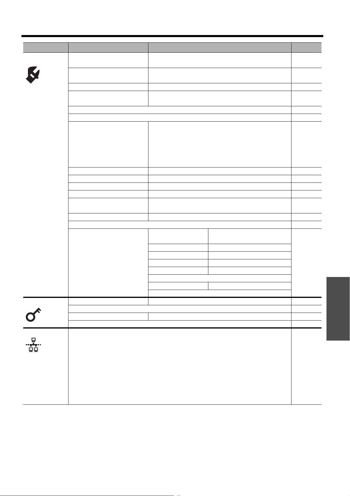
Menu Navigation
Main menu Sub-menu Options ( * is default setting) Page
OPTION INPUT GUIDE DETAILED* SIMPLE page 36
OFF
STARTUP LOGO ON* OFF page 36
USER
COMPUTER2 SELECT INPUT* OUTPUT page 36
FILTER SETUP 1 3 page 36
2
FILTER REMAINING page 36
LAMP RUNTIME page 37
POWER OFF TIMER OFF*page37
15 MIN. 40 MIN.
20 MIN. 45 MIN.
25 MIN. 50 MIN.
30 MIN. 55 MIN.
35 MIN. 60 MIN.
DIRECT POWER ON OFF* ON page 37
CONTROL PANEL VALID* INVALID page 37
AUTO SETUP AUTO* BUTTON page 37
SIGNAL SEARCH ON* OFF page 37
INSTALLATION FRONT/DESK* REAR/DESK page 37
FRONT/CEILING REAR/CEILING
HIGHLAND OFF* ON page 38
TEST PATTERN page 38
DETAILED SETUP OSD DESIGN TYPE1 TYPE2 page 38
TYPE3
SXGA MODE SXGA SXGA+
XGA MODE XGA WXGA
BLACKBOARD ON* OFF
BACK COLOUR BLUE* BLACK
VOLUME
AUDIO BALANCE • Default: 0
INITIALISE ALL
SECURITY INPUT PASSWORD OFF* ON page 39
PASSWORD CHANGE page 39
TEXT DISPLAY OFF* ON page 39
TEXT CHANGE page 39
NETWORK WIRED LAN page 40
WIRELESS LAN
NAME CHANGE
INPUT PASSWORD
PASSWORD CHANGE
(PT-F100NTE
only. See CD-
ROM contents)
NETWORK STANDBY
WEB CONTROL
LIVE MODE CUT IN
STATUS
INITIALISE
Settings
ENGLISH - 31
Page 32
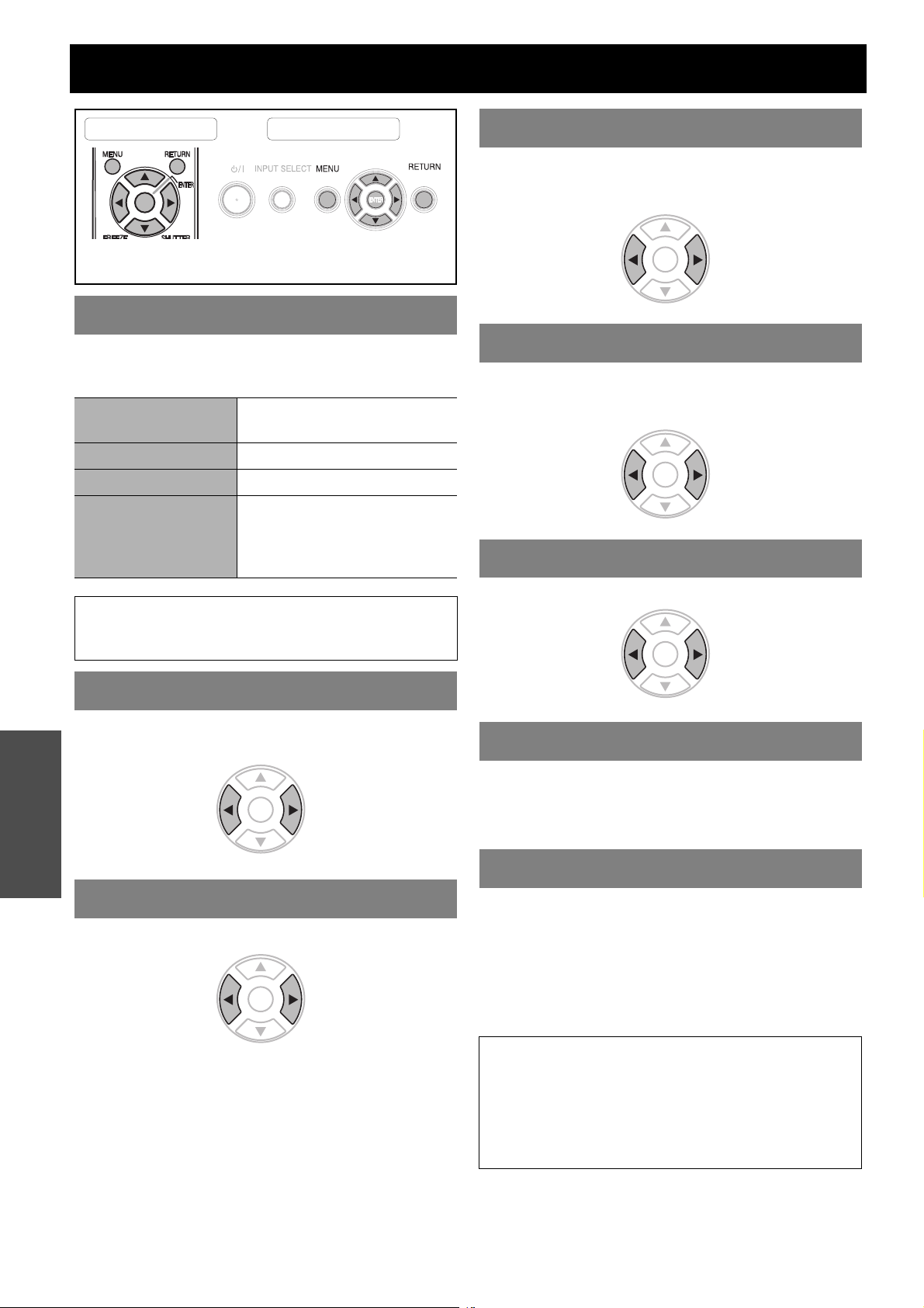
PICTURE menu
Remote control Control panel
See “Navigating through the MENU” on page 29.
See “Main menu and Sub-menu” on page 30.
PICTURE MODE
Depending on the projection environment, you can use
these preset parameter settings to optimise image
projection. Press I H to cycle through the options.
NATURAL
STANDARD Setting for a general image
DYNAMIC Bright and sharp setting
BLACKBOARD
Reproduces the original colour
of the image
Setting for when projecting on
a blackboard
See “BLACKBOARD” on
page 38.
COLOUR
You can adjust the colour saturation of the projected
image. (Available with signals from VIDEO/S-VIDEO/
COMPONENT only)
DarkerLighter
TINT
You can adjust the skin tone in the projected image.
(Available with signals from VIDEO/S-VIDEO/
COMPONENT only)
More
reddish
More
greenish
SHARPNESS
NOTE:
• It may take for a while until the selected mode is
stabilised.
CONTRAST
You can adjust the contrast of the projected image.
Adjust the BRIGHTNESS in advance if necessary.
Settings
HigherLower
BRIGHTNESS
You can adjust the brightness of the projected image.
BrighterDarker
You can adjust the sharpness of the projected image.
Less
sharp
More
sharp
COLOUR TEMPERATURE
You can adjust the white balance of the projected image.
LOW More bluish
STANDARD Balanced white
HIGH More reddish
DAYLIGHT VIEW
You can keep the projected image bright and vivid even
in well-lit rooms where the ambient light sources cannot
be controlled, such as when a door opens or when
window coverings fail to block out sunlight.
AUTO: Automatic adjustment
ON: Active
OFF: Deactive
ENGLISH - 32
NOTE:
• Do not cover the ALS (Ambient Luminance Sensor) of
the projector. See “ALS (Ambient Luminance Sensor)”
on page 14.
• AUTO is not available when INSTALLATION setting in
OPTION menu is set to REAR/DESK or REAR/
CEILING.
Page 33
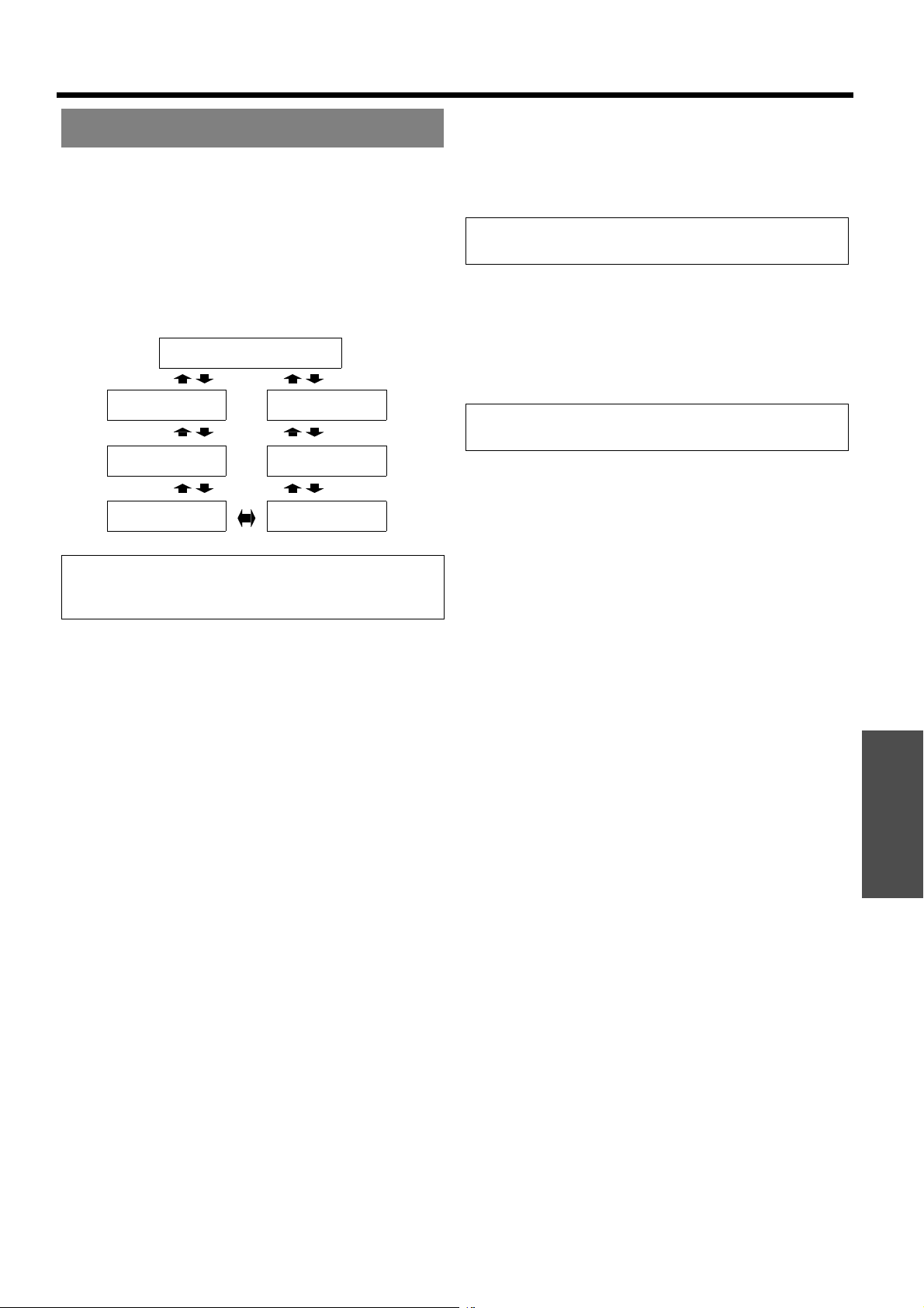
DETAILED SETUP
You can perform more detailed image adjustment
manually.
J For S-VIDEO/VIDEO signals
Q TV-SYSTEM
When the video signal is changed, the setting
switches automatically. You can switch the setting
manually to match the video data. Press I H to
cycle through the options.
AUTO
PICTURE menu
Q STILL MODE
You can reduce the vertical flicker when projecting
a still image.
OFF: Deactive
ON: Active
NOTE:
•Set to OFF when projecting a moving image.
Q NOISE REDUCTION
You can switch the automatic noise reduction
system on/off. Press I H to select the required
setting.
ON: Automatic noise reduction
OFF: No noise reduction
NTSC
NTSC 4.43
PAL
SECAM
PAL-N
PAL-M
NOTE:
• AUTO setting will select from NTSC/NTSC 4.43/PAL/
PAL60/PAL-M/PAL-N/SECAM.
NOTE:
• Applying noise reduction may affect image quality.
J For RGB signals
Q WHITE BALANCE
You can adjust the white balance more properly in
3 colours temperature by pressing I H.
WHITE BALANCE RED
WHITE BALANCE GREEN
WHITE BALANCE BLUE
Settings
ENGLISH - 33
Page 34
POSITION menu
Remote control Control panel
See “Navigating through the MENU” on page 29.
See “Main menu and Sub-menu” on page 30.
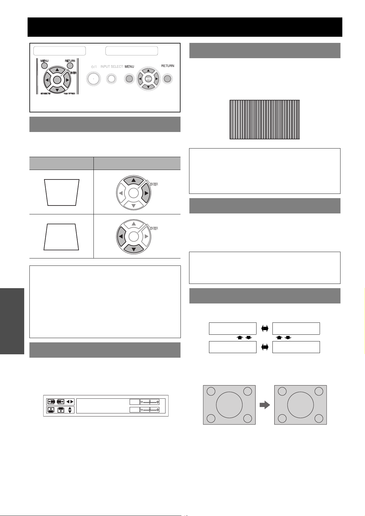
KEYSTONE
If the projector is aligned non-perpendicularly to the
screen, or if the projection screen has an angled surface,
you can correct keystone.
Image Operation
DOT CLOCK
If you have interference patterns of the projected image,
which is sometimes referred to as moire or noise, you
can minimize it by pressing I H to adjust the clock
frequency. (Available with signals from COMPUTER
only)
NOTE:
• If the projecting signal’s dot clock frequency is higher
than 108 MHz, the adjustment may not make a
difference.
• DOT CLOCK needs to be adjusted before adjusting the
CLOCK PHASE.
CLOCK PHASE
If you require further adjustment for the same reason as
the DOT CLOCK adjustment, you can fine adjust the
timing of the clock. Press I H to adjust. (Available with
signals from COMPUTER/COMPONENT only)
NOTE:
• You can correct the distortion ± 30 degrees from the
plane. For a better quality image, installing the projector
with a minimum of distortion is recommended.
Settings
• Some distortion may be retained for lens shift
adjustment.
• The distortion of the Main menu screen is not
correctable.
• The result of the keystone correction will affect the
aspect ratio and the size of the image.
POSITION
You can move the projected image for fine adjustment.
Press I H to move horizontally and F G vertically.
(Available with signals from VIDEO/S-VIDEO/
COMPUTER/COMPONENT only)
POSITION
H
V
NOTE:
• If the projecting signal’s dot clock frequency is higher
than 108 MHz, the adjustment may not make a
difference.
ASPECT
You can switch the aspect ratio manually when needed.
Press I H to cycle through the options.
4:3
16:9
Q 4:3
The input signal will be projected without any
change.
AUTO
S4:3
ENGLISH - 34
Page 35
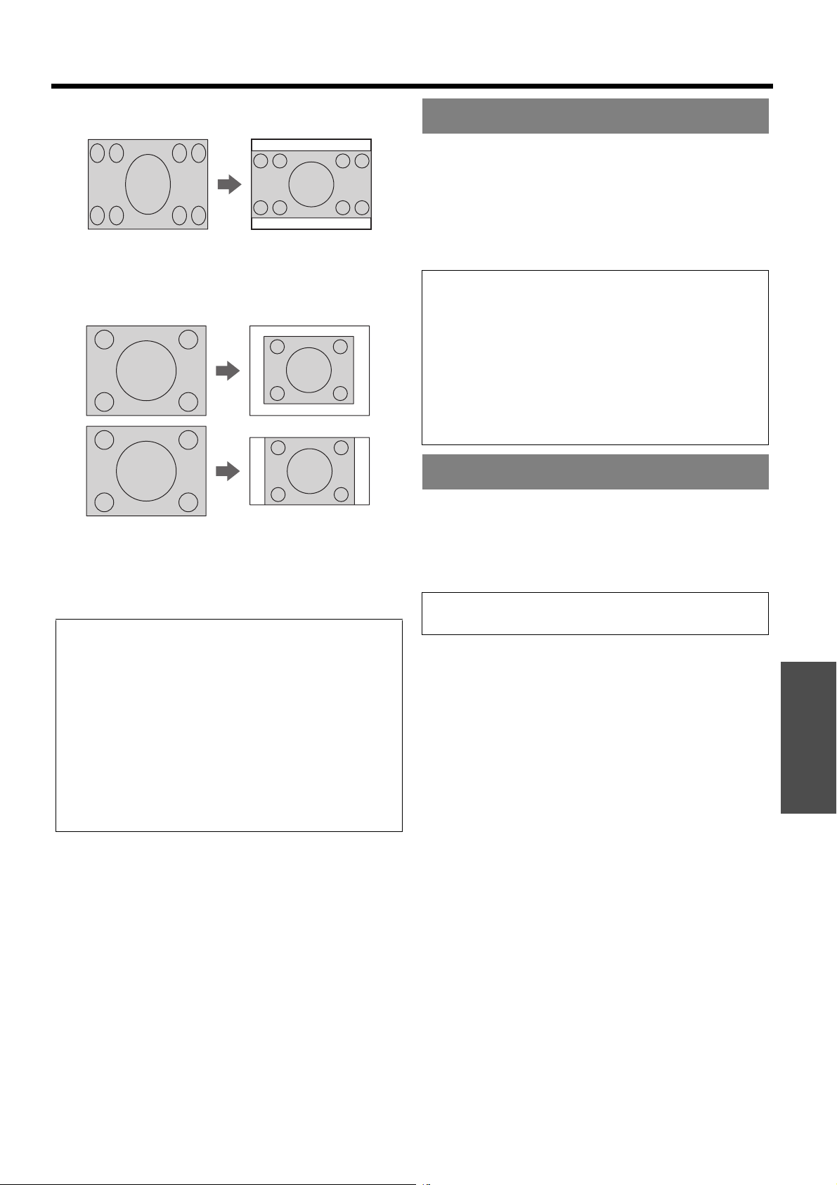
Q 16:9
The squeezed signal will be projected in 16:9 ratio.
Q S4:3
The input signal will be sized down 75 % and
projected. S4:3 mode is effective when projecting
4:3 image on to a 16:9 screen.
POSITION menu
RESIZING
When the input signal resolution is lower than the
projector resolution, it will be projected at the projector
resolution. You can deactivate the RESIZING and
project the lower resolution input signal at its original
resolution. Press I H to select the required setting.
ON Active
OFF Deactive
NOTE:
• Usually the recommended setting is ON.
• When the RESIZING is set to ON, the lower resolution
input signal may be projected in less quality.
When the RESIZING is set to OFF;
• The size of the image will be projected smaller and you
may need to adjust ZOOM and FOCUS, or the
projector position backwards and forwards.
• DIGITAL ZOOM, KEYSTONE and INDEX-WINDOW
are not available.
FRAME LOCK
Q AUTO
The S1 signal which contains an identifying signal
will be detected and automatically project the
image in proper ratio.
NOTE:
• If you project an image with an unmatched aspect ratio,
the image may distort or some portions may be
cropped. Select an aspect ratio which preserves the
intention of the image creator.
• The order of ASPECT types is defined not only by the
input method but also by the input signals. See “List of
compatible signals” on page 46.
• If you project a copyrighted image enlarged or distorted
by using ASPECT function in commercial use in a
public place, such as a restaurant or hotel, you might
infringe on the copyright of the creator which is
protected by copyright law.
If the projected image is degraded, you can activate
FRAME LOCK for synchronisation. Press I H to select
the required option.
OFF Deactive
ON Active
NOTE:
• This function is available with COMPUTER signals only.
Settings
ENGLISH - 35
Page 36
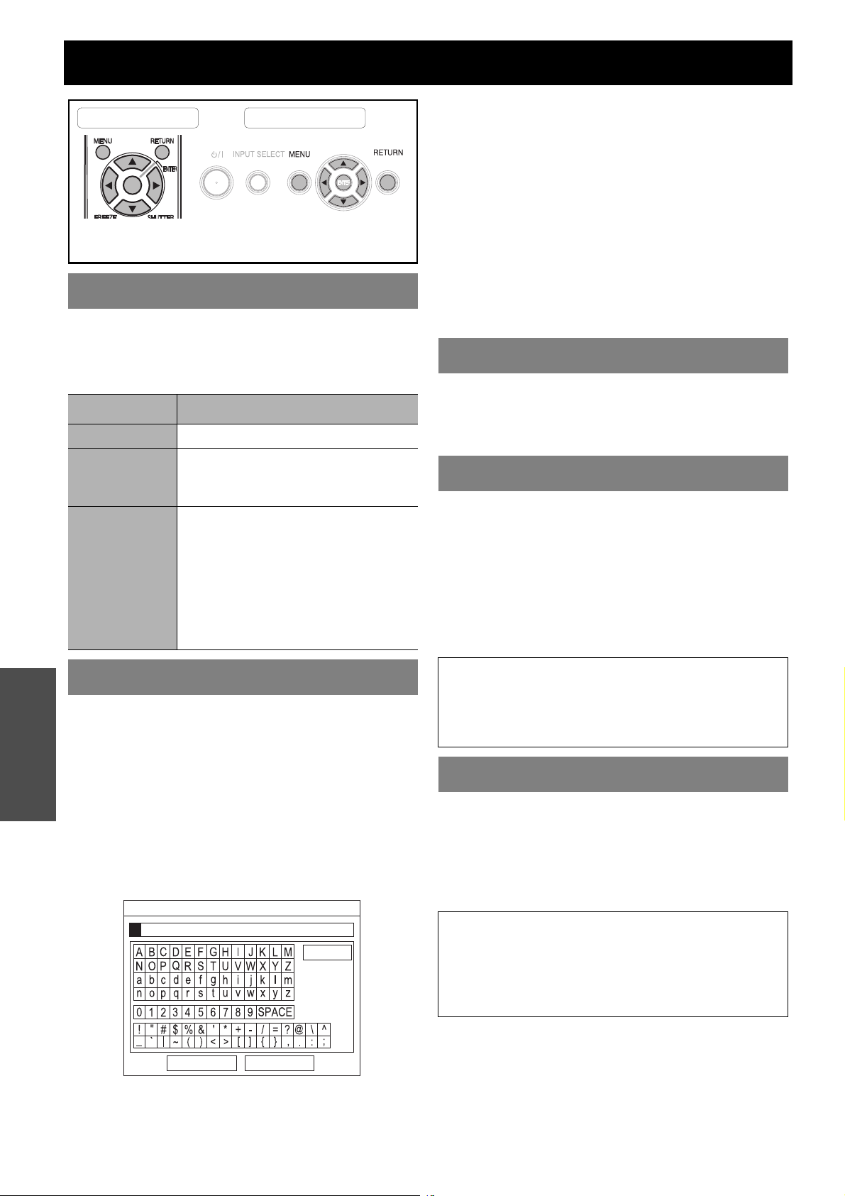
OPTION menu
Remote control Control panel
See “Navigating through the MENU” on page 29.
See “Main menu and Sub-menu” on page 30.
INPUT GUIDE
When you change the input method, the guidance
appears in the upper right corner of the screen. The
following display methods are available. Press I H to
cycle through the options.
Options Function
OFF Turn off the guidance.
Display the input method by text.
SIMPLE
DETAILED
The INPUT GUIDE will go out after
5 seconds without any operation.
Display the input method by graphic.
The INPUT GUIDE will go out after
10 seconds without any operation.
If you select any COMPUTER
terminal which has no signal, the
computer connection guidance will
be displayed. See “Computer
connection guidance” on page 48.
1. Select USER and press ENTER.
2. Select the required line to enter or edit the original
text, and press ENTER.
3. Use F G I H to specify the location of the
required character and press ENTER.
The selected character will be displayed in the box.
Select DELETE to delete the last entered character
and press ENTER.
4. Repeat the step 3 until you finish the text to display
in a line.
5. Select OK and press ENTER to set the entered
text in a box.
Press G and edit the TEXT2 if you need to, and
repeat the step 3 - 5.
COMPUTER2 SELECT
You can switch the function of the COMPUTER2 IN/
1OUT terminal.
INPUT COMPUTER2 IN
OUTPUT COMPUTER1 OUT
FILTER SETUP
You can change the pace of the ARF (Auto Rolling Filter)
performance for the use environment. Press I H to
select the required option.
1 Ventilated with indoor air (e.g. small
office room)
2 Ventilated with outdoor air (e.g. large
office room, class room)
3 Public indoor space (e.g. restaurant,
building lobby)
STARTUP LOGO
Settings
You can switch the logo on/off that is displayed when
starting up the projector. Press I H to select the
required option. STARTUP LOGO will be displayed for
30 seconds.
ON Active
OFF Deactive
USER Display the original text
Q Editing the original text
If you select USER, you can display the 2 lines of
original text up to 40 characters in 1 line instead of
the logo.
TEXT CHANGE
DELETE
OK CANCEL
NOTE:
•The ARF is a nonreusable product.
• Select the most suitable option for the use environment.
• If you select an unsuitable option, it may greatly affect
on the duration of the projector life.
FILTER REMAINING
You can check the remaining amount of the ARF (Auto
Rolling Filter). The colour of the bar scale is indicating
the condition of the ARF.
Yellow The filter remaining amount is getting
low.
Red No more remaining.
NOTE:
• See “Replacing the ARF (Auto Rolling Filter)” on
page 42.
• After you replace the ARF, FILTER REMAINING should
be reset to “0” by pressing the ENTER button for
3 seconds.
ENGLISH - 36
Page 37
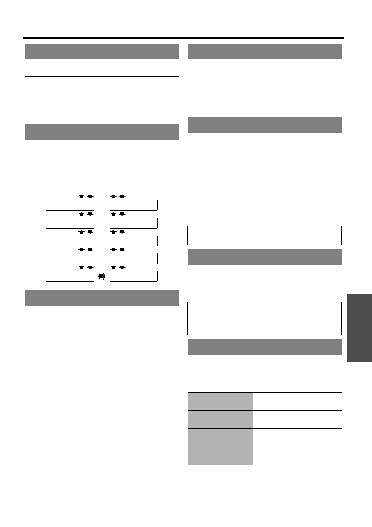
OPTION menu
LAMP RUNTIME
You can check how long the lamp has been used.
NOTE:
• LAMP RUNTIME is a relevant matter for lamp
replacement timing. See “Replacing the Lamp unit” on
page 43.
• When the lamp unit is replaced with the new one
(ET-LAF100), the setting will be reset to “0”.
POWER OFF TIMER
You can set the off timer to switch off the POWER of the
projector after a certain period of time automatically
when no signal is detected. Press I H to select the
required period from 15 to 60 minutes at intervals of
5 minutes.
DISABLE
15 MIN.
20 MIN.
25 MIN.
60 MIN.
55 MIN.
50 MIN.
CONTROL PANEL
You can turn off the function of the control panel buttons
on the projector body. Press I H to select the required
option.
INVALID Invalidate the control panel buttons
Confirmation screen will be
displayed.
VALID Validate the control panel buttons
AUTO SETUP
You can turn off the AUTO SETUP function for when the
COMPUTER signal is detected.
AUTO When the projector detect a
COMPUTER signal, adjust the
projected image position
automatically for SIGNAL SEARCH,
DOT CLOCK and CLOCK PHASE.
BUTTON Only when the AUTO SETUP button
is pressed, the projected image
position will be adjusted for DOT
CLOCK and CLOCK PHASE. See
“Remote control” on page 13.
NOTE:
• Usually the recommended setting is AUTO.
30 MIN.
35 MIN.
45 MIN.
40 MIN.
DIRECT POWER ON
You can switch the projector start up status for when the
Mains lead is connected while the MAIN POWER is on,
or for when the MAIN POWER is switched on while the
Mains lead is connected. Press I H to select the
required option.
OFF The projector will start from the
standby mode or the projecting
mode.
ON The projector will start from the
projecting mode.
NOTE:
• When the projector is started from the projecting mode,
pressing the POWER button procedure is skippable.
SIGNAL SEARCH
You can turn off the auto signal detecting system.
ON Detect the input signal from the
terminals and project the image.
OFF Deactive
NOTE:
• SIGNAL SEARCH is not available when any input
signal is projecting.
• Usually the recommended setting is ON.
INSTALLATION
When installing the projector, select the projection
method according to the projector position. Press I H
to cycle through the options. See “Projection method” on
page 17.
FRONT/DESK
FRONT/CEILING
REAR/DESK
REAR/CEILING
Setting on a desk/floor and
projecting from front
Mounting in the ceiling and
projecting from front
Setting on a desk/floor and
projecting from rear
Mounting in the ceiling and
projecting from rear
Settings
ENGLISH - 37
Page 38
OPTION menu
HIGHLAND
If you use the projector at high elevation, the HIGHLAND
setting need to be ON to set the fan speed high. Press
I H to select the required option.
OFF The fan speed is low.
ON The fan speed is high.
NOTE:
• At 1 400 m (4 593 ft) above sea level, the setting must
be ON.
• The loudness of fan noise depends on the HIGHLAND
setting.
TEST PATTERN
You can use the 7 different test patterns to adjust the
focus of the image. See “Lens shift and positioning” on
page 18.
1. Press ENTER to display the test pattern 1.
2. Press I H to select the required test pattern.
3. Adjust the focus with the Focus lever.
4. Press MENU or RETURN to return to the previous
menu, oar press repeatedly to escape the menu
mode.
J XGA MODE
You can switch the setting between XGA and the
wider setting, WXGA. Press I H to select the
required option.
J BLACKBOARD
You can exclude the BLACKBOARD in menu
items of PICTURE MODE in PICTURE menu.
Press I H to select the required option.
ON Include the BLACKBOARD in menu
items.
OFF Exclude the BLACKBOARD in menu
items.
J BACK COLOUR
You can choose a BLUE or BLACK screen for
when the projector is idle. Press I H to select the
required option.
J VOLUME
You can adjust the volume of the built-in monaural
speaker and VARIABLE AUDIO OUT terminal.
I Decrease
H Increase
J AUDIO BALANCE
NOTE:
• When the projector and/or the screen is tilted, adjust
the focus at the centre of the image. The upper and
lower edge might be out of focus.
• When the image is distorted in keystone, adjust the
KEYSTONE in POSITION menu.
DETAILED SETUP
Settings
You can perform more detailed setting in various items.
J OSD DESIGN
You can change the background colour of the
menu. Press I H to select the required option.
TYPE1 Semi transparent black
TYPE2 Solid blue
TYPE3 Semi transparent dark blue
J SXGA MODE
You can switch the setting between SXGA and the
larger setting, SXGA+. Press I H to select the
required option.
You can adjust to hear the sound played equally
through both right and left external stereo
speakers, or shift the balance so more sound plays
through the left or right side.
I More sound plays through the left
side
H More sound plays through the right
side
J INITIALISE ALL
You can reset all of the customised settings to the
factory defaults except NETWORK, LAMP
RUNTIME and FILTER REMAINING menu
settings.
You can reset all of the customised settings to the
factory defaults except LAMP RUNTIME and
FILTER REMAINING menu settings.
1. Press the ENTER button
2. Turn off the projector by pressing the POWER
button.
3. Switch off the MAIN POWER button to reset the
projector.
4. The minimum required setting screen will be
displayed.
See “Minimum required setting screen” on page 12.
ENGLISH - 38
Page 39
SECURITY menu
Remote control Control panel
See “Navigating through the MENU” on page 29.
See “Main menu and Sub-menu” on page 30.
J Entering the SECURITY menu
Every time when you apply to the SECURITY
menu, you will be asked to perform the password
operation.
PICTURE
POSITION
LANGUAGE
OPTION
SECURITY
NETWORK
SELECT
INPUT PASSWORD
PASSWORD CHANGE
TEXT DISPLAY
TEXT CHANGE
PASSWORD
RETURN
ENTER
OFF
OFF
PASSWORD CHANGE
You can change the password operation to your original.
1. Press a series of button operation up to 8 as a
password by using F G I and H buttons.
2. Press ENTER.
3. Press the exact same series of button operation
you entered in the NEW password box for
confirmation.
If a series of button operation is incorrect, you will be
asked to perform again.
4. Press ENTER.
NOTE:
• The entered password operations will appear as
asterisks in the box.
TEXT DISPLAY
You can set your original text, such as company name or
URL information, to display regularly at the bottom of the
projected image while projecting.
OFF Deactive
ON Active
When you apply to the SECURITY menu before you
change the password to your original, perform to input
the following factory default password operation.
Press F H G I F H G I and ENTER.
Q After you change the password
When you apply to the SECURITY menu after you
change the password to your original in the
PASSWORD CHANGE menu, input the original
password operation.
NOTE:
• The factory default password is valid until you change
the password in PASSWORD CHANGE menu.
• The entered password operations will appear as
asterisks in the box.
INPUT PASSWORD
You can activate the security system and the password
operation will be asked to perform when the projecting
mode started. Unless you perform the correct password
operation, all of the button controls will be disabled
except the POWER button.
OFF Deactive
ON Active
TEXT CHANGE
You can enter your original text up to 22 characters for
TEXT DISPLAY.
TEXT CHANGE
DELETE
OK CANCEL
1. Use F G I H to specify the location of the
required character.
2. Press ENTER.
The selected character will be displayed in the TEXT
CHANGE box.
3. Repeat until finish your original text.
Select DELETE to delete the last entered character
and press ENTER.
4. Select OK and press ENTER to set the entered
text.
Select CANCEL or press MENU/RETURN buttons to
return to the previous menu.
Settings
NOTE:
• When you activated the security system, make sure to
change the password to your original for safety.
• The factory default password is valid until you change
the password in PASSWORD CHANGE menu.
ENGLISH - 39
Page 40
NETWORK menu
Remote control Control panel
See “Navigating through the MENU” on page 29.
See “Main menu and Sub-menu” on page 30.
NOTE:
• The NETWORK menu is available only with
PT-F100NTE.
• See more detailed instructions in the contents of the
CD-ROM which is provided with the projector.
Items in NETWORK menu
In NETWORK menu, the following items are available.
WIRED LAN
WIRELESS LAN
NAME CHANGE
INPUT PASSWORD
PASSWORD CHANGE
NETWORK STANDBY
WEB CONTROL
LIVE MODE CUT IN
STATUS
INITIALISE
Settings
ENGLISH - 40
Page 41
TEMP, LAMP and FILTER Indicators
Managing the indicated problems
If a problem should occur with the projector, the TEMP, LAMP and/or
FILTER indicators will inform you. Manage the indicated problems as
follow.
1. Confirm the status of all indicators and projector, and switch off the
projector in proper way.
2. Find out the cause of the problem by status of the TEMP, LAMP
and/or FILTER indicators.
3. Follow the instruction for each indication below and solve the
problem.
4. Turn on the projector in the correct way and confirm the indicator is
not indicating a problem any longer.
POWER
LAMP
TEMP
NOTE:
• If no problem is found or the problem remains, do not turn on the projector. Instead contact an Authorised Service Centre.
J LAMP indicator
Indicator
Problem
Cause
Remedy
Illuminating RED Flashing RED
LAMP RUNTIME has
reached 2 800 hours.
Lamp unit will run out
soon and needs to be
replaced.
See “Replacing the
Lamp unit” on page 43.
LAMP circuit failure, abnormal function or Lamp unit is damaged.
The MAIN POWER is
switched on again
before the Lamp unit
is cooled enough.
Let the Lamp unit cool
down and turn on the
MAIN POWER.
LAMP circuit failure,
abnormal function.
Contact an Authorised
Service Centre.
Lamp unit is
damaged.
See “Replacing the
Lamp unit” on page 43.
FILTER
J TEMP indicator
Indicator
Problem The temperature inside and/or outside the projector is abnormally high.
Cause
Remedy
*1. The projector will perform only 2 minutes with OFF setting at high elevation.
Illuminating RED and still projecting
Flashing RED and POWER is turned off
The ventilation
openings are covered.
Remove the object(s)
from the ventilation
openings or clear
around the projector.
The room temperature
is too high.
Reinstall the projector
in temperature
controlled place. See
page 50.
The ARF is excessively
dirty and the ventilation
is poor.
Replace the ARF in the
proper method. See
page 42.
J FILTER indicator
When the FILTER indicator is flashing GREEN, the ARF is normally rolling up.
Indicator
Problem
Cause ARF has been run out. ARF is not attached.
Remedy
Illuminating RED Flashing RED Illuminating ORANGE Flashing ORANGE
FILTER REMAINING
has turned red. See
page 36.
See “Replacing the
ARF (Auto Rolling
Filter)” on page 42.
The projector cannot
detect the ARF.
Attach the ARF.
The ARF cannot
operate properly.
Foreign object is
blocking the ARF
operation.
Remove the foreign
object or contact an
Authorised Service
Centre.
The projector is located
at high elevations
(above 1 400 m).
Turn on the projector
and set the
HIGHLAND to ON.
See page 38.
FILTER REMAINING
has turned yellow. See
page 36.
ARF is running out.
Prepare the ARF for
replacement.
*1
Maintenance
ENGLISH - 41
Page 42
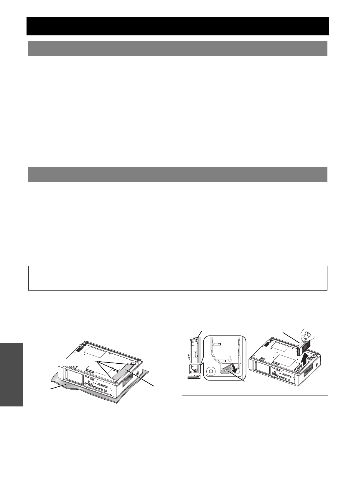
Care and Replacement
Cleaning the projector
J Before cleaning the projector
Switch off the MAIN POWER and disconnect the mains plug from the mains socket.
Unplug all the cables from the projector.
J Cleaning the outer surface of the projector
Wipe off dirt and dust gently with a soft cloth.
If it is difficult to remove the dirt, soak a cloth in a neutral detergent diluted with water, wring the cloth well
and then wipe the projector. Dry off the projector with dry cloth.
If you use a chemical treated wipe, follow the instructions supplied with it.
J Cleaning the lens and front glass surface
Wipe off dirt and dust gently with a lint-free cloth.
Make sure no dirt or dust remains on the surface of the lens. It will be enlarged and projected onto a
screen.
Replacing the ARF (Auto Rolling Filter)
J Before replacing the ARF
Press the POWER button for at least 0.5 seconds or press twice to turn off the projector.
Wit until the cooling fan stops and the POWER indicator turn to RED.
Disconnect the Mains lead from the main socket.
Prepare a Phillips-head screw driver.
Contact an Authorised Service Centre to purchase a replacement ARF (ET-RFF100).
J When to replace the ARF
ARF is consumable product and effects on ventilation. FILTER indicator will inform you of the replacement
timing. You can check the remaining amount of the ARF in FILTER REMAINING menu.
NOTE:
• See “FILTER REMAINING” on page 36.
• See “FILTER indicator” on page 41.
J Replacement procedure
1. Turn the projector upside down and place it gently
on a soft cloth.
2. Use a Phillips-head screwdriver to loosen 3 ARF
cover fixing screws until the screws turn freely and
remove the ARF cover.
Maintenance
ARF cover fixing screw
Soft cloth
3. Use a Phillips-head screwdriver to loosen an ARF
fixing screws and release the clamp, then slightly
slide up the used ARF to remove.
4. Insert the new ARF into the compartment in
correct direction and slightly push down until it
clicks. Tighten the ARF fixing screws securely with
a Phillips-head screwdriver.
ARF cover
5. Attach the ARF cover and tighten the ARF cover
fixing screws securely with a Phillips-head
screwdriver.
ARF fixing screw
PUSH
押す
ARF
Clamp
NOTE:
• If the ARF and/or ARF cover are attached incorrectly,
the projector may not be turned on.
• Do not switch the power on while the ARF cover
removed.
• When you replace the ARF unit, clean the compartment
and/or the Air Exhaust port if you need to.
ENGLISH - 42
Page 43
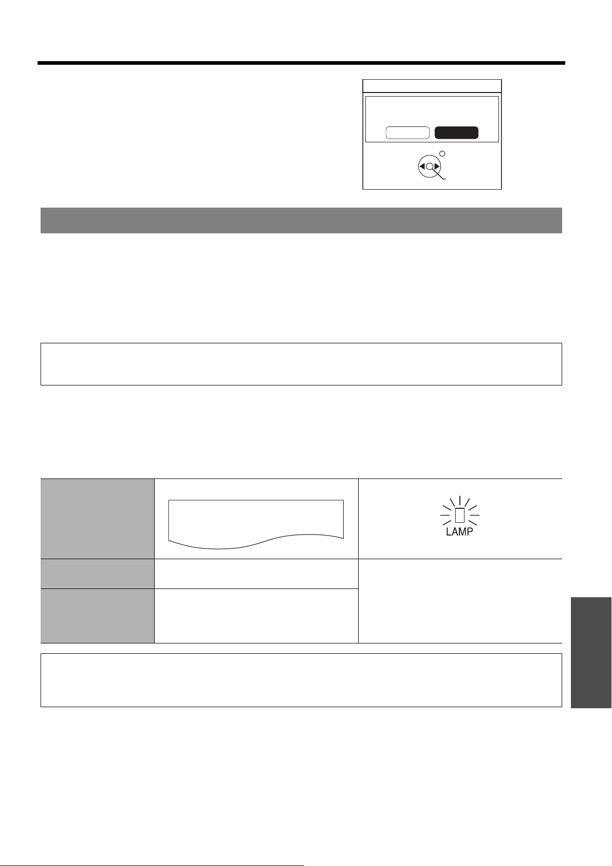
Care and Replacement
J Resetting the FILTER
REMAINING
FILTER REMAINING
1. Turn on the projector and display the FILTER
REMAINING in OPTION menu. Press the ENTER
button for 3 seconds and the confirmation screen
will be displayed.
2. Press I to select OK and press the ENTER
button to reset FILTER REMAINING to “0”.
“FILTER REMAINING” on page 36.
See
RESET A REMAIN OF A FILETER.
OK CANCEL
RETURN
SELECT
ENTER
Replacing the Lamp unit
J Before replacing the Lamp unit
Switch off the MAIN POWER and disconnect the mains plug from the mains socket.
Make sure the Lamp unit and the surroundings are cooled enough.
Prepare a Phillips-head screwdriver.
Contact an Authorised Service Centre to purchase a replacement Lamp unit (ET-LAF100).
When the projector is mounted in the ceiling, do not work directly under the projector or put your face closer
to the projector.
NOTE:
• Prior to replacing the lamp unit, allow it to cool down to prevent the risk of burns, damage and other hazards.
• Do not attempt replacement with an unauthorised lamp unit.
J When to replace the Lamp unit
The Lamp unit is consumable and the brightness decreases by duration of usage. The LAMP indicator will
inform you of the replacement timing at 2 800 hours, and at 3 000 hours, the projector will be turned off. Those
figures are rough guidance and might be shortened by the usage conditions, characteristics of the Lamp unit,
environmental conditions, and so on. You can check the duration of usage time using LAMP RUNTIME in the
OPTION menu.
On screen
Indication
Over 2 800 hours
Over 3 000 hours
REPLACE LAMP
“REPLACE LAMP” is displayed on the
upper left of the screen for 30 seconds.
“REPLACE LAMP” is displayed on the
upper left of the screen, and it will stay until
you respond.
To clear the screen, press any button.
NOTE:
• The guide times, 2 800 and 3 000 hours, are rough estimates based on certain conditions and is not a guaranteed time.
• For more information about the Lamp unit, such as guaranteed time, see the instructions which is provided with the
Lamp unit.
LAMP indicator
Illuminates RED.
Maintenance
ENGLISH - 43
Page 44
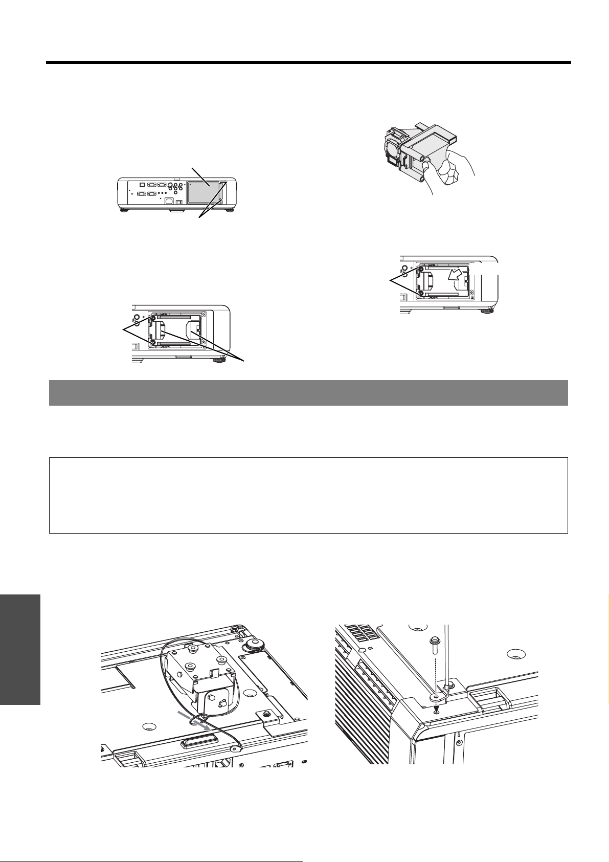
Care and Replacement
J Replacement procedure
Q Removing and replacing the lamp unit
1. Use a Phillips-head screwdriver to loosen the 2
Lamp unit cover fixing screws on the back of the
projector until the screws turn freely, and remove
the Lamp unit cover.
Lamp unit cover
Lamp unit cover fixing screws
2. Use a Phillips-head screwdriver to loosen the 2
Lamp unit fixing screws.
3. Hold the handles of the Lamp unit and release the
lamp unit lock.
4. Pull the used Lamp unit gently from the projector.
5. Replace the new Lamp unit in correct direction.
6. Press in the Lamp unit until it clicks and make
sure the unit is installed securely.
7. Tighten the 2 Lamp unit fixing screws securely
with a Phillips-head screwdriver.
Lamp unit
fixing screws
Press here
Lamp unit
fixing screws
Handles
8. Attach the Lamp unit cover and tighten the 2
Lamp unit cover fixing screws securely with a
Phillips-head screwdriver.
LAMP RUNTIME will be reset to “0” automatically.
Ceiling mount bracket safeguards
The projector and the ceiling mount bracket are designed sufficiently safety though, make sure the safety cable
provided with the projector is installed and attached to the bottom of the projector when mounting in the ceiling for
safety and security.
NOTE:
• Even if it is guarantee period, the manufacturer is not responsible for any hazard or damage caused by using a ceiling
mount bracket which is not purchased from an authorised distributors, or environmental conditions.
• Make sure to use a torque driver and do not use an electrical screwdriver or an impact screwdriver.
• Installation work of the ceiling mount bracket should only be carried by a qualified technician.
• Remove an unused ceiling mount bracket promptly.
J Installing the safety cable
1. Install the ceiling mount bracket according to the installation instructions.
2. Loop the security cable around the ceiling mount bracket with less slack.
Lace the cable of the end with a latch through the loop on the other end of the cable.
Maintenance
3. Attach the latch on to the bottom of the projector with a provided screw.
Torque: 1.25±0.2 N·m
* Indicated above is ET-PKF100S.
ENGLISH - 44
Page 45
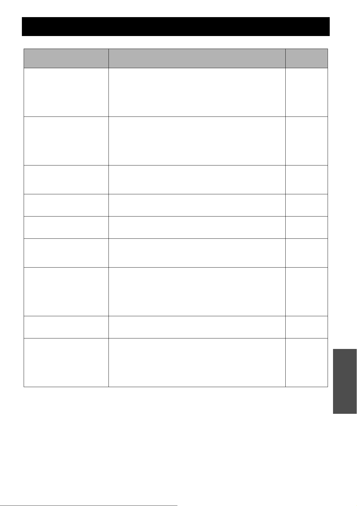
Troubleshooting
Should any problem persist, contact your dealer.
Problem Cause
Power does not turn on.
No picture appears.
The picture is fuzzy.
The colour is pale or
greyish.
No sound can be heard
from the internal speaker.
The control buttons of the
projector do not operate.
The Remote control does
not operate.
The picture does not
display correctly.
Picture from a computer
does not appear.
The mains lead may not be connected.
The MAIN POWER switch is turned off.
No electric supply is at the mains socket.
TEMP indicator is lit or flashes.
LAMP indicator is lit or flashes.
The lamp unit cover has not been securely installed.
The circuit breakers have tripped.
The video signal input source may not be connected to a terminal
properly.
The input selection setting may not be correct.
The BRIGHTNESS adjustment setting may be at the minimum setting.
The signal input source may not be operating properly.
The SHUTTER function may be in use.
The ARF is removed or installed incorrectly.
The lens focus may not have been set correctly.
The projector may not be at the correct distance from the screen.
The lens may be dirty.
The projector may be tilted too much.
COLOUR or TINT adjustment may be incorrect.
The input source which is connected to the projector may not be
adjusted correctly.
The audio signal source may not be connected properly.
A cable may be connected to the VARIABLE AUDIO OUT terminal.
The volume adjustment may be at the lowest possible setting.
CONTROL PANEL in OPTION menu is invalidated. If you have a loss
of the Remote control while the CONTROL PANEL is invalidated,
press and hold the MENU button for 2 seconds with pressing the
ENTER button.
The batteries may be weak.
The batteries may not have been inserted correctly.
The remote control signal receptor on the projector may be
obstructed.
The remote control unit may be out of the operation range.
The Remote control is under the strong light such as fluorescent.
The LASER button is deactivated.
The signal format (TV-SYSTEM) may not have been set correctly.
There may be a problem with the VCR or other signal source.
A signal which is not compatible with the projector is being input.
The cable may be longer than the optional cable.
The external video output from a laptop computer may not be correct.
(You may be able to change the external output settings by pressing
the [Fn] + [F3] or [Fn] + [F10] keys simultaneously. The actual method
varies depending on the type of computer; refer to the documentation
provided with your computer for further details.)
COMPUTER2 SELECT setting in OPTION menu is not correct.
Reference
page
22
23
22
41
41
44
-
21
26
32
27
42
24
16
11
18
32
30
20
15
28
37
13
25
25
25
26
33
46
48
36
ENGLISH - 45
Maintenance
Page 46
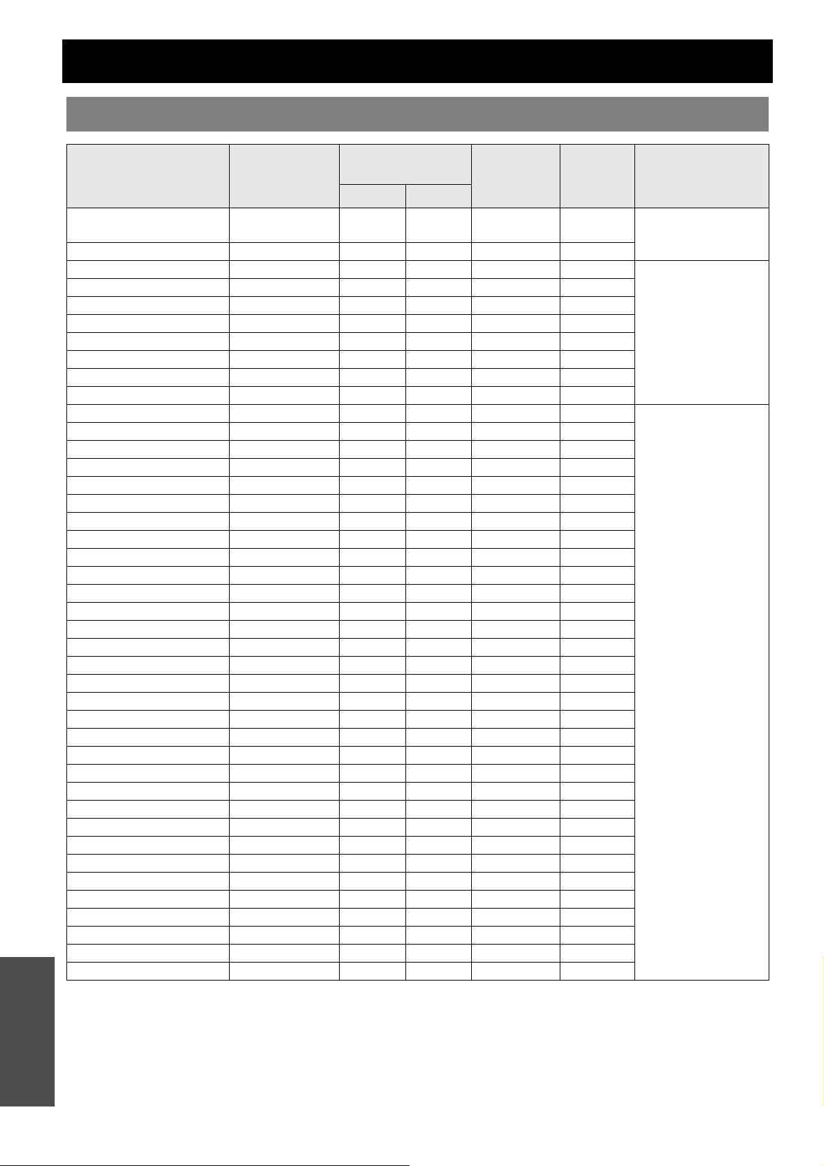
Technical Information
List of compatible signals
NTSC/NTSC 4.43/
PAL/PAL-N/SECAM 720 x 576i 15.6 50.0 A
Appendix
*1. The “i” appearing after the resolution indicates an interlaced signal.
*2. The following symbols are used to indicate picture quality.
*3. YP
Display
Mode
PAL-M/PAL60
480i 720 x 480i 15.7 59.9 13.5 A
576i 720 x 576i 15.6 50.0 13.5 A
480p 720 x 483 31.5 59.9 27.0 A
576p 720 x 576 31.3 50.0 27.0 A
1 080/60i 1 920 x 1 080i 33.8 60.0 74.3 A
1 080/50i 1 920 x 1 080i 28.1 50.0 74.3 A
720/60p 1 280 x 720 45.0 60.0 74.3 A
720/50p 1 280 x 720 37.5 50.0 74.3 A
VESA 640 x 400 31.5 70.1 25.2 A
VGA480 640 x 480 31.5 59.9 25.2 A
SVGA 800 x 600 35.2 56.3 36.0 A
MAC 832 x 624 49.7 74.6 57.3 A
XGA 1 024 x 768 48.4 60.0 65.0 AA
MXGA 1 152 x 864 64.0 71.2 94.2 A
MSXGA 1 280 x 960 60.0 60.0 108.0 A
SXGA 1 280 x 1 024 64.0 60.0 108.0 A
SXGA60+ 1 400 x 1 050 64.0 60.0 108 A
UXGA 1 600 x 1 200 75.0 60.0 162.0 A
WXGA 1 280 x 768 47.8 59.9 79.5 A
WXGA+ 1 440 x 900 55.9 59.9 106.5 A
AA Maximum picture quality can be obtained.
A Signals are converted by the image processing circuit before picture is projected.
BPR signals are available with COMPONENT terminal, and RGBHV signals are available with COMPUTER terminal.
resolution
*1
(dots)
720 x 480i 15.7 59.9 A
640 x 400 37.9 85.1 31.5 A
640 x 480 35.0 66.7 30.2 A
640 x 480 37.9 72.8 31.5 A
640 x 480 37.5 75.0 31.5 A
640 x 480 43.3 85.0 36.0 A
800 x 600 37.9 60.3 40.0 A
800 x 600 48.1 72.2 50.0 A
800 x 600 46.9 75.0 49.5 A
800 x 600 53.7 85.1 56.3 A
1 152 x 870 68.7 75.1 100.0 A
1 024 x 768 56.5 70.1 75.0 AA
1 024 x 768 60.0 75.0 78.8 AA
1 024 x 768 68.7 85.0 94.5 AA
1 152 x 864 67.5 74.9 108.0 A
1 152 x 864 76.7 85.0 121.5 A
1 280 x 1 024 80.0 75.0 135.0 A
1 280 x 1 024 91.1 85.0 157.5 A
1 400 x 1 050 65.1 59.9 122.4 A
1 280 x 800 49.1 60.2 69.1 A
1 280 x 800 49.7 59.8 83.5 A
Scanning
frequency
H (kHz) V (kHz)
Dot clock
frequency
(MHz)
Picture
quality
*2
Terminals
VIDEO/S-VIDEO
COMPONENT/
COMPUTER
COMPUTER
*3
ENGLISH - 46
Page 47
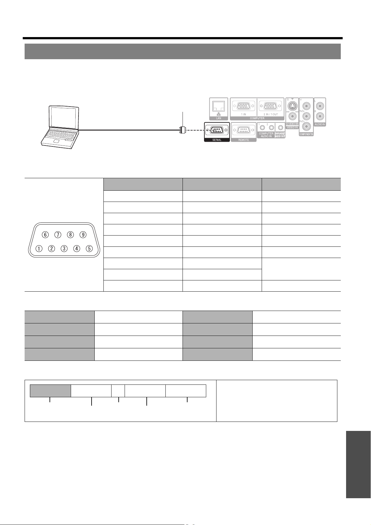
Technical Information
Serial terminal
The serial connector which is on the connector panel of the projector conforms to the RS-232C interface
specification, so that the projector can be controlled by a personal computer which is connected to this connecter.
J Connection
D-sub 9 pin (male)
Computer
Serial terminal (female)
J Pin assignments and signal names
Pin No. Signal name Contents
A
B
C
TXD Transmitted data
RXD Received data
D
E
GND Earth
F
G
H
RTS
CTS
I
J Communication settings
Signal level RS-232C Character length 8bits
NC
NC
NC
Connected internally
NC
Sync. method Asynchronous Stop bit 1bit
Baud rate 9600bps X parameter None
Parity None S parameter None
J Basic format
STX Command : Parameter ETX
Start byte
(02h)
The projector can not receive any command for 10 seconds after the lamp is switched on. Wait 10 seconds
before sending the command.
If sending multiple commands, check that a response has been received from the projector for one
command before sending the next command.
When a command which does not require parameters to be sent, the colon (:) is not required.
If an incorrect command is sent from the personal computer, the ER401 command will be sent from the
projector to the personal computer.
3bytes
1byte End
1byte 4bytes
(03h)
The data streaming from the computer will
start with STX, and proceed to Command,
Parameter and end with ETX. You can
add the required parameter.
Appendix
ENGLISH - 47
Page 48
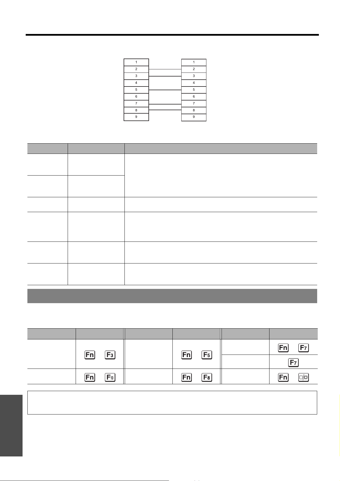
Technical Information
J Cable specifications
(When connected to a personal computer)
NC
NC
NC
NC
Projector PC (DTE)
NC
NC
NC
NC
J Control commands
Command Control contents Remarks
In standby mode, all commands other than the PON command are
PON Power ON
POF Power OFF
AVL Volum e
IIS INPUT
Q$S
OSH SHUTTER
Lamp condition
query
ignored.
The PON command is ignored during lamp ON control.
If a PON command is received while the cooling fan is operating after the
lamp has switched off, the lamp is not turned back on again straight away
in order to protect the lamp.
Parameter
000 - 063 (Adjustment value 0 - 63)
Parameter:
VID = VIDEO
RG1 = COMPUTER1
NWP = WIRELESS (PT-F100NTE only)
Call back
0 = Standby
1 = Lamp ON control active
Turning off the projection temporarily.
Send the command to switch between ON and OFF.
Do not send the command consecutively.
SVD = S-VIDEO
RG2 = COMPUTER2
2 = Lamp ON
3 = Lamp OFF control active
Computer connection guidance
You can switch the signals which to output from the COMPUTER1 OUT terminal by pressing the computer key
command. The key commands are depend on the manufactures. If you select the computer terminals which has no
signals while the INPUT GUIDE is set to DETAILED, the computer connection guidance will be displayed.
Manufacturer Key command Manufacturer Key command Manufacturer Key command
IBM
SONY
Apple
Other
Panasonic
NEC
FUJITSU
NOTE:
Appendix
• The computer connection guidance will disappear after 5 minutes.
• Please refer the instructions which provided with the computers for more detailed information.
+
+
TOSHIBA
SHARP
HP
EPSON
DELL
+
+
+
+
ENGLISH - 48
Page 49
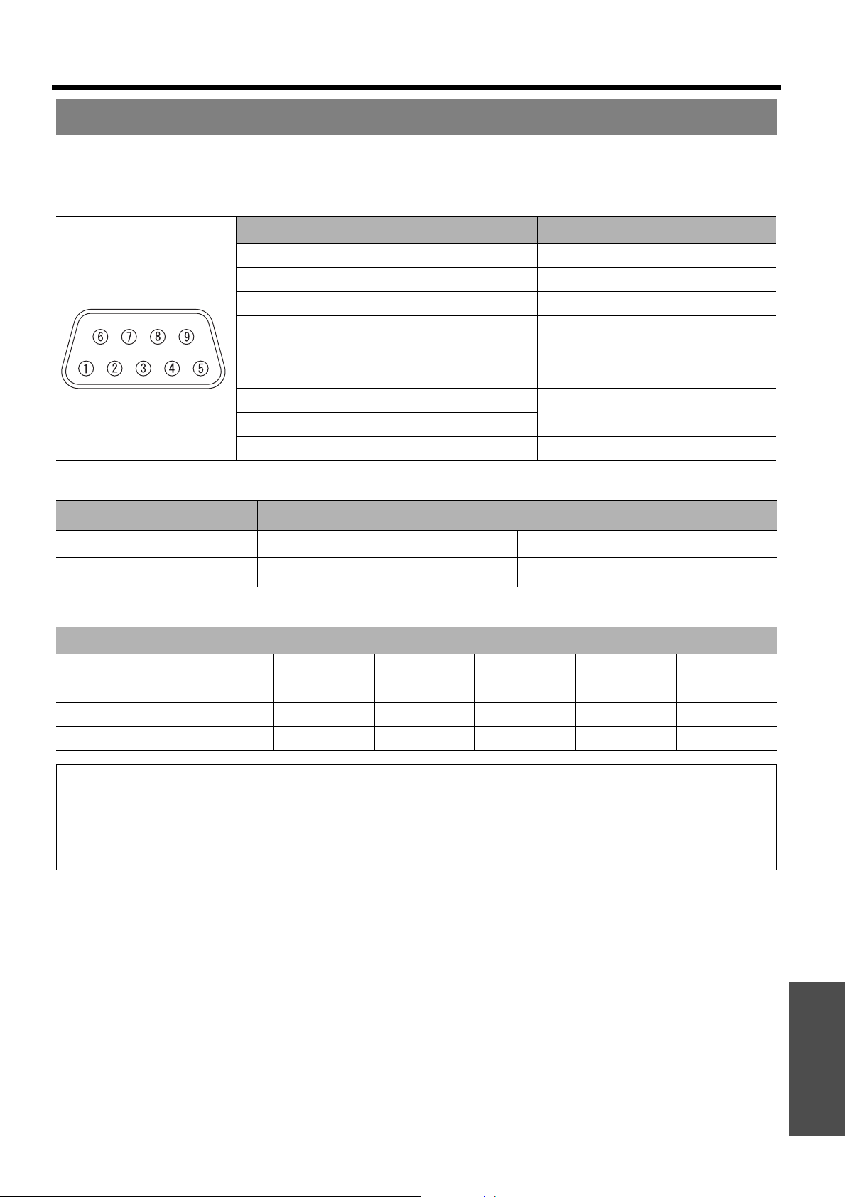
Technical Information
REMOTE terminal
You can remotely operate the projector from the outside the Remote control range by connecting to the REMOTE
terminal.
J Pin assignments and signal names
Pin No. Signal name Contents
A
B
C
POWER POWER ON
INPUT SEL3 Select input signal 3
D
E
F
INPUT SEL1 Select input signal 1
INPUT SEL2 Select input signal 2
G
H
I
ENABLE Control by external contact
J LAMP switching
Pin No. Settings
B - A
Operation On Off
Short Open
J Switching input signals
Pin No. Settings
C - A
E - A
F - A
Input signal
Open Open Short Short Short Open
Open Short Open Open Short Short
Open Open Short Open Open Short
COMPUTER1 COMPUTER2 COMPONENT VIDEO S-VIDEO NETWORK
GND Ground
NC
Connect internally
NOTE:
• When pin A and pin I are short-circuited, the buttons on the projector’s control panel, POWER and INPUT SELECT
buttons on the Remote control cannot be used. In addition, the RS-232C commands and network functions that
correspond to these functions cannot be used either.
• While pin I is “Open”, do not short-circuit pin A, B, C, E and F. The projector would reject all the signals from the
Remote control.
ENGLISH - 49
Appendix
Page 50
Technical Information
Specifications
Power supply AC 100 - 240 V 50 Hz/60 Hz
Power consumption
Amps 3.9 A - 1.4 A
Panel size (diagonal) 0.7 type (17.78 mm)
Aspect ratio 4 : 3
330 W
During standby (when fan is stopped): 3 W
LCD panel
Lens
Lamp UHM lamp (250 W)
Luminosity 3200lm
Operating environment
Scanning
frequency
(for RGB signal)
COMPONENT (YPBPR) signals 480i, 480p, 576i, 576p, 720/50p, 720/60p, 1 080/50i, 1 080/60i,
Colour system 7 (NTSC/NTSC 4.43/PAL/PAL-M/PAL-N/PAL60/SECAM)
*1
Display method 3 transparent LCD panels (RGB)
Drive method Active matrix method
Pixels 786 432 (1 024 x 768) x 3 panels
Manual zoom (2x)/Manual focus
F 1.7 - 2.6, f 21.6 mm - 43.0 mm
Temperature
Humidity 20% - 80% (no condensation)
Horizontal scanning
frequency
Vertical scanning
frequency
Dot clock frequency Less than 110 MHz
15 kHz - 91 kHz
50 Hz - 85 Hz
0°C - 40°C (32°F - 104°F)
When the HIGHLAND (page 38)
is set to ON: 0 °C - 35 °C (32 °F 95 °F)
Projection size 33" - 300" (838.2 mm - 7 620 mm)
Throw distance 1.2 m - 18.1 m (3'11" - 59'4")
Screen aspect ratio 4 : 3
Installation
Speaker 1 piece 4 cm (1 - 9/16")
Max. useable volume output 3.0 W
*1. See “List of compatible signals” on page 46 for available signals.
Appendix
FRONT/DESK, FRONT/CEILING, REAR/DESK, REAR/CEILING
(Menu selection method)
ENGLISH - 50
Page 51
Technical Information
Terminals
S-VIDEO IN
VIDEO IN
COMPONENT1 IN
COMPUTER2 IN/
1OUT
COMPONENT IN
AUDIO IN Single - line, 0.5V [rms], RCA pin jack x 2 (L - R)
COMPUTER AUDIO IN Dual - line, 0.5V [rms], M3 jack (Stereo MINI)
VARIABLE AUDIO
OUT
Single - line, Mini DIN 4p
Y: 1.0 V [p-p], C: 0.286 V [p-p], 75
Single - line, RCA pin jack
1.0 V [p-p], 75
Single - line, D - sub HD 15-pin (female)
R.G.B.
HD, VD/SYNC
Single - line, D - sub HD 15-pin (female)
Selectable for input and output by menu operation.
R.G.B.
HD, VD/SYNC
B/CB, PR/CR Single - line, RCA pin jack x 3
Y, P
Y:
PB/CB, (PR/CR)
Single - line, 0.5V [rms], M3 jack (Stereo MINI)
Monitor output/stereo compatible
0 V [rms] - 2.0 V [rms] (variable)
Ω
Ω
0.7 V [p-p], 75
TTL high impedance, automatic
positive/negative polarity
compatible
0.7 V [p-p], 75
TTL high impedance, automatic
positive/negative polarity
compatible
1.0 V [p-p] (including sync), 75 Ω
0.7 V [p-p], 75 Ω
Ω
Ω
SERIAL D-sub 9-pin RS-232C compatible
REMOTE D-sub 9-pin For external control
LAN (RJ-45)
(PT-F100NTE only)
Compatible IEEE802.11b/IEEE802.11g (Wireless LAN standard protocol)
Wireless LAN
Cabinet Moulded plastic (PC+ABS)
Dimensions
Weight 6.2 kg (13.7 lbs.)
Certifications EN60950-1, EN55022, EN61000-3-2, EN61000-3-3, EN55024
Remote control
Options Ceiling bracket ET-PKF100H/ET-PKF100S
Wireless channel IEEE802.11b/IEEE802.11g: 1 - 13 channels
Distance 30 m (98'5") Depends on the usage environment
Power supply 3 V DC (AA battery x 2)
Operating range
Weight 117 g (4.2 ozs.) (including batteries)
Dimensions
Single - line, For network connection
10 Base-T/100Base-TX/1000Base-T
Width 432 mm (17")
Height 124.5 mm (4 - 7/8")
Length 319 mm (12 - 17/32")
Approx. 15 m (49'2") (when operated directly in front of signal
receptor)
Width 48 mm (1 - 7/8")
Length 163 mm (6 - 13/32")
Height
24.5 mm (-15/16") (not including
surface projection parts)
Appendix
ENGLISH - 51
Page 52
Technical Information
Screen size and throw distance for 16:9 aspect ratio
Projection size (16 : 9) Throw distance (L)
Screen Diagonal
(SD)
(0.84 m) 33" 0.41 m (1'4") 0.73 m (2'4") 2.1 m (6'10")
(1.02 m) 40" 0.50 m (1'7") 0.89 m (2'11") 1.3 m (4'3") 2.6 m (8'6")
(1.27 m) 50" 0.62 m (2') 1.11 m (3'7") 1.6 m (5'2") 3.2 m (10'5")
(1.52 m) 60" 0.75 m (2'5") 1.33 m (4'4") 1.9 m (6'2") 3.9 m (12'9")
(1.78 m) 70" 0.87 m (2'10") 1.55 m (5'1") 2.3 m (7'6") 4.6 m (15'1")
(2.03 m) 80" 1.00 m (3'3") 1.77 m (5'9") 2.6 m (8'6") 5.2 m (17')
(2.29 m) 90" 1.12 m (3'8") 1.99 m (6'6") 2.9 m (9'6") 5.9 m (19'4")
(2.54 m) 100" 1.25 m (4'1") 2.21 m (7'3") 3.3 m (10'9") 6.5 m (21'3")
(3.05 m) 120" 1.49 m (4'10") 2.66 m (8'8") 3.9 m (12'9") 7.9 m (25'11")
(3.81 m) 150" 1.87 m (6'1") 3.32 m (10'10") 4.9 m (16') 9.8 m (32'1")
(5.08 m) 200" 2.49 m (8'2") 4.43 m (14'6") 6.6 m (21'7") 13.1 m (42'11")
(6.35 m) 250" 3.11 m (10'2") 5.53 m (18'1") 8.3 m (27'2") 16.4 m (53'9")
(7.62 m) 300" 3.74 m (12'3") 6.64 m (21'9") 9.9 m (32'5") 19.7 m (64'7")
* All measurements above are approximate and may differ slightly from the actual measurements.
Screen height (SH) Screen width (SW)
Minimum distance
(LW)
Maximum distance
(LT)
J Calculation methods for screen dimensions
You can calculate more detailed screen dimension from the screen diagonal.
SW (m) = SD (") x 0.0221 SH (m) = SD (") x 0.0125
LW (m) = 0.0332 x SD (") - 0.049 LT (m) = 0.066 x SD (") - 0.055
* The results above are approximate and may differ slightly from the actual measurements.
Appendix
ENGLISH - 52
Page 53
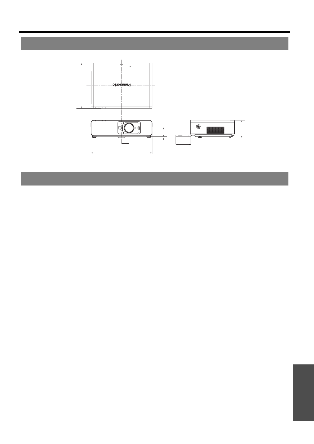
Dimensions
Technical Information
Unit: mm
319 (12 - 17/32")
124.5
(4 - 7/8")
53
(2 - 1/16")
432 (17")
60.5 (2 - 3/8")
85.4
(3 - 11/32")
9.5 (-11/32")
Trademark acknowledgements
VGA and XGA are trademarks of International Business Machines Corporation.
S-VGA is a registered trademark of the Video Electronics Standards Association.
HDMI, the HDMI logo and High-Definition Multimedia Interface are trademarks or registered trademarks of
HDMI Licensing LLC.
The font used in the on-screen displays is a Ricoh bitmap font, which is manufactured and sold by Ricoh
Company, Ltd.
All other trademarks are the property of the various trademark owners.
These Operating Instructions are printed on recycled paper.
ENGLISH - 53
Appendix
Page 54

Index
A
AC IN .........................................................15
Accessories ................................................11
Air exhaust port ............................................15
Air intake port ..............................................14
ALS (Ambient Luminance Sensor) ...................14
ARF (Auto Rolling Filter)
ASPECT .....................................................34
AUDIO BALANCE ........................................38
AUDIO IN ...................................................15
AUTO SETUP
B
BACK COLOUR ...........................................38
Battery compartment .....................................13
BLACKBOARD ............................................38
BRIGHTNESS .............................................32
C
Calculation methods
CD-ROM
Cleaning .....................................................42
CLOCK PHASE ...........................................34
COLOUR ....................................................32
COLOUR TEMPERATURE ............................ 32
COMPONENT IN .........................................15
COMPUTER
COMPUTER AUDIO IN .................................15
COMPUTER SEARCH ..................................13
COMPUTER1 IN ..........................................15
COMPUTER2 IN/1 OUT ................................ 15
COMPUTER2 SELECT .................................36
Connections ................................................20
CONTRAST ................................................32
CONTROL PANEL .......................................37
D
DAYLIGHT VIEW .........................................32
DEFAULT
Appendix
DETAILED SETUP
DIGITAL ZOOM
Dimensions .................................................53
Direct power off ............................................22
Compartment ...........................................15
FILTER indicator .......................................14
FILTER indicator status ...............................41
FILTER REMAINING .................................. 36
Replacing ................................................42
Menu .....................................................37
Remote control .........................................25
Remote control button .................................13
16:9 ......................................................52
4:3 ........................................................16
Accessories .............................................11
Connection guidance .................................. 48
Remote control .........................................26
Remote control button .................................13
Remote control .........................................27
Remote control button .................................13
OPTION menu ..........................................38
PICTURE menu ........................................33
Remote control .........................................28
Remote control button .................................13
DIRECT POWER ON
Function ................................................. 22
Menu ..................................................... 37
DOT CLOCK ............................................... 34
E
ENTER
Control panel button ................................... 14
Remote control button ................................. 13
F
FILTER REMAINING .................................... 36
FILTER SETUP ........................................... 36
Focus lever ........................................... 14, 24
FRAME LOCK ............................................. 35
FREEZE
Remote control ......................................... 27
Remote control button ................................. 13
Front leg adjusters ............................ 15, 17, 24
Front panel cover ......................................... 14
H
Hand strap .................................................. 13
HIGHLAND ................................................. 38
I
INDEX-WINDOW
Remote control ......................................... 27
Remote control button ................................. 13
INITIALISE ALL ........................................... 38
INPUT GUIDE ............................................. 36
INPUT PASSWORD ..................................... 39
INPUT SELECT
Control panel button ................................... 14
Remote control button ................................. 13
Selecting .......................................... 24, 26
INSTALLATION
Menu ..................................................... 37
Projection method ...................................... 17
K
KEYSTONE ................................................ 34
L
LAMP
Indicator ................................................. 14
Indicator status ......................................... 41
LAMP RUNTIME ....................................... 37
Lamp unit compartment ............................... 15
Replacing ............................................... 43
LAN ........................................................... 15
LANGUAGE ................................................ 30
LASER
Remote control ......................................... 26
Remote control button ................................. 13
Lens shift lever ................................ 14, 18, 24
Lever
Focus lever ............................................. 14
Lens shift lever ......................................... 14
Zoom lever .............................................. 14
ENGLISH - 54
Page 55

Index
M
Mains lead
Accessories ............................................. 11
Connecting ............................................. 22
MENU
Control panel button ................................... 14
Main menu .............................................. 30
Navigation .............................................. 29
Remote control button ................................. 13
N
Navigation buttons
Control panel button ................................... 14
Remote control button ................................. 13
NETWORK
Remote control ......................................... 26
Remote control button ................................. 13
NOISE REDUCTION .................................... 33
O
OPTION menu ............................................ 36
OSD DESIGN ............................................. 38
P
PAGE ........................................................ 13
PASSWORD CHANGE ................................. 39
PICTURE menu ........................................... 32
PICTURE MODE ......................................... 32
POSITION .................................................. 34
POSITION menu .......................................... 34
POWER
Control panel ........................................... 14
Indicator ................................................. 14
Indicator status ......................................... 22
Remote control button ................................. 13
POWER OFF TIMER .................................... 37
Projection lens ............................................. 14
R
REMOTE ................................................... 15
LAMP switching ........................................ 49
Pin assignments ....................................... 49
Switching input signals ................................ 49
Remote control
Accessories ............................................. 11
Indicator ................................................. 13
Signal emitter ........................................... 13
Signal receptor ......................................... 14
RESIZING .................................................. 35
RETURN
Control panel button ................................... 14
Remote control button ................................. 13
S
Safety cable
Accessories ............................................. 11
Safeguards ............................................. 44
Screen size
16:9 ...................................................... 52
4:3 ....................................................... 16
Security lock ............................................... 15
SECURITY menu ......................................... 39
SERIAL ......................................................15
Basic format .............................................47
Cable specifications ....................................48
Communication settings ...............................47
Connection ..............................................47
Control commands .....................................48
Pin assignments ........................................47
SHARPNESS ..............................................32
SHUTTER
Remote control ..........................................27
Remote control button .................................13
SIGNAL SEARCH .........................................37
Speaker ......................................................14
Specifications ..............................................50
STARTUP LOGO .........................................36
STILL MODE ...............................................33
Sub-menu ...................................................30
S-VIDEO IN .................................................15
SXGA MODE ...............................................38
T
Technical Information ....................................46
TEMP
Indicator ..................................................14
Indicator status ..........................................41
TEST PATTERN ..........................................38
TEXT CHANGE ............................................39
TEXT DISPLAY ............................................39
Throw distance
16:9 .......................................................52
4:3 ........................................................16
Throwing angle ............................................17
TINT ..........................................................32
Troubleshooting ...........................................45
TV-SYSTEM ................................................33
V
VARIABLE AUDIO OUT .................................15
VIDEO
Remote control ..........................................26
Remote control button .................................13
VIDEO IN ....................................................15
VOLUME ....................................................38
Remote control ..........................................28
Remote control button .................................13
W
WHITE BALANCE ........................................33
X
XGA MODE .................................................38
Z
Zoom lever ............................................14, 24
Appendix
ENGLISH - 55
Page 56

Matsushita Electric Industrial Co., Ltd.
Web Site: http://panasonic.net
© 2007 Matsushita Electric Industrial Co., Ltd. All Rights Reserved.
Printed in Japan
S0207-2067C
 Loading...