

Page 1

I N S T R U C T I O N M A N U A L
Plasma Swivel Stand
PSS-2000BR/SS)
The Plasma Swivel Stand (PSS-2000) is available in black
(PSS-2000BR) or silver (PSS-2000SS) to securely mount
your large flat panel display. A stylish solution for residential,
commercial and business applications, the PSS-200 provides a wide variety of features for most table top installations.
Features include +/-45 degrees of swivel, free standing with
bolt down capability for permanent installation or security,
infinite height adjustment of 5” and two cable options for
ease of installation. The PSS-2000 swivel feature offers
optional stops at +/-15 degrees, 25 degrees or 35 degrees.
The infinite height adjustment of 5” allows for different screen
heights up to 32 inches and cables may extend from the ba ck
of the display or be routed through an access hole in the middle of the stand.
The PSS-2000 uses Chief’s exclusive Q-Latch™ Mounting
System for easy installation, stable mounting and quick
release. A video conferencing shelf, aesthetic cover kit, and
Q-clamps for added security are available.
BEFORE YOU BEGIN
• CAUTION: To prevent damage to the stand, which could affect or void the Factory warranty, thoroughly
study all instructions and illustrations before you begin to install or operate the unit. Pay particular attention to the “Important Precautions” on Page 1.
• The maximum weight to be installed on the PSS is 150 pounds (68.36 Kg)
• If you have any questions about this assembly, contact Chief Manufacturing at 1-800-582-6480 or 952-582-6480.
CHIEF MANUFACTURING INC.
1-800-582-6480 952-894-6280 FAX 952-894-6918
8401 EAGLE CREEK PARKWAY, STE. 700
SAVAGE, MINNESOTA 55378 USA
PART NO. 8800-000039 (Rev. D)
©2004 Chief Manufacturing
www.chiefmfg.com
09-05
Page 2

Instruction Manual Swivel Stand
IMPORTANT WARNINGS and CAUTIONS!
WARNING: A WARNING alerts you to the possibility of serious injury or death if you do not follow the instructions.
CAUTION: A CAUTION alerts you to the possibility of damage or destruction of equipment if you do not follow the corre-
sponding instructions.
• WARNING:Improper installation can result in serious personal injury! Make sure that the structural members can
support a redundant weight factor five times the total weight of the equipment: if not, reinforce the structure before installing the table stand.
• WARNING:Be aware also of the potential for personal injury or damage to the unit if it is not adequately mounted.
• CAUTION: Inspect the unit for shipping damage.
• CAUTION: Do not use cleanser or harsh cleaning agents on displays.
TOOLS REQUIRED FOR INSTALLATION
• Phillips screwdriver
NOTE: Other tools may be required depending on the
method of installation.
CONTENTS
INSPECT PARTS BEFORE ASSEMBLY ......... 2
DISPLAY PREPARATION PROCEDURES ..... 3
STAND ASSEMBLY PROCEDURES ............... 3
DISPLAY INSTALLATION PROCEDURES ... 5
STAND ADJUSTMENT PROCEDURES .......... 5
STAND ANCHORING PROCEDURES ............ 6
CABLE MANAGEMENT .................................. 6
1
Page 3
Instruction Manual Swivel Stand
INSPECT PARTS BEFORE ASSEMBLY
Remove and Inspect the Stand
1. Open shipping container , remove unit from cont ainer , and
remove wooden shipping base.
2. Carefully inspect the stand for shipping damage. If any
damage is apparent, call your carrier claims agent and do
not continue with the assembly procedure until the carrier
has reviewed the damage.
NOTE:
Read all assembly instructions before start-
ing assembly.
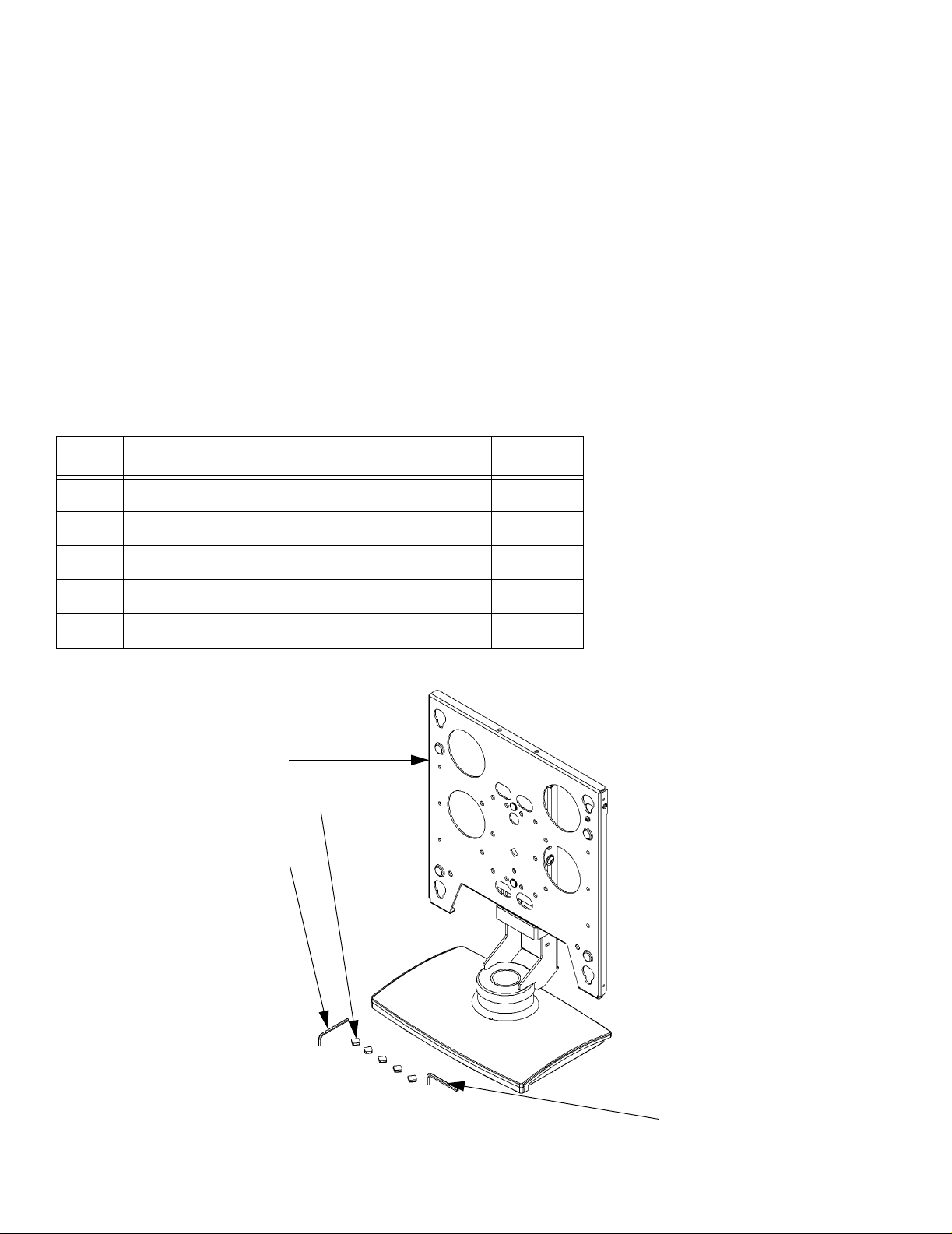
3. Carefully inspect all components for damage (See
able 1 and Figure 1).
Table 1:
Item # Description Quantity
10 Stand Assembly 1
20 Bumper, rubber 5
30 Wrench, Allen, 3/16” 1
40 Wrench, Allen, 5/32” 1
50 Template, paper (Not Shown) 1
10
20
30
40
Figure 1. Parts
2
Page 4

Instruction Manual Swivel Stand
DISPLAY PREPARATION PROCEDURES
Prepare the display for installation as follows:
1. Install the PSB bracket (shipped with the PSS) on your
display according to the instructions included in PSB
bracket package.
STAND ASSEMBLY PROCEDURES
Free Standing (not anchored) Applications Only:
NOTE: Do not perform this step if you are going to anchor
the stand to a surface.
1. Install five rubber bumpers on the bottom of the stand
(see Figure 1).
Display Measuring 30 Inches or Smaller In Height:
NOTE: Stand comes assembled for displays 30” in height or
less and lowered to its minimum height for shipment.
1. Loosen the four height adjustment screws and raise the
slide to its maximum height (see Figure 2).
2. Secure the slide in place by tightening the four height
adjustment screws.
Display Measuring More Than 30 Inches In Height:
1. Remove the slide from the base by removing four height
adjustment screws (see Figure 3).
2. Remove the front plate from the slide by removing two
nuts securing the front plate (see Figure 3).
Attach rubber bumpers here
Figure 1. Free Standing Installations Only
Adjust height using these screws
3. Install the front plate in the upper mounting holes of slide
and secure using the two nuts removed in the previous
step (see Figure 4).
4. Install the slide on the base using the four height adjust-
ment screws (see Figure 3).
5. Raise the slide to its maximum height (see Figure 2).
6. Secure the slide in place by tightening the four height
adjustment screws.
Figure 2. Height Adjustment
3
Page 5

Instruction Manual Swivel Stand
Height Adj.
Screws
Slide
Front Plate
Nuts
Figure 3. Stand Assembly
Flag in down
(lowered)
Nuts
Holes used for displays measuring
less than 30 Inches Tall
Reattach front plate using these holes
position
Figure 4. For displays Taller Than 30 Inches
4
Page 6

Instruction Manual Swivel Stand
DISPLAY INSTALLATION PROCEDURES
Install the display as follows:
1. Make sure the latching flag of the stand is in the open
(lowered) position (see Figure 4).
2. Align the mounting buttons of the PSB bracket, installed
on your display, with the teardrop slots in the mounting
plate of the stand.
3. Lower the display into place and raise the latching flag to
secure the display. If the latching flag will not engage
completely, the display is not properly mounted. Make
sure the mounting buttons rest at the bottom of the teardrop slots.
STAND ADJUSTMENT PROCEDURES
Adjust display height as follows:
CAUTION: Displays are fragile. Allowing the display to drop to
the bottom of stand travel may result in damage to the display.
1. While holding the display in place, loosen the four height
adjustment screws (see Figure 2).
2. Position the display to the desired height.
3. Tighten the four height adjustment screws (see Figure 2).
Adjust stand tension as follows:
1. With the display secured to the stand assembly, check
swivel tension.
Adjust swivel tension using these screws
Figure 5. Tension Adjustment Screws
Select swivel stop by inserting
10-24 X 1/2” Phillips head screw
in one of these holes
2. If tension adjustment is necessary, slightly tighten or
loosen adjustment screws on stand assembly (see Figure 5).
3. Repeat Step 1 and Step 2 as necessary.
Adjust stand swivel stop as follows:
1. If desired, insert the 10-24 X 1/2” Phillips head cap screw
in one of the three swivel stop holes (15, 25 or 35
degrees) in the base of the stand (see Figure 6).
Figure 6. Swivel Stops (15, 25 or 35 Degrees)
5
Page 7

Instruction Manual Swivel Stand
STAND ANCHORING PROCEDURES
NOTE: Due to the wide variety of anchoring options, hard-
ware is not provided.
Anchor stand follows:
1. Select a suitable location for anchoring, allowing for room
for swivel and access for cabling.
2. Using the template provided, drill anchoring holes for the
four 1/4-20 X 1/2” tapped holes (see Figure 7).
3. If routing cables through mounting surface, Use the template provided and drill the cable access hole in the
mounting surface.
CABLE MANAGEMENT
Install cables as follows:
1. Attach cabling to flat panel display.
2. Route cables in one of three ways:
a. down the back of the display (open),
1/4-20 X 1/2” Tapped holes
Figure 7. Anchoring Hole Locations
b. through the center post of the stand and out the bot-
tom of the stand in the back,
c. through the center post of the stand and through a
hole in the mounting surface.
6
 Loading...