

Page 1
EN
Starter’s Guide
ES
Manual de inicio
FR
Guide de démarrage
RFX9400
Page 2

Page 3
RFX9400 Starter’s Guide
RFX9400
Starter’s Guide
Manual de inicio
Guide de démarrage
ENGLISH
ESPAÑOLFRANÇAIS
Page 4
RFX9400 Starter’s Guide
RFX9400 Starter’s Guide
Contents
Before You Start..............................................2
Unpacking the Extender
Configuring the Extender
Stand-alone Connection
Network Connection
Installing the Extender
Connecting the Extender to AV-equipment
Stand-alone Mode
...................................3
..................................4
...............................4
....................................4
.....................................6
.........6
Support..........................................................7
Troubleshooting
Firmware Update
Specifications
IFU Approbation / Safety Content RFX9400
FCC Compliancy
Regulations According to R&TTE
..........................................7
........................................9
...............................................10
...........i
..........................................i
.....................ii
Network Mode
1
Page 5
RFX9400 Starter’s GuideRFX9400 Starter’s Guide
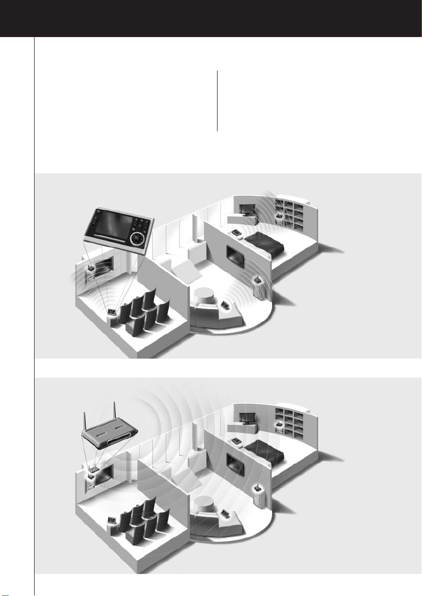
Before You Start
The Pronto Wireless Extender is an important element of the Pronto System and makes it possible
to control AV-equipment via RF in the entire house.
In order to use the Extender in a wireless Pronto Network:
• Configure the Extender: connect it to the PC and use the Configuration Tool.
• Install the Extender: connect it to external AV-equipment, like a TV or receiver.
The Extender can be used in two ways:
Stand-alone Mode
This is the so-called ‘Ad-Hoc Mode’: a router is not required.
Stand-alone Advantages:
• The Extender is easily configured and installed.
• It operates independently from other networks and network settings.
Refer to the chapter ‘Stand-alone Connection’ on page 4 to configure the Extender in Stand-alone
Mode.
Note If you want to use the Escient Fireball audio server in combination with one or more Extenders,
the Extenders have to be configured in Network Mode.
ENGLISH
Network Mode
This is the so-called ‘Infrastructure Mode’: the Extender is used in a network with a router.
Network Advantages:
•A network allows the use of repeaters, which enlarges the range of the Pronto System.
• When using a dedicated Pronto Network, the Extender can operate independently from settings
in other networks.
• The Extender in Network Mode can be given a fixed IP address, which increases reliability.
• The network connection can be encrypted.
Refer to the chapter ‘Network Connection’ on page 4 to configure the Extender in Network Mode.
Note An Extender that has been configured in Stand-alone Mode can always be reconfigured for use
in Network Mode and vice versa.
You can use up to 16 different Extenders in the same Pronto Network.
2
Page 6
RFX9400 Starter’s Guide
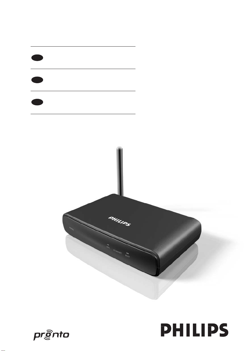
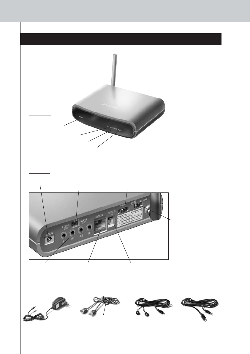
Unpacking the Extender
Pronto Wireless Extender
Front Panel
Power LED
WiFi LED
Ethernet LED
Busy LED
Back Panel
Power input
4 dipswitches for
the IR outputs
Antenna
Stand-alone/
Network switch
Configuration switch
• In Stand-alone Mode:
changes the RF
channel.
• In Network Mode:
indicates the
connection type.
4 IR outputs
(RJ45)
Power Adapter Configuration Cable
Crossed Ethernet cable
Extender ID switchEthernet input
2 Dual IR Emitters
2 Mini-jack IR Cables
3
Page 7

Configuring the Extender
RFX9400 Starter’s Guide
Note Before you start configuring the Extender, check if there are any firmware updates available in
the Downloads section on www.pronto.philips.com.
Refer to the chapter ‘Firmware Update’ on page 9 for further details.
Stand-alone Connection
To configure the Stand-alone Extender:
1 Plug in the Extender’s power adapter.
The Extender will start up. When start-up has finished, the Power and WiFi LEDs are green.
2 Use the default switch settings of the Extender:
Stand-alone/Network Stand-alone
Configuration switch 1
Extender ID 0
Note • If there is already an Extender with ID 0, set the Extender ID switch to an ID that is not
used yet.
• If there is any interference with other products in or around the house, the
Configuration switch can be set to a different RF channel.
•Make sure the same Extender ID and RF channel are used on the Extender and the
Pronto Control Panel.
3 Configure the Control Panel’s configuration file so that the Control Panel can work
with the Extender. For more details, refer to the ProntoEdit Professional Online Help.
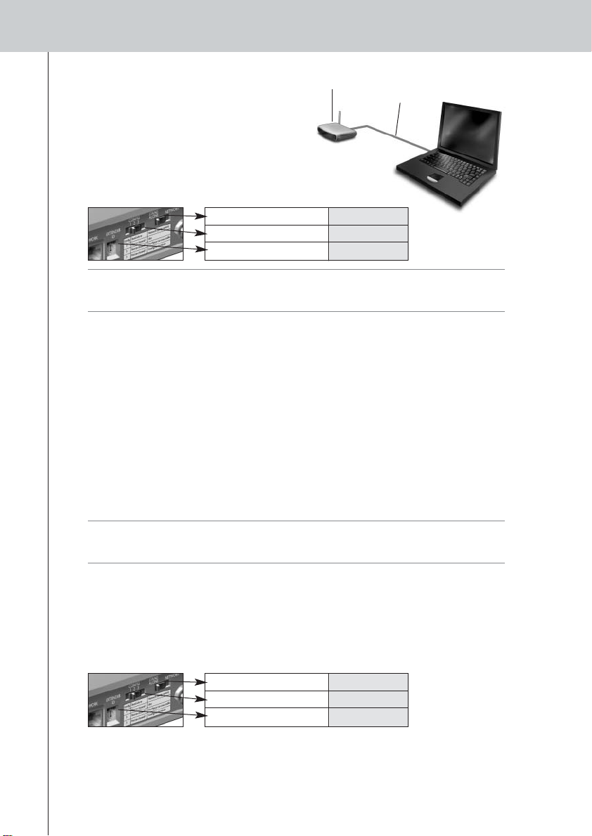
Network Connection
In the case of a network connection, the Extender is made part of the wireless Pronto Network.
There are two ways to use the Extender in a network:
• Wired connection
Straight Ethernet Cable
ENGLISH
• Wireless connection
Extender
Extender
Router
Wireless
Access Point
Control Panel
Wireless
Access Point
Control Panel
4
Page 8
RFX9400 Starter’s Guide
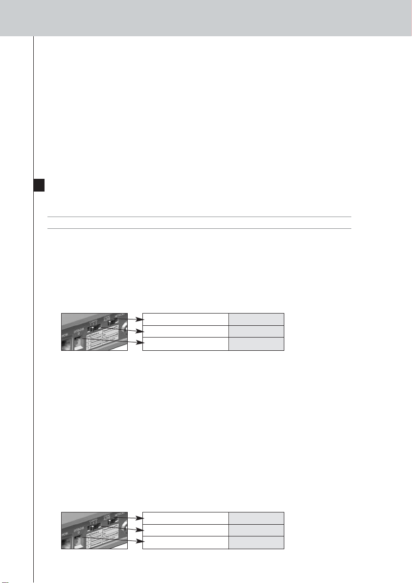
To configure the Network Extender:
Extender Configuration
cable
1 Connect the Extender to the PC with the
configuration cable (this is the crossed
Ethernet cable enclosed).
2 Set the switches correctly:
Stand-alone/Network Network
Configuration switch 2
Extender ID 0
Note • If there is already an Extender with ID 0, set the Extender ID switch to an ID that is not
used yet.
•Make sure the same Extender ID is used on the Extender and the Pronto Control Panel.
3 Plug in the Extender’s power adapter.
The Extender will start up. After startup, the Power and Ethernet LEDs are green and the Busy
LED is red/green blinking.
4 Open the browser.
5 Type the IP address of the Extender (printed on the bottom of the Extender) in the
address bar of the browser.
The Configuration Tool opens in the browser.
6 Follow the onscreen instructions and make sure you have the following information at
hand:
• If the Extender will be connected wirelessly to the Pronto Network: the SSID and
encryption settings.
• If the Extender will be operating with a fixed IP address: the IP address, netmask and
default gateway.
Tip To ensure optimal performance, use a dedicated network for all Pronto communication.
This makes the Pronto Network independent from other network traffic and changes in
network settings.
7 Disconnect the Extender from the PC.
8 Connect the Extender to the Pronto Network:
• For a wired connection, connect the Extender to the router by means of a straight Ethernet
cable.
• For a wireless connection, you do not need to connect any more cables.
9 Set the switches correctly:
Stand-alone/Network Network
Configuration switch 1
Extender ID 0
The Extender will restart. After startup,
• In a wired network connection, the Power and Ethernet LEDs are green and the Busy LED
blinks green when it’s processing a code or a macro from the Control Panel.
• In a wireless network connection, the Power and WiFi LEDs are green and the Busy LED
5
blinks green when it’s processing a code or a macro from the Control Panel.
Page 9
RFX9400 Starter’s Guide
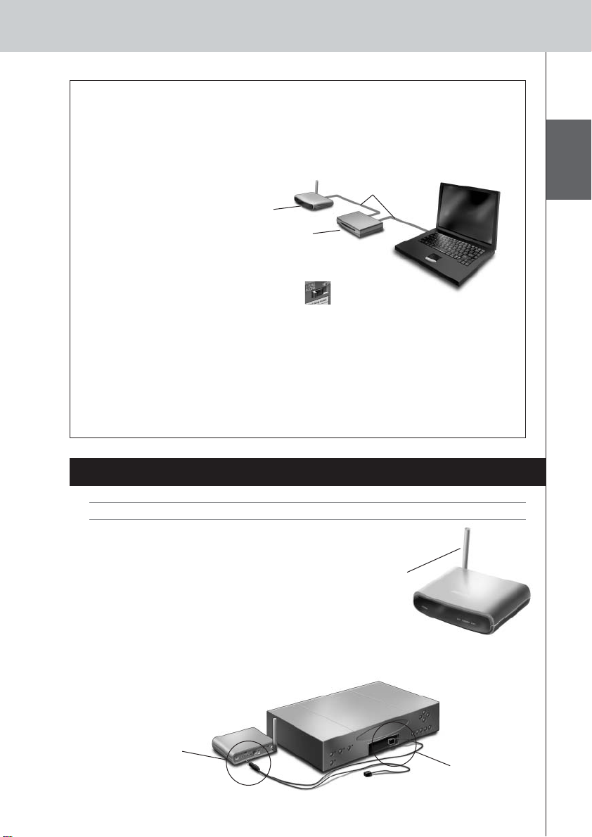
Configuring the Extender through a Router
When the Extender is already installed and connected to external AV-equipment, it is possible to
configure it through a router.
1 Connect the Extender to the router, and the router to the PC, as indicated below.
Straight
Ethernet cable
Extender
Router
2 Set the Extender’s Configuration switch to 3.
3 Open the ProntoEdit Professional on the PC.
4 In the Tools menu, select Extender Discovery.
The Extender Discovery tool appears, with a list of all the detected Extenders in the Pronto
Network.
5 Select the Extender that you want to configure and click on the Configure button.
The Configuration Tool opens in the browser.
6 Finalize the configuration, as described in the instructions on page 5.
ENGLISH
Installing the Extender
Warning Keep the Extender away from heat sources such as amplifiers.
Before connecting the Extender to external AV-equipment,
make sure that the antenna is placed correctly.
Place the antenna
in an upright
position.
Connecting the Extender to AV-equipment
To connect the Extender to AV-equipment, use one of the following cables enclosed with the
Extender:
•a Dual IR emitter;
Insert the mini-jack
connector of the
Dual IR emitter in
the IR output of
the Extender.
Attach the
emitter to the
infrared receiver
of the AVcomponent.
6
Page 10
RFX9400 Starter’s Guide
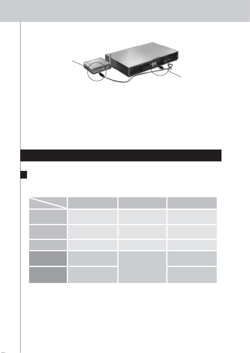
-or-
•a mini-jack IR cable.
Insert one mini-jack
connector of the
mini-jack cable in
the IR output of the
Extender.
Insert the other
mini-jack
connector in the
AV-component.
Adjusting the Power Level of the IR Outputs
At the back of the Extender, there are 4 dipswitches, one for each IR output. Use these dipswitches
to configure the power level of the Dual IR emitters and the mini-jack cables.
For example, flip the dipswitch down to lower the power level when the Extender is connected to
an external IR bus system.
Support
Troubleshooting
What Do the LEDs Indicate?
LEDs
Colors
Green blinking
Green
Red/green blinking
Red
Red blinking
There is an IP conflict
There is another AV-component in the network that is using the same fixed IP address as the
Extender. Change the IP address of the Extender in the Configuration Tool.
If the problem persists, check the router settings.
The IP address cannot be determined
• When using the Extender: make sure that the Extender is connected to the router with a straight
7
Ethernet cable.
Ethernet LED WiFi LED Busy LED
The Extender’s IP address is
being determined.
The Extender is functioning
normally.
–
Refer to the topic ‘There is an
IP conflict’ on page 7.
Refer to the topic ‘The IP address
cannot be determined’ on
page 7.
The Extender’s IP address is
being determined.
The Extender is functioning
normally.
– The Extender is being
Refer to the topic
‘The Extender cannot
communicate with the
wireless network’ on page 8.
The Extender is busy processing
a short code or macro from the
Control Panel.
The Extender is busy processing
a long macro from the Control
Panel.
configured.
Refer to the topic ‘There are
duplicate Extender IDs’
on page 8.
The Extender is starting up.
Wait until startup has finished.
Page 11

RFX9400 Starter’s Guide
• When configuring the Extender: make sure the PC is not using a fixed IP address but is using
DHCP instead.
•Make sure the router is switched on. If the router is using DHCP, the Extender’s IP address cannot
be determined. Make sure to use the correct network settings on the router.
The Extender cannot communicate with the wireless network
The WiFi LED is red
•Make sure that the Extender is in range of the Wireless Access Point.
•Make sure that you filled in the correct secret in the Configuration Tool.
• Add the Extender’s MAC address to the router’s list of accepted MAC addresses.
The WiFi LED is red blinking
• Check the router’s network settings and make sure that it can operate with the Extender.
• If the LED doesn’t stop blinking, unplug the power adapter, wait a few seconds, and plug it in
again.
Finding the Exact Location of an AV-component’s IR Receiver
1 Remove the protective tape of the Dual IR emitters.
2 Set the Dual IR emitters to the minimal power level, and hold the adhesive side of one
of the emitters 0.4 - 0.8 inch / 1 - 2 cm in front of the AV-component.
3 Make sure the Control Panel is configured to operate with the AV-component.
4 Move the emitter across the front panel of the AV-component, and at the same time,
send commands with the Control Panel to the AV-component.
Take note of when the AV-component reacts to the IR signals of the emitter.
5 When the AV-component reacts, position the emitter in that place.
ENGLISH
Operating AV-components with the Extender
The AV-components do not respond to commands from the Extender
• Check if the Busy LED blinks green when you send a command with the Control Panel. If the Busy
LED does not blink, the Extender is not receiving commands from the Control Panel;
•Make sure that the Control Panel is configured correctly in ProntoEdit Professional;
•Make sure that the Extender is configured correctly in the Configuration Tool and connected
properly to the AV-components;
•Make sure that the switches on the Extender are set correctly.
•Make sure that the Wireless Access Point is on and configured correctly.
•Make sure that the Extender is in range of the Wireless Access Point. If the Wireless Access
Point is placed higher or lower than the Extender, place the Extender’s antenna horizontally for
optimum range.
There are duplicate Extender IDs
Using the Extender ID switch, assign a unique ID to each Extender in the same Pronto Network.
Make sure the Control Panel is configured accordingly in ProntoEdit Professional.
You can use up to 16 different Extenders in the same Pronto Network.
8
Page 12
RFX9400 Starter’s Guide
The Busy LED blinks green when the Control Panel is not in use
This does not mean that something is wrong with the Extender. It merely indicates that the Extender
is being operated by a different Control Panel. When the Busy LED stops blinking, you can use the
Extender again.
Resetting the Extender
This is only necessary when the Extender displays unusual behavior.
To perform a reset, unplug the Extender from the electrical socket. Wait a few seconds, and plug it
in again.
Firmware Update
When an update of the Extender firmware is available, this will be announced on the Philips Pronto
website: www.pronto.philips.com.
Note You can always see the current version of the firmware in the Configuration Tool.
1 Download the new version of the firmware on the PC.
2 Unplug the Extender. The Extender can be updated in the following ways.
Updating the Extender with the configuration cable
Connect the Extender to the PC with the configuration cable.
1
2 Set the switches correctly.
Stand-alone/Network Network
Configuration switch 2
Extender ID 0
3 Open the browser.
4 Type the IP address of the Extender (printed on the bottom of the Extender) in the
address bar of the browser.
The Configuration Tool opens in the browser.
5 Select Firmware Update in the left navigation pane.
The Firmware Update page opens.
6 Follow the onscreen instructions.
Updating the Extender through a router
If the Extender is already installed and connected to AV-equipment, it may be more convenient to
update it through a router.
1 Connect the Extender to the router, and the router to the PC.
2 Set the switches correctly.
Stand-alone/Network Network
Configuration switch 3
Extender ID 0
9
Page 13

RFX9400 Starter’s Guide
3 Open the ProntoEdit Professional on the PC.
4 In the Tools menu, select Extender Discovery.
The Extender Discovery tool appears, with a list of all the detected Extenders in the Pronto
Network.
5 Select the Extender that you want to configure and click on the Configure button.
The Configuration Tool opens in the browser.
6 Select Firmware Update in the left navigation pane.
The Firmware Update page opens.
7 Follow the onscreen instructions.
Specifications
The specifications and design of this product are subject to change without notice.
ENGLISH
General Dark grey ABS housing with poly carbonate front plate
Modes Stand-alone (wireless): Similar to WiFi ad-hoc mode; no access point and
Dimensions 3,98 x 6,18 x 1,3 inch (101,2 x 157 x 33,5 mm)
Operating temperature 32°F to 122°F (0°C to 50°C)
Infrared (IR) IR frequency range: 25kHz-1MHz (including DC/flash codes)
Radio Frequency (RF) 802.11g at 2.4 GHz with additional proprietary protocol
Dual IR emitters Number of IR emitters: up to 4 (2x2), emitters wired in series
Mono mini-jack cables 0.13 inch (3.5 mm) mono mini-jack
Power adapter 100V-240 VAC / 50-60 Hz Power adapter (5V DC/2A output, UL-CE approved)
802.11 b/g compliant RF technology
4 LED indications for Power, WiFi, Network and Busy
Up to 16 extenders and 16 control panels in a system (for all modes)
4 addressable outputs for IR emitters
Ethernet RJ45 connection
Rotatable RF antenna
Positioning: freestanding or mounted in any position
router required
Network (wireless): Similar to WiFi infrastructure mode; used in a system with
a router and access point
Network (wired via Ethernet): used in a system with a router and access point
IR power out: 2 levels
0.13 inch (3.5 mm) mono mini-jack
Cable length: 9 ft (2.7 meters)
Cable length: 5 ft (1.5 meters)
Pronto Wireless Extender Starter’s Guide
© Copyright 2006 Royal Philips Electronics, Interleuvenlaan 72 - 74, 3000 Leuven (Belgium)
Remarks:
All rights are reserved. Reproduction in whole or in part is prohibited without prior consent of the copyright owner.
Royal Philips Electronics is not liable for omissions or for technical or editorial errors in this manual or for damages
directly or indirectly resulting from the use of the Pronto Wireless Extender.
The information in this Starter’s Guide may be subject to change without prior notice.
All brand or product names are trademarks or registered trademarks of their respective companies or organizations.
10
Page 14

RFX9400 Manual de inicio
RFX9400 Manual de inicio
Contenido
Antes de empezar ...........................................2
Contenido del paquete del Extensor
Configuración del Extensor
Conexión Stand-alone
Conexión Network
Instalación del Extensor
......................................4
...................................6
Conexión del Extensor a un equipo AV
Modo Stand-alone
(modo autónomo)
...................3
...............................4
..................................4
.............6
Asistencia ......................................................7
Detección de errores
Actualización de Firmware
Especificaciones
IFU Approbation / Safety Content RFX9400
FCC Compliancy
Regulations According to R&TTE
...................................7
............................9
...........................................10
...........i
..........................................i
.....................ii
Modo Network
(modo red)
1
Page 15

RFX9400 Manual de inicio
Antes de empezar
El Pronto Wireless Extender es un elemento importante del Sistema Pronto y permite controlar
equipos AV mediante RF en toda la casa.
Para utilizar el Extensor en una red Pronto inalámbrica:
• Configure el Extensor: conéctelo al PC y utilice la herramienta de configuración Configuration
Tool.
• Instale el Extensor: conéctelo a un equipo AV externo, como un televisor o un receptor.
El Extensor puede utilizarse en dos modalidades:
Modo Stand-alone (modo autónomo)
Esta modalidad también se conoce como “modo Ad-Hoc”: no se requiere router.
Ventajas del modo Stand-alone:
• El Extensor se instala y se configura fácilmente.
• Funciona independientemente de otras redes o configuraciones de red.
Consulte el capítulo ‘Conexión Stand-alone’ en la página 4 para configurar el Extensor en modo
Stand-alone.
Nota Si desea utilizar el servidor de audio Escient Fireball en combinación con uno o más Extensores,
los Extensores deben estar configurados en modo Network.
Modo Network (modo red)
Esta modalidad también se conoce como “modo Infraestructura”: el Extensor se utiliza en una red
con un router.
Ventajas del modo Network:
• Una red permite el uso de repetidores, lo que aumenta el radio de alcance del Sistema Pronto.
• Cuando se utiliza una red Pronto dedicada, el Extensor puede funcionar independientemente de
las configuraciones de otras redes.
• Se puede asignar una dirección IP fija al Extensor en modo Network, lo que aumenta la fiabilidad.
• La conexión de red se puede cifrar.
ESPAÑOL
Consulte el capítulo ‘Conexión Network’ en la página 4 para configurar el Extensor en modo Network.
Nota Un Extensor configurado en modo Stand-alone puede reconfigurarse para uso en modo
Network, y viceversa.
Puede utilizar hasta 16 Extensores diferentes en la misma red Pronto.
2
Page 16

RFX9400 Manual de inicio
Contenido del paquete del Extensor
Pronto Wireless Extender
Antena
Panel frontal
Indicador
LED Power
(encendido)
Indicador LED WiFi
Indicador LED Ethernet
Indicador LED Busy (ocupado)
Panel trasero
Entrada de
corriente
4 conmutadores DIP
para las salidas IR
Interruptor
Stand-alone/ Network
Interruptor de
Configuración
• En modo Stand-alone:
cambia el canal RF.
• En modo Network:
indica el tipo de
conexión.
4 salidas IR
Adaptador de
corriente
Entrada Ethernet
(RJ45)
Cable de configuración
Cable Ethernet cruzado
Interruptor del ID
del Extensor
2 emisores IR duales
2 cables IR con
conectores mini-jack
3
Page 17

Configuración del Extensor
RFX9400 Manual de inicio
Nota Antes de empezar a configurar el Extensor, compruebe si hay alguna actualización de firmware
disponible en la sección de Downloads de www.pronto.philips.com.
Consulte el capítulo ‘Actualización de Firmware’ en la página 9 para obtener más información
al respecto.
Conexión Stand-alone
Para configurar el Extensor Stand-alone:
1 Conecte el adaptador de corriente del Extensor.
El Extensor arrancará. Cuando finalice el proceso de arranque, los indicadores LED Power y
WiFi estarán iluminados en verde.
2 Utilice la configuración de los interruptores por omisión del Extensor:
Stand-alone/Network Stand-alone
Interruptor de Configuración 1
ID del Extensor 0
Nota • Si ya existe un Extensor con el ID 0, ajuste el interruptor del ID del Extensor a un ID que
no esté en uso.
• Si hay alguna interferencia con otros productos dentro o cerca de la casa, se puede
ajustar el interruptor de Configuración a un canal RF distinto.
• Asegúrese de que utiliza el mismo ID del Extensor y canal RF en el Extensor y en el
Control Panel de Pronto.
3 Configure el archivo de configuración del Control Panel (el Panel de Control) para que
el Control Panel pueda trabajar con el Extensor. Para más información, consulte la
ayuda ProntoEdit Professional Online Help.
Conexión Network
En el caso de una conexión de red, el Extensor forma parte de la red Pronto inalámbrica. Hay dos
maneras de utilizar el Extensor en una red:
• Conexión con cable
Cable Ethernet directo
ESPAÑOL
• Conexión inalámbrica
Extensor
Extensor
Router
Punto de
acceso inalámbrico
Punto de
acceso inalámbrico
Control Panel
Control Panel
4
Page 18

RFX9400 Manual de inicio
Para configurar el Extensor Network:
1 Conecte el Extensor al PC con el cable de
configuración (el cable Ethernet cruzado
incluido).
2 Ajuste los interruptores correctamente:
Stand-alone/Network Network
Interruptor de Configuración 2
ID del Extensor 0
Extensor
Cable de configuración
Nota • Si ya existe un Extensor con el ID 0, ajuste el interruptor del ID del Extensor a un ID que
no esté en uso.
• Asegúrese de que utiliza el mismo ID del Extensor en el Extensor y en el Control Panel
de Pronto.
3 Conecte el adaptador de corriente del Extensor.
El Extensor arrancará. Después de arrancar, los indicadores LED Power y Ethernet estarán
iluminados en verde, y el indicador LED Busy parpadeará en rojo/verde.
4 Abra el navegador.
5 Escriba la dirección IP del Extensor (impresa en la parte inferior del Extensor) en la
barra de direcciones del navegador.
La herramienta Configuration Tool se abrirá en el navegador.
6 Siga las instrucciones que aparecen en pantalla y asegúrese de que tiene la siguiente
información a mano:
• Si el Extensor va a conectarse de forma inalámbrica a la red Pronto: la configuración de
cifrado y SSID.
• Si el Extensor va a funcionar con una dirección IP fija: la dirección IP, la máscara de red
y la puerta de enlace predeterminada.
Consejo Para garantizar un rendimiento óptimo, utilice una red dedicada para todas las
comunicaciones Pronto. De este modo, la red Pronto se hace independiente de otros
tráficos de red y de cambios en las configuraciones de red.
7 Desconecte el Extensor del PC.
8 Conecte el Extensor a la red Pronto:
• Para una conexión por cable, conecte el Extensor al router utilizando un cable Ethernet directo.
• Para una conexión inalámbrica, no necesita conectar ningún otro cable.
9 Ajuste los interruptores correctamente:
Stand-alone/Network Network
Interruptor de Configuración 1
ID del Extensor 0
El Extensor se reiniciará. Cuando haya arrancado,
• En una conexión de red por cable, los indicadores LED Power y Ethernet estarán iluminados
en verde, y el indicador LED Busy parpadeará en verde cuando se procese un código o una
macro desde el Control Panel.
• En una conexión de red inalámbrica, los indicadores LED Power y WiFi estarán iluminados
en verde, y el indicador LED Busy parpadeará en verde cuando se procese un código o una
5
macro desde el Control Panel.
Page 19

RFX9400 Manual de inicio
Configuración del Extensor a través de un router
Cuando el Extensor está instalado y conectado a un equipo AV externo, es posible configurarlo a
través de un router.
1 Conecte el Extensor al router, y el router al PC, tal como se indica a continuación.
Cable Ethernet directo
Extensor
Router
2 Ajuste el interruptor de Configuración del Extensor a la posición 3.
3 Abra ProntoEdit Professional en el PC.
4 En el menú Tools, seleccione Extender Discovery.
La herramienta Extender Discovery aparecerá, con una lista de todos los Extensores detectados
en la red Pronto.
5 Seleccione el Extensor que quiera configurar y pulse el botón Configure.
La herramienta Configuration Tool se abrirá en el navegador.
6 Finalice la configuración, tal como se describe en las instrucciones de la página 5.
ESPAÑOL
Instalación del Extensor
Advertencia Mantenga el Extensor lejos de fuentes de calor como, por ejemplo, amplificadores.
Antes de conectar el Extensor a un equipo AV externo,
asegúrese de que ha colocado la antena correctamente.
Conexión del Extensor a un equipo AV
Para conectar el Extensor a un equipo AV, utilice uno de los siguientes cables incluidos con el
Extensor:
• un emisor IR dual;
Introduzca el
conector mini-jack
del emisor IR dual
en la salida IR del
Extensor.
Coloque la
antena en
posición vertical.
Conecte el
emisor al
receptor de
infrarrojos del
componente AV.
6
Page 20

RFX9400 Manual de inicio
-o-
• un cable IR con conectores mini-jack.
Introduzca un
conector del cable
con conectores
mini-jack en la
salida IR del
Extensor.
Introduzca el
otro conector en
el componente
AV.
Ajuste del nivel de corriente de las salidas IR
En la parte trasera del Extensor, hay 4 conmutadores DIP, uno para cada salida IR. Utilice estos
conmutadores DIP para configurar el nivel de corriente de los emisores IR duales y los cables con
conectores mini-jack.
Por ejemplo, gire el conmutador DIP hacia abajo para bajar el nivel de corriente cuando el Extensor
esté conectado a un sistema bus IR externo.
Asistencia
Detección de errores
¿Qué indican los indicadores LED?
Colores
Parpadeo verde
Verde
Parpadeo rojo/verde
Rojo
Parpadeo rojo
Ind. LED
Hay un conflicto de IP
Hay otro componente AV en la red que está utilizando la misma dirección IP fija que el Extensor.
Cambie la dirección IP del Extensor en la herramienta Configuration Tool.
Si el problema persiste, compruebe la configuración del router.
La dirección IP no puede determinarse
• Al utilizar el Extensor: asegúrese de que el Extensor esté conectado al router con un cable
7
Ethernet directo.
Indicador LED Ethernet Indicador LED WiFi Indicador LED Busy
Se está determinando la
dirección IP del Extensor.
El Extensor está funcionando con
normalidad.
–
Consulte el tema ‘Hay un
conflicto de IP’ en la página 7.
Consulte el tema ‘La dirección IP
no puede determinarse’ en la
página 7.
Se está determinando la
dirección IP del Extensor
El Extensor está funcionando
con normalidad
– Se está configurando el Extensor.
Consulte el tema ‘El Extensor
no puede establecer
comunicación con la red
inalámbrica’ en la página 8.
El Extensor está ocupado
procesando una macro o un código
corto desde el Control Panel.
El Extensor está ocupado
procesando una macro larga desde
el Control Panel.
Consulte el tema ‘Hay ID del
Extensor duplicados’ en la página 8.
El Extensor está arrancando. Espere
hasta que termine de arrancar.
Page 21

RFX9400 Manual de inicio
• Al configurar el Extensor: asegúrese de que el PC no esté utilizando una dirección IP fija, sino
DHCP.
• Asegúrese de que el router esté encendido. Si el router utiliza DHCP, la dirección IP del Extensor
no podrá determinarse. Asegúrese de que utiliza la configuración de red correcta en el router.
El Extensor no puede establecer comunicación con la red inalámbrica
El indicador LED WiFi está iluminado en rojo
• Asegúrese de que el Extensor está dentro del radio de alcance del punto de acceso inalámbrico.
• Asegúrese de haber introducido el secreto correcto en la herramienta Configuration Tool.
• Añada la dirección MAC del Extensor a la lista de direcciones MAC aceptadas del router.
El indicador LED WiFi parpadea en rojo
• Compruebe la configuración de red del router y asegúrese de que puede funcionar con el Extensor.
• Si el indicador LED no deja de parpadear, desenchufe el adaptador de corriente, espere unos
segundos y vuelva a enchufarlo.
Cómo encontrar la ubicación exacta del receptor IR de un
componente AV
1 Retire la cinta protectora de los emisores IR duales.
2 Ajuste los emisores IR duales al nivel de corriente mínimo y mantenga la banda
adhesiva de uno de los emisores 1 o 2 cm delante del componente AV.
3 Asegúrese de que el Control Panel está configurado para funcionar con el
componente AV.
4 Mueva el emisor por el panel frontal del componente AV y, al mismo tiempo, envíe
instrucciones con el Control Panel al componente AV.
Tome nota de cuándo el componente AV reacciona a las señales IR del emisor.
5 Cuando el componente AV reaccione, sitúe el emisor en ese lugar.
ESPAÑOL
Funcionamiento de los componentes AV con el Extensor
Los componentes AV no responden a las instrucciones del Extensor
• Compruebe si el indicador LED Busy parpadea en verde cuando envía una instrucción con el
Control Panel. Si el indicador LED Busy no parpadea, el Extensor no está recibiendo instrucciones
del Control Panel.
• Asegúrese de que el Control Panel está configurado correctamente en ProntoEdit Professional.
• Asegúrese de que el Extensor está configurado correctamente en la herramienta Configuration
Tool y que está conectado correctamente a los componentes AV.
• Asegúrese de que los interruptores del Extensor están ajustados correctamente.
• Asegúrese de que el punto de acceso inalámbrico está activo y configurado correctamente.
• Asegúrese de que el Extensor está dentro del radio de alcance del punto de acceso inalámbrico.
Si el punto de acceso inalámbrico está situado por encima o por debajo del Extensor, sitúe la
antena del Extensor horizontalmente para lograr un radio de acción óptimo.
Hay ID del Extensor duplicados
Utilizando el interruptor del ID del Extensor, asigne un ID único a cada Extensor en la misma red
Pronto. Asegúrese de que el Control Panel está configurado adecuadamente en ProntoEdit
Professional.
Puede utilizar hasta 16 Extensores diferentes en la misma red Pronto.
8
Page 22

RFX9400 Manual de inicio
El indicador LED Busy parpadea en verde cuando el Control Panel no está en uso
Esto no significa que haya ningún problema con el Extensor. Sólo indica que el Extensor está siendo
utilizado por un Control Panel distinto. Cuando el indicador LED Busy deja de parpadear, puede
volver a utilizar el Extensor.
Reinicialización del Extensor
Esta operación sólo es necesaria cuando el Extensor muestra un comportamiento inusual.
Para reinicializarlo, desconecte el Extensor del enchufe eléctrico. Espere unos segundos y vuelva a
conectarlo.
Actualización de Firmware
Cuando haya una actualización de firmware del Extensor disponible, se anunciará en el sitio web de
Philips Pronto: www.pronto.philips.com.
Nota Siempre puede ver la versión actual del firmware en la herramienta Configuration Tool.
1 Descargue la nueva versión del firmware en su PC.
2 Desenchufe el Extensor. El Extensor puede actualizarse de los modos que se
describen a continuación.
Actualización del Extensor con el cable de configuración
Conecte el Extensor al PC con el cable de configuración.
1
2 Ajuste los interruptores correctamente.
Stand-alone/Network Network
Interruptor de Configuración 2
ID del Extensor 0
3 Abra el navegador.
4 Escriba la dirección IP del Extensor (impresa en la parte inferior del Extensor) en la
barra de dirección del navegador.
La herramienta Configuration Tool se abrirá en el navegador.
5 Seleccione Firmware Update en el panel de navegación de la izquierda.
Se abrirá la página de Actualización de Firmware.
6 Siga las instrucciones que aparecen en pantalla.
Actualización del Extensor a través de un router
Si el Extensor ya está instalado y conectado a un equipo AV, es posible que sea mas cómodo
actualizarlo a través de un router.
1 Conecte el Extensor al router, y el router al PC.
2 Ajuste los interruptores correctamente.
Stand-alone/Network Network
Interruptor de Configuración 3
ID del Extensor 0
3 Abra ProntoEdit Professional en el PC.
9
Page 23

RFX9400 Manual de inicio
4 En el menú Tools, seleccione Extender Discovery.
Aparecerá la herramienta Extender Discovery Tool con una lista de los Extensores detectados
en la red Pronto.
5 Seleccione el Extensor que desee configurar y pulse el botón Configure.
La herramienta Configuration Tool se abrirá en el navegador.
6 Seleccione Firmware Update en el panel de navegación de la izquierda.
Se abrirá la página de Actualización de Firmware.
7 Siga las instrucciones que aparecen en pantalla.
Especificaciones
Las especificaciones y el diseño de este producto pueden variar sin previo aviso.
General Carcasa ABS gris oscura con placa frontal en policarbonato
Tecnología RF conforme a 802.11 b/g
4 indicadores LED: Power (corriente), WiFi, Ethernet (red) y Busy (ocupado)
Hasta 16 extensores y 16 paneles de control en un sistema (para todos los
modos)
4 salidas dirigibles para emisores IR
Conexión Ethernet RJ45
Antena RF rotable
Posicionamiento: independiente o montado en cualquier posición
Modos Stand-alone (inalámbrico): similar al modo ad-hoc WiFi; no se requiere
router ni punto de acceso
Network (inalámbrico): similar al modo infraestructura WiFi; usado en un
sistema con un router y un punto de acceso
Network (por cable a través de Ethernet): usado en un sistema con un
router y un punto de acceso
Dimensiones 3,98 x 6,18 x 1,3 pulgadas (101,2 x 157 x 33,5 mm)
Temperatura de funcionamiento De 32 °F a 122 °F (de 0 °C a 50 °C)
Infrarrojos (IR) Banda de frecuencias IR: 25 kHz - 1 MHz (incluyendo códigos DC/flash)
Corriente de salida IR: 2 niveles
Radiofrecuencias (RF) 802.11g a 2,4 GHz con protocolo propietario adicional
Emisores IR duales Número de emisores IR: hasta 4 (2x2), emisores cableados en serie
Conector mono mini-jack de 0,13 pulgadas (3,5 mm)
Longitud del cable: 9 pies (2,7 metros)
Cables con miniconectores mono Conector mono mini-jack de 0,13 pulgadas (3,5 mm)
Longitud del cable: 5 pies (1,5 metros)
Adaptador de corriente 100 V - 240 V CA / Adaptador de corriente de 50-60 Hz (salida 5 V CC/2 A,
UL-CE homologado)
ESPAÑOL
Pronto Wireless Extender Manual de inicio
© Copyright 2006 Royal Philips Electronics, Interleuvenlaan 72 - 74, 3000 Leuven (Bélgica)
Observaciones:
Todos los derechos reservados. La reproducción total o parcial está prohibida, salvo consentimiento previo del propietario
de los derechos de autor.
Royal Philips Electronics no se responsabiliza de las omisiones o errores técnicos o de edición de este manual, ni
tampoco de los daños derivados directa o indirectamente del uso del Pronto Wireless Extender.
La información contenida en este Manual de inicio puede ser modificada sin previo aviso. Todas las marcas y nombres de
productos son marcas comerciales o marcas registradas de sus respectivas empresas u organizaciones.
10
Page 24

RFX9400 Guide de démarrage
RFX9400 Guide de démarrage
Table des matières
Avant de commencer.......................................2
Déballage du Prolongateur
Configuration du Prolongateur
Connexion Stand-alone (autonome)
Connexion Network (réseau)
Installation du Prolongateur
Connexion du Prolongateur à l’équipement
audio/vidéo
...............................................6
Mode Stand-alone
(autonome)
...............................3
...........................4
.................4
..........................4
..............................6
Support..........................................................7
Spécifications
IFU Approbation / Safety Content RFX9400
Dépannage
Mise à jour du micrologiciel
FCC Compliancy
...............................................7
...............................................10
..........................................i
..........................9
Regulations According to R&TTE
...........i
.....................ii
Mode Network
(réseau)
1
Page 25

RFX9400 Guide de démarrage
Avant de commencer
Le Pronto Wireless Extender (le Prolongateur) est un élément important du système Pronto.
Il permet de contrôler dans toute la maison l’équipement audio/vidéo via RF.
Pour utiliser le Prolongateur dans un réseau Pronto sans fil :
• Configurez le Prolongateur : connectez-le au PC et utilisez le Configuration Tool.
• Installez le Prolongateur : connectez-le à l’équipement audio/vidéo externe, tel qu’un téléviseur
ou un récepteur.
Le Prolongateur peut être utilisé de deux manières différentes :
Mode Stand-alone (autonome)
On l’appelle également ‘Mode ad-hoc’ : aucun routeur n’est nécessaire.
Avantages du mode Stand-alone (autonome) :
• Le Prolongateur est facilement configuré et installé.
• Il fonctionne de manière indépendante des autres réseaux ou paramètres réseau.
Reportez-vous au chapitre ‘Connexion Stand-alone (autonome)’ à la page 4 pour configurer le
Prolongateur en mode Stand-alone (autonome).
Remarque Si vous souhaitez utiliser le serveur audio Escient Fireball en combinaison avec un ou
plusieurs Prolongateurs, le ou les Prolongateur(s) doi(ven)t être configuré(s) en mode
Network (réseau).
Mode Network (réseau)
On l’appelle également ‘Mode d’infrastructure’ : le Prolongateur est utilisé en réseau avec un routeur.
Avantages du mode Network (réseau) :
• Un réseau permet l’utilisation de répéteurs qui élargissent la portée du système Pronto.
• Lors de l’utilisation d’un réseau Pronto dédié, le Prolongateur peut fonctionner indépendamment
des paramètres des autres réseaux.
• En mode Network (réseau), vous pouvez donner une adresse IP fixe au Prolongateur, ce qui
augmente la fiabilité.
• La connexion Network (réseau) peut être cryptée.
Reportez-vous au chapitre ‘Connexion Network (réseau)’ à la page 4 pour configurer le Prolongateur
en mode réseau.
Remarque Un Prolongateur ayant été configuré en mode Stand-alone (autonome) peut toujours être
reconfiguré pour une utilisation en mode Network (réseau), et inversement.
Vous pouvez utiliser jusqu’à 16 Prolongateurs différents dans le même réseau Pronto.
FRANÇAIS
2
Page 26

RFX9400 Guide de démarrage
Déballage du Prolongateur
Pronto Wireless Extender
Face avant
Voyant Power
(alimentation)
Voyant WiFi
Voyant Ethernet
Voyant Busy (occupé)
Face arrière
Entrée du courant
4 commutateurs DIP
pour les sorties
infrarouges
Antenne
Commutateur Standalone/Network
(autonome/réseau)
Commutateur de
Configuration
• En mode Stand-alone
(autonome) : modifie
le canal RF.
• En mode Network
(réseau) : indique le
type de connexion.
4 sorties
infrarouges
Adaptateur
secteur
Entrée Ethernet
(RJ45)
Câble de configuration
Câble Ethernet croisé
Commutateur d’ID de
Prolongateur
2 émetteurs IR
2 câbles à mini prise IR
3
Page 27

Configuration du Prolongateur
RFX9400 Guide de démarrage
Remarque Avant de commencer la configuration du Prolongateur, vérifiez s’il existe des mises à jour de
micrologiciel disponibles à la section de Downloads du site www.pronto.philips.com.
Reportez-vous au chapitre ‘Mise à jour du micrologiciel’ à la page 9 pour obtenir plus de détails.
Connexion Stand-alone (autonome)
Pour configurer le Prolongateur autonome :
1 Branchez l’adaptateur secteur du Prolongateur.
Le Prolongateur démarre. Une fois le démarrage terminé, les voyants Power (alimentation) et
WiFi sont verts.
2 Utilisez les paramètres de commutateur par défaut du Prolongateur :
Stand-alone/Network (autonome/réseau) Stand-alone
Commutateur de Configuration 1
ID de Prolongateur 0
Remarque • S’il existe déjà un Prolongateur avec un ID de 0, paramétrez le commutateur d’ID
de Prolongateur sur un ID pas encore utilisé.
• En cas d’interférence avec d’autres produits de la maison ou à l’extérieur de la
maison, le commutateur de configuration peut être défini sur un canal RF différent.
• Vérifiez que les mêmes ID de Prolongateur et canal RF sont utilisés sur le
Prolongateur et le Control Panel Pronto.
3 Configurez le fichier de configuration du Control Panel (le Panneau de Commande) de
sorte que le Control Panel puisse fonctionner avec le Prolongateur. Pour plus de
détails, reportez-vous à l’aide en ligne de ProntoEdit Professional.
Connexion Network (réseau)
En cas de connexion Network (réseau), le Prolongateur devient partie intégrante du réseau Pronto
sans fil. Il existe deux moyens d’utiliser le Prolongateur dans un réseau :
• Connexion filaire
Câble Ethernet droit
FRANÇAIS
• Connexion sans fil
Prolongateur
Prolongateur
Routeur
Point d’accès
Control Panel
Point d’accès
Control Panel
4
Page 28

RFX9400 Guide de démarrage
Pour configurer le Prolongateur de réseau :
1 Connectez le Prolongateur au PC au moyen du
câble de configuration (câble Ethernet croisé
joint).
2 Paramétrez correctement les commutateurs :
Stand-alone/Network (autonome/réseau) Network
Commutateur de Configuration 2
ID de Prolongateur 0
Prolongateur
Câble de configuration
Remarque • S’il existe déjà un Prolongateur avec un ID de 0, paramétrez le commutateur d’ID
de Prolongateur sur un ID pas encore utilisé.
• Vérifiez que le même ID de Prolongateur est utilisé sur le Prolongateur et le
Control Panel Pronto.
3 Branchez l’adaptateur secteur du Prolongateur.
Le Prolongateur démarre. Après le démarrage, les voyants Power (alimentation) et Ethernet
sont verts ; le voyant Busy (occupé) rouge et vert clignote.
4 Ouvrez le navigateur.
5 Tapez l’adresse IP du Prolongateur imprimée (dans le bas du Prolongateur) dans la
barre d’adresse du navigateur.
Le Configuration Tool s’ouvre dans le navigateur.
6 Suivez les instructions à l’écran. Assurez-vous de disposer des informations suivantes :
• Si le Prolongateur est destiné à une connexion sans fil au réseau Pronto : les paramètres de
cryptage et SSID.
• Si le Prolongateur est destiné à un fonctionnement avec une adresse IP fixe : l’adresse IP, le
masque réseau et la passerelle par défaut.
Astuce Pour garantir une performance optimale, utilisez un réseau dédié à la communication
Pronto. Ainsi, le réseau Pronto devient indépendant du trafic réseau et des modifications
de paramètres de réseau.
7 Déconnectez le Prolongateur du PC.
8 Connectez le Prolongateur au réseau Pronto :
• Pour une connexion filaire, branchez le Prolongateur au routeur au moyen d’un câble
Ethernet droit.
• Pour une connexion sans fil, il est inutile de brancher d’autres câbles.
9 Paramétrez correctement les commutateurs :
Stand-alone/Network (autonome/réseau) Network
Commutateur de Configuration 1
ID de Prolongateur 0
Le Prolongateur va redémarrer. Après le démarrage,
• Dans une connexion réseau filaire, les voyants Power (alimentation) et Ethernet sont verts
et le voyant Busy (occupé) vert clignote en cas de traitement de code ou de macro depuis le
Control Panel.
• Dans une connexion réseau sans fil, les voyants Power (alimentation) et WiFi sont verts et
5
le voyant Busy (occupé) vert clignote en cas de traitement de code ou de macro depuis le
Control Panel.
Page 29

RFX9400 Guide de démarrage
Configuration du Prolongateur par un routeur
Dès que le Prolongateur est installé et connecté à l’équipement audio/vidéo externe, vous pouvez
le configurer par un routeur.
1 Connectez le Prolongateur au routeur, puis le routeur au PC, tel qu’indiqué ci-dessous.
Câble Ethernet
droit
Prolongateur
Routeur
2 Placez le commutateur de configuration du Prolongateur sur 3.
3 Ouvrez le ProntoEdit Professional sur le PC.
4 Dans le menu Tools (Outils), sélectionnez Extender Discovery.
L’Extender Discovery Tool apparaît, affichant la liste de tous les Prolongateurs détectés dans
le réseau Pronto.
5 Sélectionnez le Prolongateur que vous souhaitez configurer, puis cliquez sur le
bouton Configure (Configurer).
Le Configuration Tool s’ouvre dans le navigateur.
6 Finalisez la configuration, tel qu’indiqué dans les instructions à la page 5.
FRANÇAIS
Installation du Prolongateur
Avertissement Éloignez le Prolongateur de toute source de chaleur telle que les amplificateurs.
Avant de connecter le Prolongateur à l’équipement audio/vidéo externe,
vérifiez que l’antenne est placée correctement.
Placez l’antenne en
position verticale.
Connexion du Prolongateur à l’équipement audio/vidéo
Pour connecter le Prolongateur à l’équipement audio/vidéo, utilisez l’un des câbles joints suivants
avec le Prolongateur :
• un émetteur IR double ;
Insérez le mini
connecteur de
l’émetteur IR double
dans la sortie IR du
Prolongateur.
Branchez
l’émetteur au
récepteur
infrarouge du
composant
audio/vidéo.
6
Page 30

RFX9400 Guide de démarrage
-ou-
• un câble IR avec mini prise.
Insérez un mini
connecteur du câble
à mini prise dans
la sortie IR du
Prolongateur.
Insérez l’autre mini
connecteur dans le
composant
audio/vidéo.
Ajustement du niveau de puissance des sorties IR
Au dos du Prolongateur, vous trouverez 4 commutateurs DIP, un pour chaque sortie IR. Utilisez ces
commutateurs DIP pour configurer le niveau de puissance des émetteurs IR doubles et des câbles à
mini prise.
Par exemple, abaissez le commutateur DIP vers un niveau inférieur lorsque le Prolongateur est
connecté à un système de bus IR externe.
Support
Dépannage
Qu’indiquent les voyants ?
Couleurs
Vert clignotant
Vert
Rouge/Vert
clignotant
Rouge
Rouge clignotant
Voyants
Il existe un conflit IP
Un autre composant audio/vidéo du réseau utilise la même adresse IP fixe que le Prolongateur.
Modifiez l’adresse IP du Prolongateur dans le Configuration Tool.
Si le problème persiste, vérifiez les paramètres du routeur.
Impossible de déterminer l’adresse IP
• Lors de l’utilisation du Prolongateur : vérifiez que le Prolongateur est connecté au routeur au
7
moyen d’un câble Ethernet droit.
Voyant Ethernet Voyant WiFi Voyant Busy (occupé)
L’adresse IP du Prolongateur est
en cours de recherche.
Le Prolongateur fonctionne
normalement.
–
Reportez-vous à la rubrique
‘Il existe un conflit IP’ de la
page 7.
Reportez-vous à la rubrique
‘Impossible de déterminer
l’adresse IP’ de la page 7.
L’adresse IP du Prolongateur est
en cours de recherche.
Le Prolongateur fonctionne
normalement.
– Le Prolongateur est en cours de
Reportez-vous à la rubrique
‘Le Prolongateur n’arrive pas à
communiquer avec le réseau
sans fil’ de la page 8.
Le Prolongateur est occupé, en train
de traiter un code court ou une
courte macro du Control Panel.
Le Prolongateur est occupé, en train
de traiter une longue macro du
Control Panel.
configuration.
Reportez-vous à la rubrique
‘Il existe des ID de Prolongateur
dupliqués’ de la page 8.
Le Prolongateur démarre. Attendez
jusqu’à la fin du démarrage.
Page 31

RFX9400 Guide de démarrage
• Lors de la configuration du Prolongateur : vérifiez que le PC n’utilise pas une adresse IP fixe
mais un protocole DHCP.
• Vérifiez que le routeur est sous tension. Si le routeur utilise un protocole DHCP, il est impossible
de déterminer l’adresse IP du Prolongateur. Vérifiez que vous utilisez les bons paramètres réseau
sur le routeur.
Le Prolongateur n’arrive pas à communiquer avec le réseau sans fil
Le voyant WiFi est rouge
• Vérifiez que le Prolongateur est situé dans la portée du point d’accès sans fil.
• Vérifiez que vous avez soumis le bon code secret dans le Configuration Tool.
• Ajoutez l’adresse MAC du Prolongateur à la liste d’adresses MAC acceptées du routeur.
Le voyant WiFi est rouge et clignote
• Vérifiez les paramètres réseau du routeur puis vérifiez qu’il peut fonctionner avec le Prolongateur.
• Si le voyant ne s’arrête pas de clignoter, débranchez l’adaptateur secteur, patientez quelques
secondes, puis rebranchez-le.
Recherche de l’emplacement exact du récepteur IR d’un composant
audio/vidéo
1 Ôtez le ruban de protection des émetteurs IR doubles.
2 Paramétrez les émetteurs IR sur la puissance minimale, et maintenez le côté collant
de l’un des émetteurs à 1 ou 2 cm du composant audio/vidéo.
3 Vérifiez que le Control Panel est configuré de manière à fonctionner avec le
composant audio/vidéo.
4 Déplacez l’émetteur devant la face avant du composant audio/vidéo et, en même
temps, envoyez des commandes au moyen du Control Panel au composant. Prenez
note du moment où le composant audio/vidéo réagit aux signaux IR de l’émetteur.
5 Dès que le composant audio/vidéo réagit, positionnez l’émetteur à cet endroit.
FRANÇAIS
Fonctionnement des composants audio/vidéo avec le
Prolongateur
Les composants audio/vidéo ne répondent pas aux commandes du Prolongateur
• Vérifiez que le voyant Busy (occupé) vert clignote lorsque vous envoyez une commande au moyen
du Control Panel. S’il ne clignote pas, le Prolongateur ne reçoit aucune commande du Control
Panel;
• Vérifiez que le Control Panel est correctement configuré dans le ProntoEdit Professional ;
• Vérifiez que le Prolongateur est correctement configuré dans le Configuration Tool et correctement
connecté aux composants audio/vidéo ;
• Vérifiez que les commutateurs du Prolongateur sont correctement paramétrés.
• Vérifiez que le point d’accès sans fil est activé et correctement configuré.
• Vérifiez que le Prolongateur est situé dans la portée du point d’accès sans fil. Si le point d’accès
sans fil est placé plus haut ou plus bas que le Prolongateur, placez l’antenne du Prolongateur
horizontalement pour une portée optimale.
Il existe des ID de Prolongateur dupliqués
Si vous utilisez le commutateur d’ID de Prolongateur, affectez un ID unique à chaque Prolongateur
du même réseau Pronto. Vérifiez que le Control Panel est correctement configuré dans le ProntoEdit
Professional.
Vous pouvez utiliser jusqu’à 16 Prolongateurs différents dans le même réseau Pronto.
8
Page 32

RFX9400 Guide de démarrage
Le voyant Busy (occupé) vert clignote lorsque le Control Panel n’est pas en
cours d’utilisation
Cet incident n’indique pas que le Prolongateur ne fonctionne pas correctement. Il indique que le
Prolongateur est en cours de fonctionnement avec un Control Panel différent. Dès que le voyant
Busy (occupé) arrête de clignoter, vous pouvez utiliser le Prolongateur de nouveau.
Réinitialisation du Prolongateur
Uniquement nécessaire si le Prolongateur affiche un comportement inhabituel.
Pour effectuer une réinitialisation, débranchez le Prolongateur de la prise électrique. Attendez
quelques secondes, puis branchez-le de nouveau.
Mise à jour du micrologiciel
Dès qu’une mise à jour du micrologiciel du Prolongateur est disponible, vous en serez informé sur le
site Web de Philips Pronto : www.pronto.philips.com.
Remarque Vous pouvez vérifier la version actuelle du micrologiciel dans le Configuration Tool.
1 Téléchargez la dernière version du micrologiciel sur le PC.
2 Débranchez le Prolongateur. Vous pouvez le mettre à jour de la manière suivante.
Mise à jour du Prolongateur au moyen du câble de configuration
Connectez le Prolongateur au PC au moyen du câble de configuration.
1
2 Paramétrez correctement les commutateurs.
Stand-alone/Network (autonome/réseau) Network
Commutateur de Configuration 2
ID de Prolongateur 0
3 Ouvrez le navigateur.
4 Tapez l’adresse IP du Prolongateur (imprimée dans le bas du Prolongateur) dans la
barre d’adresse du navigateur.
Le Configuration Tool s’ouvre dans le navigateur.
5 Sélectionnez Firmware Update dans le volet de navigation gauche.
La page de mise à jour du micrologiciel s’ouvre.
6 Suivez les instructions à l’écran.
Configuration du Prolongateur par un routeur
Si le Prolongateur est installé et connecté à l’équipement audio/vidéo externe, il peut s’avérer plus
pratique de le configurer par un routeur.
1 Connectez le Prolongateur au routeur, puis le routeur au PC.
2 Paramétrez correctement les commutateurs.
Stand-alone/Network (autonome/réseau) Network
Commutateur de Configuration 3
ID de Prolongateur 0
3 Ouvrez le ProntoEdit Professional sur le PC.
9
Page 33

RFX9400 Guide de démarrage
4 Dans le menu Tools (Outils), sélectionnez Extender Discovery.
L’Extender Discovery Tool apparaît, affichant la liste de tous les Prolongateurs détectés dans le
réseau Pronto.
5 Sélectionnez le Prolongateur que vous souhaitez configurer, puis cliquez sur le bouton
Configure (Configurer).
Le Configuration Tool s’ouvre dans le navigateur.
6 Sélectionnez Firmware Update dans le volet de navigation gauche.
La page de mise à jour du micrologiciel s’ouvre.
7 Suivez les instructions à l’écran.
Spécifications
Les spécifications et la conception de ce produit peuvent faire l’objet de modifications sans préavis.
Général Bâti ABS anthracite avec face avant en polycarbonate
802,11 b/g conforme à la technologie RF
4 voyants : Power (alimentation), WiFi, Network (réseau) et Busy (occupé)
Jusqu’à 16 Prolongateurs et 16 panneaux de configuration dans un même
système (pour tous les modes)
4 sorties adressables pour émetteurs IR
Connexion Ethernet RJ45
Antenne rotative RF
Positionnement : libre ou montable dans n’importe quelle position
Modes Stand-alone (autonome) (sans fil) : similaire au mode ad-hoc WiFi ; aucun
point d’accès ni routeur n’est nécessaire
Network (réseau) (sans fil) : similaire au mode d’infrastructure WiFi ; utilisé
dans un système avec un routeur et un point d’accès
Réseau (filaire via Ethernet) : utilisé dans un système avec un routeur et un
point d’accès
Dimensions 3,98 x 6,18 x 1,3 inch (101,2 x 157 x 33,5 mm)
Température de fonctionnement 32°F à 122°F (0°C à 50°C)
Infrarouge (IR) Portée de fréquence IR : 25 kHz-1 MHz (incluant codes DC/flash)
Puissance de sortie IR : 2 niveaux
Fréquence radio (RF) 802,11g à 2,4 GHz avec protocole propriétaire supplémentaire
Émetteurs IR doubles Nombre d’émetteurs IR : jusqu’à 4 (2x2), émetteurs filaires en série
Mini prise mono 0,13 inch (3,5 mm)
Longueur de câble : 9 ft (2,7 m)
Câbles avec mini prises mono Mini prise mono 0,13 inch (3,5 mm) Mono-Mini-Jack
Longueur de câble : 5 ft (1,5 m)
Adaptateur secteur Adaptateur secteur 100 V-240 VCA/50-6 Hz (sortie 5V CC/2A, approuvé UL-CE)
FRANÇAIS
Guide de démarrage du Pronto Wireless Extender
© Copyright 2006 Royal Philips Electronics, Interleuvenlaan 72 - 74, 3000 Leuven (Belgique)
Remarques :
Tous droits réservés. La reproduction d’une partie ou de l’intégralité du document est interdite sans l’autorisation préalable
du propriétaire des droits d’auteur.
Royal Philips Electronics n’est pas responsable des omissions, ni des erreurs techniques ou éditoriales de ce manuel, ni
des dommages résultant d’une utilisation directe ou indirecte du Pronto Wireless Extender.
Les informations contenues dans ce guide de démarrage peuvent faire l’objet de modifications sans préavis. Tous les noms
de marques ou produits sont des marques commerciales ou des marques enregistrées de leurs propriétaires respectifs.
10
Page 34

IFU Approbation / Safety Content RFX9400
FCC Compliancy
This device complies with Part 15 of the FCC Rules. Operation is subject to the following two
conditions:
• This device may not cause harmful interference.
• This device must accept any interference received, including interference that may cause
undesired operation.
This equipment has been tested and found to comply with the limits for a Class B digital device,
pursuant to part 15 of the FCC rule.
These limits are designed to provide reasonable protection against harmful interference in
residential installations. This equipment generates, uses, and can radiate radio frequency energy
and, if not installed and used in accordance with the instructions, may cause harmful interference
to radio communications.
However, there is no guarantee that interference will not occur in a particular installation. If the
equipment does cause harmful interference to radio or television reception, which can be
determined by turning the equipment off and on, the user is encouraged to try to correct the
interference by one or more of the following measures:
• Reorient or relocate the receiving antenna.
• Increase the separation between the equipment and receiver.
• Connect the equipment into an outlet on a different circuit from the receiver.
• Consult the dealer or an experienced radio/TV technician for help.
CAUTION The user changes or modifications not expressly approved by the party responsible for
compliance could void the user’s authority to operate the equipment.
Notice for Canada / Remark pour le Canada
This class B digital apparatus complies with Canadian ICES-003.
Cet appareil numerique de la Classe B est conforme a la norme NMB-003 du Canada
i
Page 35

Regulations According to R&TTE
Declaration
Hereby, Philips Consumer Electronics, BL Home Control declares that RFX9400 is in compliance with
the essential requirements and other relevant provisions of Directive 1999/5/EC:
• Radio: ETSI EN 300 328
• EMC: ETSI EN 301 489-1, ETSI EN 301 489-17
• Safety: EN60950-1
Czech My, Philips Consumer Electronics, BL Home Control, prohlašujeme že výrobek RFX9400 splňuje základní
Danish Philips Consumer Electronics, BL Home Control, erklærer herved, at følgende udstyr RFX9400
Dutch Hierbij verklaart Philips Consumer Electronics, BL Home Control, dat deze RFX9400 in
Finnish Philips Consumer Electronics, BL Home Control, vakuuttaa täten että RFX9400 tyyppinen laite on
French Par la présente Philips Consumer Electronics, BL Home Control, déclare que les appareils du type
German Hiermit erklärt Philips Consumer Electronics, BL Home Control, dass sich dieses Gerät (RFX9400) in
Greek ΜΕ ΤΗΝ ΠΑΡΟΥΣΑ Philips Consumer Electronics, BL Home Control ∆ΗΛΩΝΕΙ ΟΤΙRFX9400
Hungarian A gyártó Philips Consumer Electronics, BL Home Control, kijelenti, hogy ez a RFX9400 megfelel az
Italian Con la presente Philips Consumer Electronics, BL Home Control, dichiara che questo RFX9400 è
Polish Niniejszym firma Philips Consumer Electronics, BL Home Control, oświadcza, że RFX9400 spełnia
Portuguese Philips Consumer Electronics, BL Home Control, declara que este RFX9400 está conforme com os
Slovak
Slovenian Philips Consumer Electronics, BL Home Control izjavlja da RFX9400 ustreza zahtevam in ostalim
Spanish Por medio de la presente Philips Consumer Electronics, BL Home Control, declara que RFX9400
Swedish Härmed intygar, Philips Consumer Electronics, BL Home Control, att denna RFX9400 står i
požadavky a ostatní příslušná ustanovení Směrnice 1999/5/EC.
overholder de væsentlige krav og øvrige relevante krav i direktiv 1999/5/EF.
overeenstemming is met de essentiële eisen en de andere relevante bepalingen van richtlijn 1999/5/EG.
direktiivin 1999/5/EY oleellisten vaatimusten ja sitä koskevien direktiivin muiden ehtojen mukainen.
RFX9400 sont conformes aux exigences essentielles et aux autres dispositions pertinentes de la directive
1999/5/CE.
Übereinstimmung mit den grundlegenden Anforderungen und den anderen relevanten Vorschriften der
Richtlinie 1999/5/EG befindet". (BMWi).
ΣΥΜΜΟΡΦΩΝΕΤΑΙ ΠΡΟΣΤΙΣ ΟΥΣΙΩ∆ΕΙΣ ΑΠΑΙΤΗΣΕΙΣ ΚΑΙ ΤΙΣΛΟΙΠΕΣ ΣΧΕΤΙΚΕΣ ∆ΙΑΤΑΞΕΙΣ
ΤΗΣ Ο∆ΗΛΙΑΣ 1999/5/ΕΚ.
1999/5/EK irányelv alapkövetelményeinek és a kapcsolódó rendelkezéseknek.
conforme ai requisiti essenziali ed alle altre disposizioni pertinenti stabilite dalla direttiva 1999/5/CE.
wszystkie istotne wymogi i klauzule zawarte w dokumencie „Directive 1999/5/EC”.
requisitos essenciais e outras disposições da Directiva 1999/5/CE
Philips Consumer Electronics, BL Home Control, týmto prehlasuje že výrobok RFX9400 splňuje základné
požiadavky a iné zodpovedajúce ustanovenia Smernice 1999/5/EC.
pogojem v skladu z direktivo 1999/5/EC.
cumple con los requisitos esenciales y cualesquiera otras disposiciones aplicables o exigibles de la
Directiva 1999/5/CE.
överensstämmelse med de väsentliga egenskapskrav och övriga relevanta bestämmelser som framgår av
direktiv 1999/5/EG.
ii
Page 36

IFU Approbation / Safety Content RFX9400
Declaration of Conformity(DoC)
The Declaration of Conformity of this product can be found at:
http://www.pronto.philips.com/products/DoC.
Marking
In line with CE marking regulations: the CE mark and the class 2 identifier are added to the
equipment:
This device can be used in the following countries:
AT ✔ BE ✔ CH ✔ DE ✔ DK ✔ GR ✔ ES ✔ FI ✔ FR ✔ IE ✔ IT ✔
LU ✔ NL ✔ NO ✔ PT ✔ SE ✔ UK ✔ PL ✔ CZ ✔ HU ✔ SI ✔ SK ✔
Czech Likvidace starého výrobku
Danish Bortskaffelse af dit gamle produkt
Dutch Verwijdering van uw oude product
Finnish Vanhan tuotteen hävittäminen
Tento výrobek je navržen a vyroben z materiálů a komponentů nejvyšší kvality, které je možné recyklovat a
opětovně použít.
Pokud je výrobek označen tímto symbolem přeškrtnutého kontejneru, znamená to, že výrobek podléhá
směrnici EU 2002/96/EC.
Informujte se o místním systému sběru tříděného odpadu elektrických a elektronických výrobků.
Postupujte podle místních pravidel a neodkládejte takové staré výrobky do běžného komunálního odpadu.
Správná likvidace starého výrobku pomůže předcházet případným nepříznivým účinkům na životní
prostředí a lidské zdraví.
Dit produkt er konstrueret med og produceret af materialer og komponenter af høj kvalitet, som kan
genbruges.
Når dette markerede affaldsbøttesymbol er placeret på et produkt betyder det, at produktet er omfattet af
det europæiske direktiv 2002/96/EC.
Hold dig orienteret om systemet for særskilt indsamling af elektriske og elektroniske produkter i dit
lokalområde.
Overhold gældende regler, og bortskaf ikke dine gamle produkter sammen med dit almindelige
husholdningsaffald. Korrekt bortskaffelse af dine gamle produkter er med til at skåne miljøet og vores
helbred.
Uw product is vervaardigd van kwalitatief hoogwaardige materialen en onderdelen, welke gerecycled en
opnieuw gebruikt kunnen worden.
Als u op uw product een doorstreepte afvalcontainer op wieltjes ziet, betekent dit dat het product valt
onder de EU-richtlijn 2002/96/EC.
Win inlichtingen in over de manier waarop elektrische en elektronische producten in uw regio gescheiden
worden ingezameld.
Neem bij de verwijdering van oude producten de lokale wetgeving in acht en plaats deze producten niet bij
het gewone huishoudelijke afval. Als u oude producten correct verwijdert voorkomt u negatieve gevolgen
voor het milieu en de volksgezondheid.
Tuotteesi on suunniteltu ja valmistettu laadukkaista materiaaleista ja komponenteista, jotka voidaan
kierrättää ja käyttää uudelleen.
Tuotteeseen kiinnitetty yliviivatun roskakorin kuva tarkoittaa, että tuote kuuluu Euroopan parlamentin ja
neuvoston direktiivin 2002/96/EC soveltamisalaan.
Ota selvää sähkölaitteille ja elektronisille laitteille tarkoitetusta kierrätysjärjestelmästä alueellasi.
Noudata paikallisia sääntöjä äläkä hävitä vanhoja tuotteita tavallisen talousjätteen mukana. Vanhojen
tuotteiden hävittäminen oikealla tavalla auttaa vähentämään ympäristölle ja ihmisille mahdollisesti
koituvia haittavaikutuksia
iii
Page 37

IFU Approbation / Safety Content RFX9400
French Mise au rebut des produits en fin de vie
Ce produit a été conçu et fabriqué avec des matériaux et composants recyclables de haute qualité.
Le symbole d’une poubelle barrée apposé sur un produit signifie que ce dernier répond aux exigences de la
directive européenne 2002/96/EC.
Informez-vous auprès des instances locales sur le système de collecte des produits électriques et
électroniques en fin de vie.
Conformez-vous à la législation en vigueur et ne jetez pas vos produits avec les déchets ménagers. Seule
une mise au rebut adéquate des produits peut empêcher la contamination de l’environnement et ses effets
nocifs sur la santé.
German Entsorgung Ihres alten Geräts
Ihr Gerät wurde unter Verwendung hochwertiger Materialien und Komponenten entwickelt und hergestellt,
die recycelt und wieder verwendet werden können.
Befindet sich dieses Symbol (durchgestrichene Abfalltonne auf Rädern) auf dem Gerät, bedeutet dies, dass
für dieses Gerät die Europäischen Richtlinie 2002/96/EG gilt.
Informieren Sie sich über die geltenden Bestimmungen zur getrennten Sammlung von Elektro- und
Elektronik-Altgeräten in Ihrem Land.
Richten Sie sich bitte nach den geltenden Bestimmungen in Ihrem Land, und entsorgen Sie Altgeräte nicht
über Ihren Haushaltsabfall. Durch die korrekte Entsorgung Ihrer Altgeräte werden Umwelt und Menschen
vor möglichen negativen Folgen geschützt.
ΑΑ
Greek
Hungarian Az elhasznált termék hulladékkezelése
ΠΠΟΟΡΡΡΡΙΙΨΨΗΗ ΠΠΑΑΛΛΙΙΟΟΥΥ ΠΠΡΡΟΟΙΙΟΟΝΝΤΤΟΟΣΣ
ΤΟ ΠΡΟΙΟΝ ΑΥΤΟ ΕΧΕΙ ΣΧΕ∆ΙΑΣΤΕΙ ΚΑΙ ΚΑΤΑΣΚΕΥΑΣΤΕΙ ΜΕ ΥΨΗΛΗΣ ΠΟΙΟΤΗΤΑΣ ΥΛΙΚΑ ΚΑΙ
ΕΞΑΡΤΗΜΑΤΑ ΠΟΥ ΜΠΟΡΟΥΝ ΝΑ ΑΝΑΚΥΚΛΩΘΟΥΝ ΚΑΙ ΝΑ ΞΑΝΑΧΡΗΣΙΜΟΠΟΙΗΘΟΥΝ
ΠΡΟΙΟΝ ΦΕΡΕΙ ΤΗΝ ΕΝ∆ΕΙΞΗ ΕΝΟΣ ∆ΙΑΓΡΑΜΜΕΝΟΥ ΚΑ∆ΟΥ ΜΕ ΡΟ∆ΕΣ
ΚΑΛΥΠΤΕΤΑΙ ΑΠΟ ΤΗΝ
ΑΡΑΚΑΛΟΥΜΕ ΝΑ ΕΝΗΜΕΡΩΘΕΙΤΕ ΣΧΕΤΙΚΑ ΜΕ ΤΟ ΤΟΠΙΚΟ ΣΥΣΤΗΜΑ ΞΕΧΩΡΙΣΤΗΣ ΣΥΛΛΟΓΗΣ
Π
ΗΛΕΚΤΡΙΚΩΝ ΚΑΙ ΗΛΕΚΤΡΟΝΙΚΩΝ ΠΡΟΙΟΝΤΩΝ
ΑΡΑΚΑΛΟΥΜΕ ΝΑ ΑΚΟΛΟΥΘΕΙΤΕ ΤΗΝ ΤΟΠΙΚΟ ΝΟΜΟΘΕΣΙΑ ΚΑΙ ΝΑ ΜΗΝ ΑΠΟΡΡΙΠΤΕΤΕ ΤΑ ΠΑΛΙΑ ΣΑΣ
Π
ΠΡΟΙΟΝΤΑ ΜΑΖΙ ΜΕ ΤΑ ΟΙΚΙΑΚΑ ΣΑΣ ΑΠΟΡΡΙΜΜΑΤΑ
ΣΑΣ ΠΡΟΙΟΝΤΩΝ ΘΑ ΣΥΜΒΑΛΕΙ ΣΤΗΝ ΑΠΟΦΥΓΗ ΑΡΝΗΤΙΚΩΝ ΕΠΙΠΤΩΣΕΩΝ ΣΤΟ ΠΕΡΙΒΑΛΛΟΝ ΚΑΙ ΤΗΝ
ΑΝΘΡΩΠΙΝΗ ΥΓΕΙΑ.
Ezt a terméket minőségi, újrafeldolgozható és újrahasznosítható anyagok és alkatrészek felhasználásával
tervezték és készítették.
A termékhez kapcsolódó áthúzott kerekes kuka szimbólum azt jelenti, hogy a termékre vonatkozik a
2002/96/EK Európai irányelv.
Kérjük, informálódjon az elektromos és elektronikus hulladékok szelektív gyűjtésének helyi rendszeréről.
Kérjük, a helyi szabályok figyelembe vételével járjon el, és ne dobja az elhasznált terméket a háztartási
hulladékgyűjtőbe. Az elhasznált termék megfelelő hulladékkezelése segítséget nyújt a környezettel és az
emberi egészséggel kapcsolatos esetleges negatív következmények megelőzésében.
Ο∆ΗΓΙΑ 2002/96/ΕΚ.
Italian Smaltimento di vecchi prodotti
Il prodotto è stato progettato e assemblato con materiali e componenti di alta qualità che possono essere
riciclati e riutilizzati.
Se su un prodotto si trova il simbolo di un bidone con ruote, ricoperto da una X, vuol dire che il prodotto
soddisfa i requisiti della Direttiva comunitaria 2002/96/CE.
Informarsi sulle modalità di raccolta, dei prodotti elettrici ed elettronici, in vigore nella zona in cui si
desidera disfarsi del prodotto.
Attenersi alle normative locali per lo smaltimento dei rifiuti e non gettare i vecchi prodotti nei normali
rifiuti domestici. Uno smaltimento adeguato dei prodotti aiuta a prevenire l’inquinamento ambientale e
possibili danni alla salute.
Norwegian Avhending av gamle produkter
Produktet er utformet og produsert i materialer og komponenter av høy kvalitet, som kan resirkuleres og
brukes på nytt.
Når denne søppelbøtten med kryss på følger med et produkt, betyr det at produktet dekkes av det
europeiske direktivet 2002/96/EU.
Finn ut hvor du kan levere inn elektriske og elektroniske produkter til gjenvinning i ditt lokalmiljø.
Overhold lokale regler, og ikke kast gamle produkter sammen med husholdningsavfallet. Riktig avhending
av de gamle produktene dine vil hjelpe til med å forhindre potensielle negative konsekvenser for miljøet og
menneskers helse.
, ΤΟΤΕ ΤΟ ΠΡΟΙΟΝ ΑΥΤΟ
.
. Η ΣΩΣΤΗ ΜΕΘΟ∆ΟΣ ΑΠΟΡΡΙΨΗΣ ΤΩΝ ΠΑΛΙΩΝ
. ΟΤΑΝ ΕΝΑ
iv
Page 38

IFU Approbation / Safety Content RFX9400
Polish Usuwanie zużytych produktów
Niniejszy produkt został zaprojektowany i wykonany w oparciu o wysokiej jakości materiały i podzespoły,
które poddane recyklingowi mogą być ponownie użyte.
Jeśli na produkcie znajduje się symbol przekreślonego pojemnika na śmieci na kółkach, podlega on
postanowieniom dyrektywy 2002/96/WE.
Należy zapoznać się lokalnymi zasadami zbiórki i segregacji sprzętu elektrycznego i elektronicznego.
Należy przestrzegać lokalnych przepisów i nie wyrzucać zużytych produktów elektronicznych wraz z
normalnymi odpadami gospodarstwa domowego. Prawidłowe składowanie zużytych produktów pomaga
ograniczyć ich szkodliwy wpływ na środowisko naturalne i zdrowie ludzi.
Portuguese Eliminação do seu antigo produto
O seu produto foi desenhado e fabricado com matérias-primas e componentes de alta qualidade, que
podem ser reciclados e reutilizados.
Quando este símbolo, com um latão traçado, está afixado a um produto significa que o produto é abrangido
pela Directiva Europeia 2002/96/EC.
Informe-se acerca do sistema de recolha selectiva local para produtos eléctricos e electrónicos.
Aja de acordo com os regulamentos locais e não descarte os seus antigos produtos com o lixo doméstico
comum. A correcta eliminação do seu antigo produto ajuda a evitar potenciais consequências negativas
para o meio ambiente e para a saúde pública.
Slovak Likvidácia tohto produktu
Slovenian Odlaganje starega izdelka
Váš produkt bol navrhnutý a vyrobený pomocou vysokokvalitných materiálov a komponentov, ktoré sa
dajú recyklovať a znova využiť.
Keď sa na produkte nachádza symbol prečiarknutého koša s kolieskami, znamená to, že tento produkt
pokrýva Európska smernica 2002/96/EC.
Informujte sa o miestnom systéme separovaného zberu elektrických a elektronických výrobkov.
Postupujte podľa miestnych pravidiel a nevyhadzujte tento produkt do bežného odpadu z domácnosti.
Správnou likvidáciou starého produktu pomôžete zabrániť možným negatívnym následkom na životné
prostredie a ľudské zdravie.
Izdelek je zasnovan in izdelan iz visokokakovostnih materialov in komponent, ki jih je mogoče reciklirati in
ponovno uporabiti. Če je izdelek označen s prečrtanim košem za smeti, to pomeni, da je v skladu z
Direktivo EU 2002/96/ES.
Seznanite se z lokalnim sistemom za zbiranje odpadnih električnih in elektronskih komponent.
Upoštevajte lokalne predpise in izrabljenega izdelka ne odlagajte z običajnimi gospodinjskimi odpadki. S
pravilnim odlaganjem izrabljenih izdelkov pomagate preprečevati negativne posledice na okolje in zdravje
ljudi.
Spanish Desecho del producto antiguo
El producto se ha diseñado y fabricado con materiales y componentes de alta calidad, que se pueden
reciclar y volver a utilizar.
Cuando este símbolo de contenedor de ruedas tachado se muestra en un producto indica que éste cumple
la directiva europea 2002/96/EC.
Obtenga información sobre la recogida selectiva local de productos eléctricos y electrónicos.
Cumpla con la normativa local y no deseche los productos antiguos con los desechos domésticos. El
desecho correcto del producto antiguo ayudará a evitar consecuencias negativas para el medioambiente y
la salud humana.
Swedish Kassering av din gamla produkt
Produkten är utvecklad och tillverkad av högkvalitativa material och komponenter som kan både återvinnas
och återanvändas.
När den här symbolen med en överkryssad papperskorg visas på produkten innebär det att produkten
omfattas av det europeiska direktivet 2002/96/EG.
Ta reda på var du kan hitta närmaste återvinningsstation för elektriska och elektroniska produkter.
Följ de lokala reglerna och släng inte dina gamla produkter i det vanliga hushållsavfallet. Genom att
kassera dina gamla produkter på rätt sätt kan du bidra till att minska eventuella negativa effekter på miljö
och hälsa.
v
Page 39

Notes - Notas - Notes
Concept and Realization of this Starter’s Guide:
Concepto y elaboración de este Manual de inicio:
Documentation et élaboration de ce Guide de démarrage:
The Human Interface Group, De Regenboog 11, 2800 Mechelen (Belgium)
http://www.higroup.com
3104 205 3426.1
Page 40

 Loading...