

Philips PRLL5817, PRLL5818, PRLL5819 Datasheet
DISCRETE SEMICONDUCTORS
DATA SH EET
page
M3D121
PRLL5817; PRLL5818; PRLL5819
Schottky barrier diodes
Product specification
Supersedes data of 1996 May 03
1999 Apr 22
Philips Semiconductors Product specification
Schottky barrier diodes PRLL5817; PRLL5818; PRLL5819
FEATURES
• Low switching losses
• Fast recovery time
• Guard ring protected
• Hermetically sealed glass SMD
package.
APPLICATIONS
• Low power, switched-mode power
supplies
• Rectifying
• Polarity protection.
handbook, halfpage
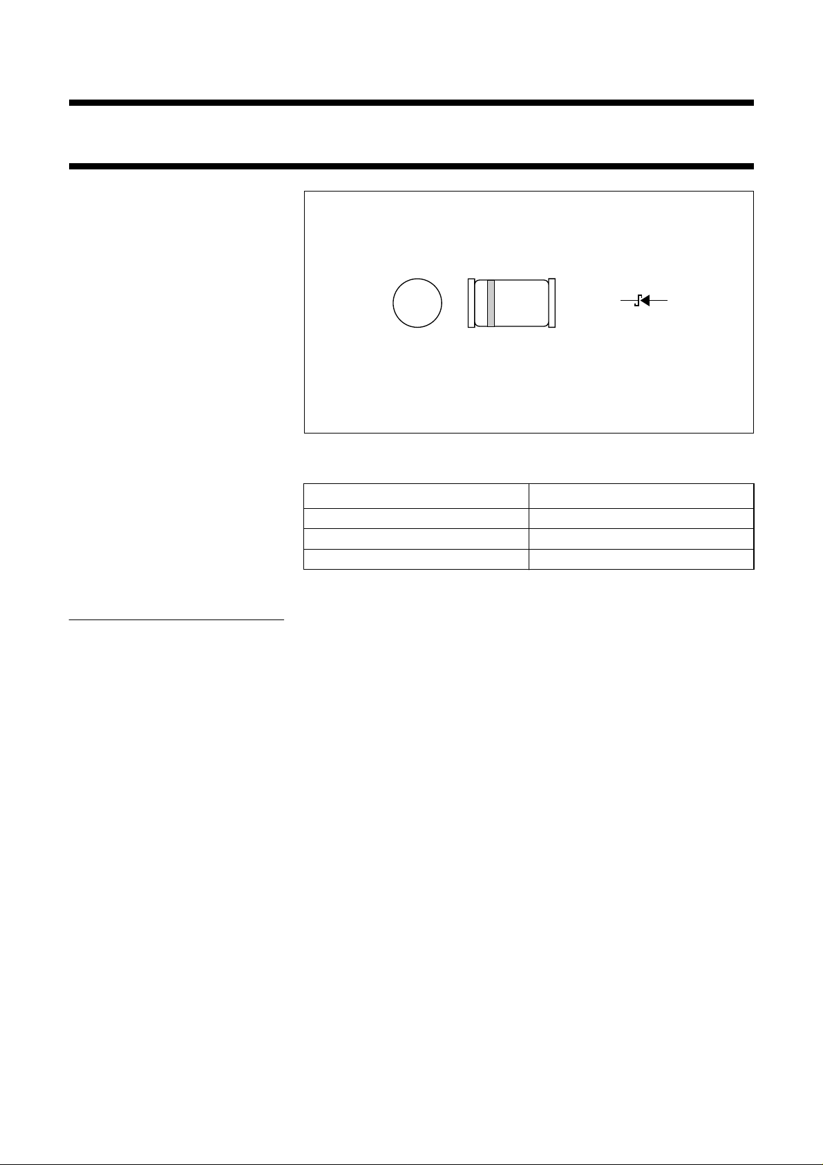
Fig.1 Simplified outline (SOD87) and symbol.
ka
MAM190
DESCRIPTION
The PRLL5817 to PRLL5819 types
are Schottky barrier diodes fabricated
in planar technology, and
encapsulated in SOD87 hermetically
sealed glass SMD packages
incorporating Implotec
TM(1)
technology.
(1) Implotec is a trademark of Philips.
MARKING
TYPE NUMBER MARKING CODE
PRLL5817 9
PRLL5818 9
PRLL5819 9
1999 Apr 22 2

Philips Semiconductors Product specification
Schottky barrier diodes PRLL5817; PRLL5818; PRLL5819
LIMITING VALUES
In accordance with the Absolute Maximum Rating System (IEC 134).
SYMBOL PARAMETER CONDITIONS MIN. MAX. UNIT
V
R
V
RSM
V
RRM
V
RWM
I
F(AV)
I
FSM
T
stg
T
j
continuous reverse voltage
PRLL5817
PRLL5818
PRLL5819
non-repetitive peak reverse voltage
PRLL5817
PRLL5818
PRLL5819
repetitive peak reverse voltage
PRLL5817
PRLL5818
PRLL5819
crest working reverse voltage
PRLL5817
PRLL5818
PRLL5819
average forward current T
=60°C −
amb
non-repetitive peak forward current t = 10 ms half sine wave;
Tj=T
prior to surge: VR=0
j max
storage temperature
junction temperature
−
−
−
−
−
−
−
−
−
−
−
−
−
−65
−
20 V
30 V
40 V
24 V
36 V
48 V
20 V
30 V
40 V
20 V
30 V
40 V
1A
25 A
+175 °C
125 °C
1999 Apr 22 3

Philips Semiconductors Product specification
Schottky barrier diodes PRLL5817; PRLL5818; PRLL5819
ELECTRICAL CHARACTERISTICS
T
=25°C unless otherwise specified.
amb
SYMBOL PARAMETER CONDITIONS MIN. TYP. MAX. UNIT
V
F
V
F
V
F
I
R
C
d
forward voltage see Fig.2
PRLL5817 I
= 0.1 A
F
I
=1A
F
=3A
I
F
forward voltage see Fig.2
PRLL5818 I
= 0.1 A
F
=1A
I
F
I
=3A
F
forward voltage see Fig.2
PRLL5819 I
reverse current VR=V
= 0.1 A
F
I
=1A
F
I
=3A
F
RRMmax
V
R=VRRMmax
; note 1
; Tj= 100 °C
diode capacitance VR= 4 V; f = 1 MHz
PRLL5817
PRLL5818
PRLL5819
−−
−−
−−
−−
−−
−−
−−
−−
−−
320
450
750
330
550
875
340
600
900
− 0.5 1
− 510
−
−
−
70
50
50
−
−
−
mV
mV
mV
mV
mV
mV
mV
mV
mV
mA
mA
pF
pF
pF
Note
1. Pulse test: t
= 300 µs; δ = 0.02.
p
THERMAL CHARACTERISTICS
SYMBOL PARAMETER CONDITIONS VALUE UNIT
R
th j-a
thermal resistance from junction to ambient note 1 150 K/W
Note
1. Refer to SOD87 standard mounting conditions.
1999 Apr 22 4
 Loading...