

Philips PREMIUM 10501 User Manual

Premium 10501 05-07-00
P10501A06.DOC User Manual Premium 10501
PHILIPS OPTICAL STORAGE
USER MANUAL
PREMIUM 10501
Philips Components

Premium 10501 05-07-00
P10501A06.DOC draft User Manual Premium 10501
Preface
This document gives some application information how to use the Premium 10501
The Starter kit Premium 10501 is intended to be used for high-end video/audio and Jukebox
applications. Using the kit and documentation should make it possible to provide a quickly start of the
design-in work.
The Premium 10501 is a complete functional module that consists of the CD engine, cables and
documentation. The CD engine is equipped with a PCB underneath the mechanism. The PCB contains
the electronics, and provides the necessary interface to connect the unit to the external application
circuit.
The unit can be controlled through the so-called DSA bus. Available DSA commands are described in
the Premium 10501 documentation. A floppy with DSA control software, which runs on an IBM
compatible PC, is available and is part of the documentation.
The Premium 10501 is not indented to be copied.
©Philips Electronics N.V. 2000
All rights reserved. Reproduction in whole or in part is prohibited without the written consent of the
copyright owner.
The information presented in this document does not form part of any quotation or contract, is believed
to be accurate and reliable and may be changed without notice. No liability will be accepted by the
publisher for any consequence of its use. Publication thereof does not convey nor imply any license
under patent- or other industrial or intellectual property rights.
Philips components © 2000 Philips Electronics N.V. All rights reserved Page 2

Premium 10501 05-07-00
P10501A06.DOC draft User Manual Premium 10501
PHILIPS LASER OPTICS
USER MANUAL
PREMIUM 10501
Author(s)
Phil Wu Arthur He
Philips Components
Optical Storage Shanghai
Keywords:
High-end Audio
Jukebox
DSA
CD10
VAU1254
Premium 10501
Note:
The publisher reserve the right to change the data mentioned in this document without prior notice.
Philips components © 2000 Philips Electronics N.V. All rights reserved Page 3

Premium 10501 05-07-00
P10501A06.DOC draft User Manual Premium 10501
Revision history
Version Date Remarks
Version 0.1
draft version
05-07-00
Philips components © 2000 Philips Electronics N.V. All rights reserved Page 4

Premium 10501 05-07-00
P10501A06.DOC draft User Manual Premium 10501
Table of Contents
1. Introduction ...........................................................................................................................................................6
1.1 Abbreviations used........................................................................................................................................6
2. System overview...................................................................................................................................................6
2.1 Features............................................................................................................................................................7
2.2 Some numbers ................................................................................................................................................7
3. PCB key component and connector placement...............................................................................................8
4. Configuration options..........................................................................................................................................8
5. PCB connector interface description.................................................................................................................9
5.1 The actuator connector (internal connection)...........................................................................................9
5.2 The diode flex connector (internal connection) ........................................................................................9
5.3 The DSA connector.....................................................................................................................................10
5.4 The I2S/graphics connector.......................................................................................................................10
5.5 The EBU connector.....................................................................................................................................11
5.6 The power connector ...................................................................................................................................11
5.7 The line-out connector................................................................................................................................12
5.8 The 16 MHz clock output..........................................................................................................................12
6. The DSA control interface................................................................................................................................12
6.1 DSA interface bus protocol........................................................................................................................13
6.2 DSA Commands..........................................................................................................................................13
6.3 Summary of DSA Control commands.....................................................................................................14
7. Micro Controller pinning..................................................................................................................................15
7.1 General...........................................................................................................................................................15
7.2 Features..........................................................................................................................................................15
7.3 Micro controller Pinning.............................................................................................................................15
8. Power requirements ...........................................................................................................................................17
8.1 Switching the power on /off.......................................................................................................................17
8.2 Rise time of the power supplies ................................................................................................................17
8.3 Ventilation.....................................................................................................................................................17
9. Getting the best audio performance.................................................................................................................18
9.1 Absolute audio phase..................................................................................................................................18
10. Connecting the Premium 10501.....................................................................................................................19
11. Problem solving. ...............................................................................................................................................20
12. General application information .................................................................................................................... 20
Philips components © 2000 Philips Electronics N.V. All rights reserved Page 5
Premium 10501 05-07-00
P10501A06.DOC draft User Manual Premium 10501
1. Introduction
Using the Premium 10501 module, the user will get a high performance CD-engine, which is designed
to deliver an extremely good playability and very low mechanical playing noise.
The module provides standard to high end audio quality output signals. For those customers who strive
for extreme high performance audio, fine tuning the audio output with additional post filtering can be
used. Using a special external DAC is still possible as the I2S signals are available.
Refer for all technical specifications to the data sheets only
1.1 Abbreviations used
BCCDAC Bitstream Continuous Calibration Digital to Analog Converter
CD Compact Disc
CD-DA Compact Di sc Digital Audio
CD10 SAA7324 Compact Disc Decoder & Digital Servo
DAC Digital to Analog Converter
DSA Data Strobe Acknowledge
EBU European Broadcast Union
HF High frequency (EFM) signal
LDGU Laser Detector Grating Unit
OTP One-time Programmable (Eprom controller).
QFP Quad Flat Pack
VAM Video Audio Module (CD Mechanism)
VAU Video Audio Unit (Assembly of VAM and PCB)
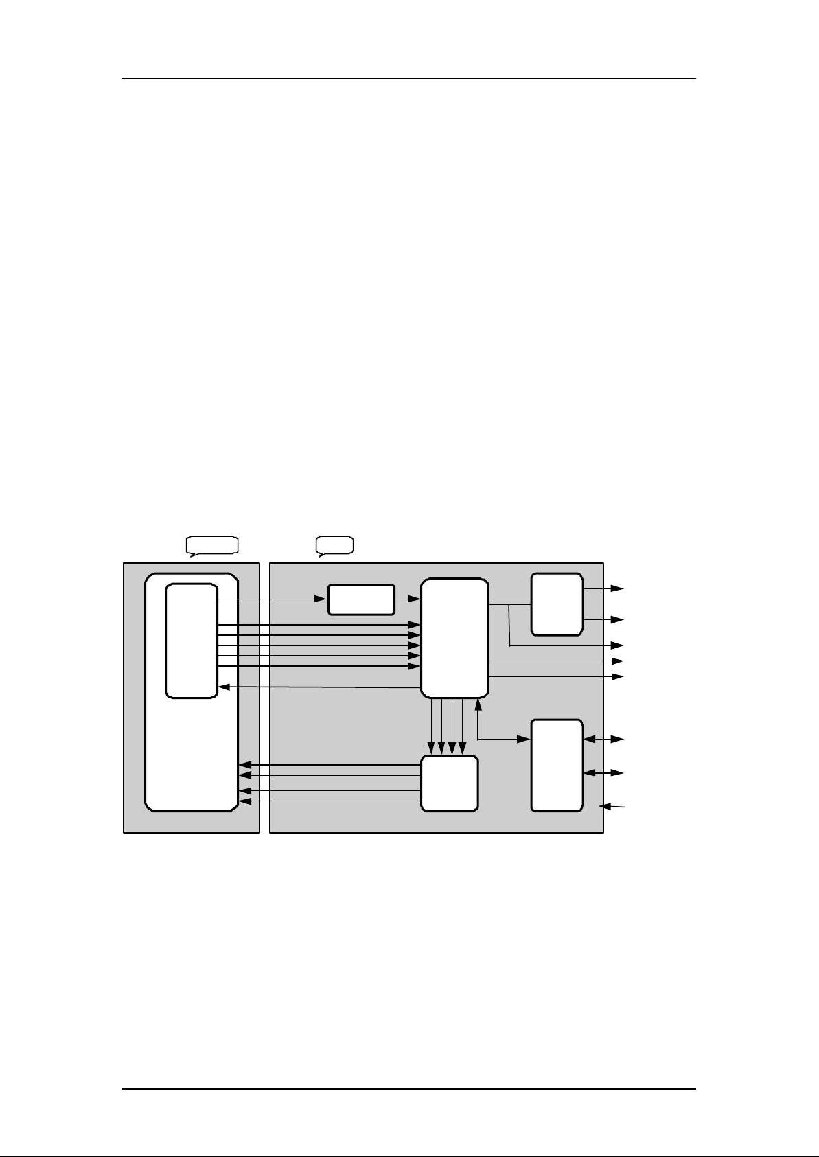
2. System overview
HF signal
Diode
Amplifier
Laser
Supply
TZA1022
VAM1254
3-beam
Mechanism
Figure 1: Block diagram
LF signals
Laser on/off
PCBMechanism
HF Equalizer
Discrete circuit
Digital
Servo
Control
and
CD-Decoder
SAA7324 M2
Sle
Foc
usRadial
dgeMotor
2 x
Dual Servo
Drivers
TDA7073
Control
Stereo
DAC
TDA1305T
Micro
Controller
Left audio
Right audio
I2S
IEC958
16MHz optional
DSA control
Flash interface
Supply
The left part of this diagram shows the VAM1254 mechanism. The total assembly of VAM1254 and
the PCB is called the CD Engine. The Premium 10501 starterkit consist of the CD engine, some cables,
DSA interface, control software on floppy and documentation.
Philips components © 2000 Philips Electronics N.V. All rights reserved Page 6
 Loading...