

Page 1
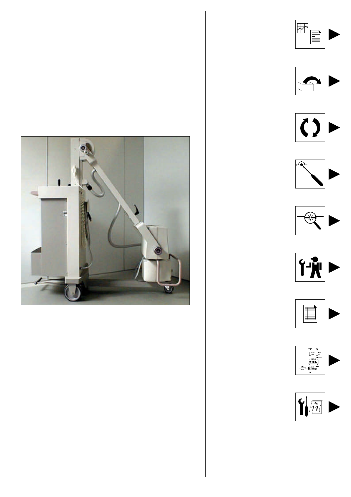
PRACTIX 100 PLUS
1.Technical data &
labels
code: W3004_Rev0
SERVICE MANUAL
2. Installation &
Acceptance
code: W3006_Rev0
3. Replacement
code: W3010_Rev0
4. Adjustments
code: W3012_Rev0
5. Faults finding
code: W3014_Rev0
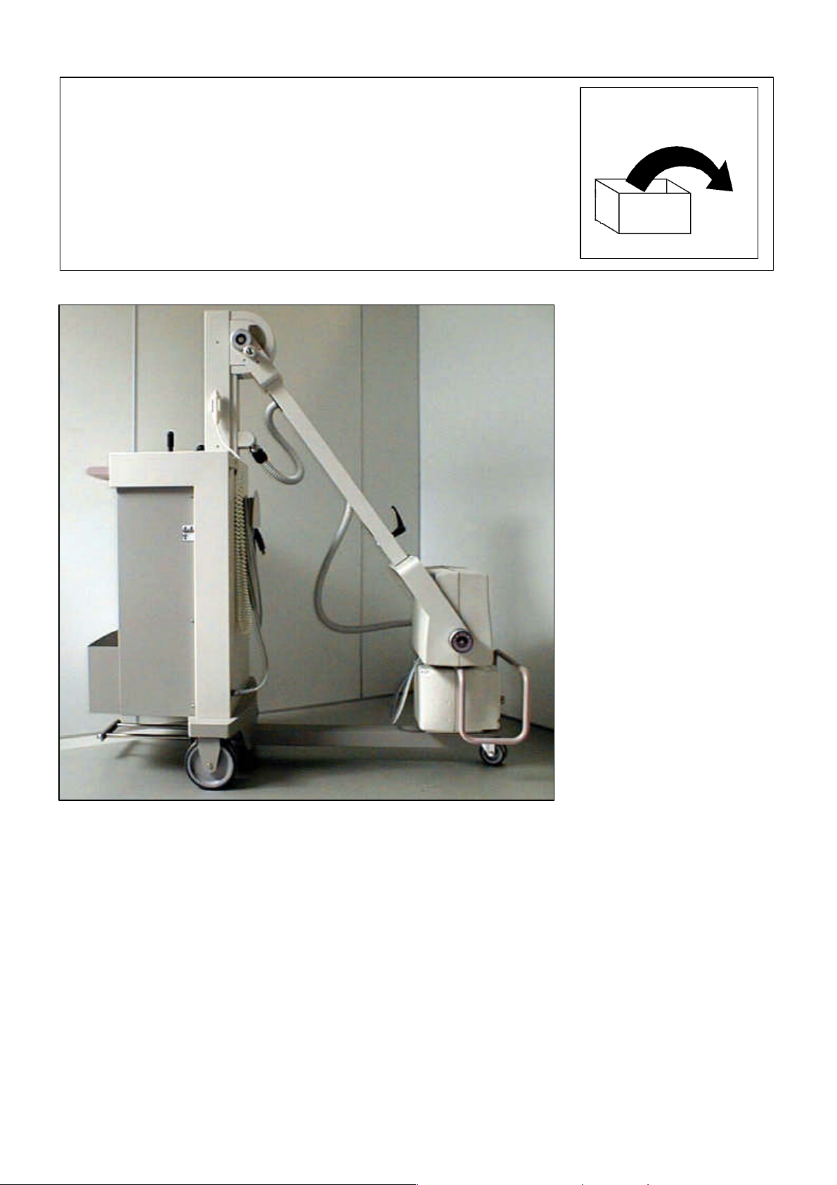
Practix 100 plus
PMS 12NC: 9890-010-81791
Date:
Service manual
PMS 12NC: 4512-984-22741
File name: W3000_Rev1.doc
6. Service information
code:W3016_Rev0
7. Parts list
code: W3018_Rev1
8. Electrical drawings
code: W3020_Rev0
9. Programmed
maintenance
code: W3022_Rev0
****
Page 2
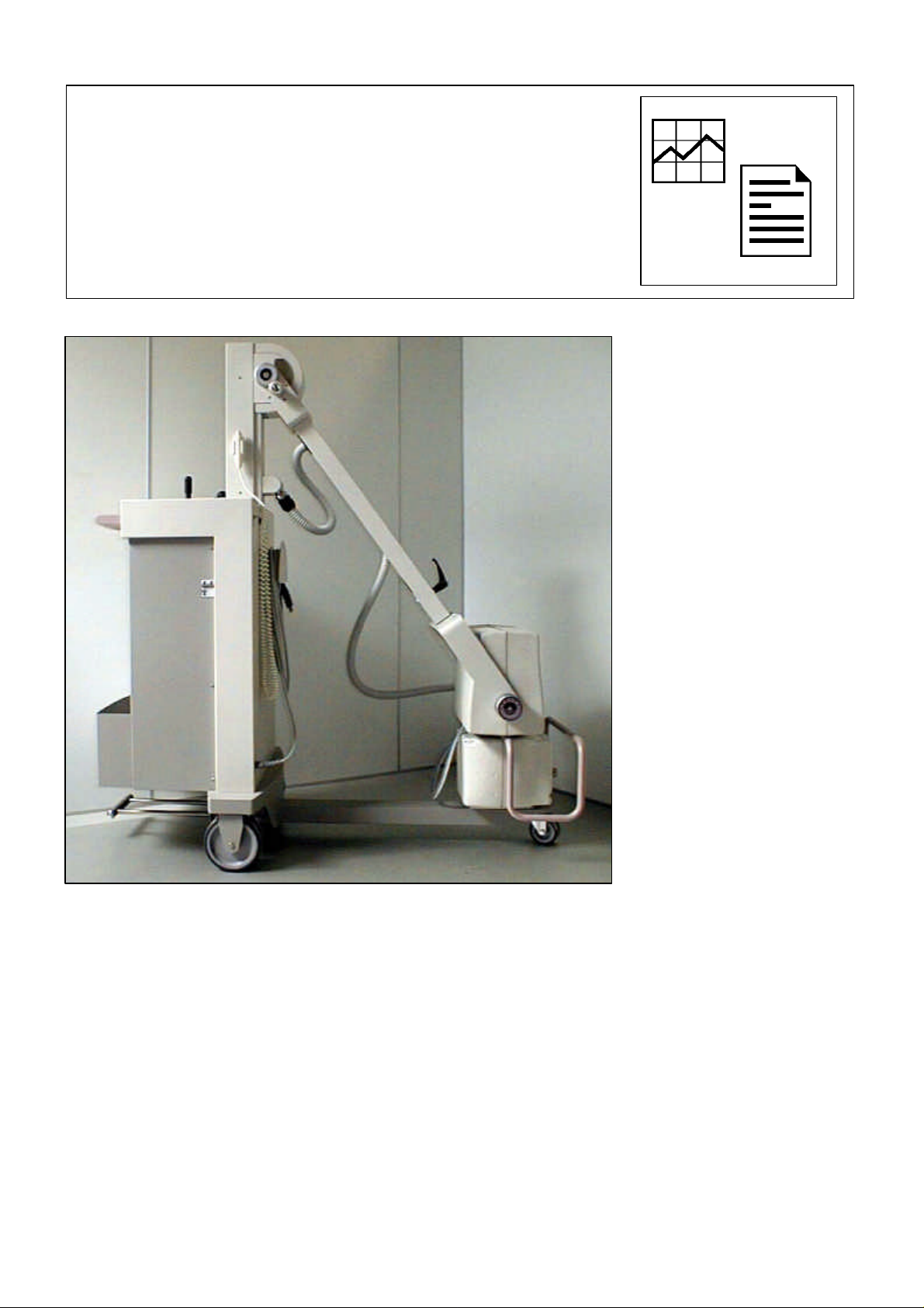
PRACTIX 100 PLUS
TECHNICAL DATA &
LABELS
[File: W3004_Rev0.doc]
Page 3

PRACTIX 100 plus Technical data & labels
SUMMARY
TECHNICAL DATA 2
Electrical characteristics...................................................................................................................... 2
Radiological characteristics.................................................................................................................. 2
Monobloc........................................................................................................................................... 3
Collimator.......................................................................................................................................... 3
Environmental data ............................................................................................................................ 3
Operative modes................................................................................................................................ 4
Functionality ...................................................................................................................................... 4
Accessories and options...................................................................................................................... 4
Mechanical characteristics................................................................................................................... 5
Unit volume sizes ............................................................................................................................... 6
MHF 2011 Monobloc........................................................................................................................... 7
Tube characteristics............................................................................................................................ 8
LABELS 10
STANDARDS AND DIRECTIVES COMPLIANCE 11
[File: W3004_Rev0.doc] 1/12
Page 4

PRACTIX 100 plus Technical data & labels
TECHNICAL DATA
Electrical characteristics
Description Data
Voltage
Frequency
Absorbed current
Line compensation
Line resistance
Standard plug
Classification
Use conditions
The unit is not suitable to the use where danger of mixtures inflammable with air or nitrous oxide
exists.
115/230Vac ±10% Standard monophase with automatic
unit predisposition in function of the mains line
50/60Hz standard
9A max. peak in radiography @ 230Vac
Automatic
<1Ω @230Vac
< 1Ω @115Vac
16A @230Vac
Class I, applied parts type B
Continuos functioning with intermitting load
Radiological characteristics
Description Data
Generator power in DC current
Inverter frequency
Max. Ripple
Rise time
kV Range
mA range
@115/230Vac
mAs range in function of kV
@115/230Vac
11kW @100Kv
20kHz
<1% @100kV
<2ms @100kV
40 ÷ 125kVp in step of 1kV
kV
40 140mA 70mA 70mA
50 140mA 70mA 70mA
60 130mA 65mA 65mA
70 125mA 63mA 63mA
80 120mA 60mA 60mA
90 115mA 58mA 58mA
100 110mA 55mA 55mA
110 90mA 45mA 45mA
120 80mA 40mA 40mA
125 75mA 38mA 38mA
0,2 ÷÷ 125mAs in 57 steps with 12,5% inc.
From:
mAs>0,63 mAs<0,63
(t<100ms)
MODE1
40 ÷ 42kV 0,2 ÷ 125mAs
43 ÷ 62kV 0,2 ÷ 100mAs
63 ÷ 72kV 0,2 ÷ 80mAs
73 ÷ 102kV 0,2 ÷ 63mAs
103 ÷ 125kV 0,2 ÷ 50mAs
mA
(t>100ms)
MODE2
MODE2
[File: W3004_Rev0.doc] 2/12
Page 5

PRACTIX 100 plus Technical data & labels
Monobloc
Description Data
Monobloc type
Weight
X-ray tube type
Anode
Focus nominal extension according to IEC 336
Nominal anodic power (for 1 sec.)
Anode thermal capacity
Anode disk diameter
Anode inclination
Max. continuos thermal dissipation of the anode
Max. anode cooling speed
Monobloc thermal capacity
Max. continuos thermal dissipation of monobloc
Total filtration
Leakage radiation
Loading, heating, and cooling curves
H.V. transformer isolation
MHF 2011
19kg.
IAE X20P
Rotating (2850rpm @ 50Hz) (3400rpm @ 60Hz)
0.8mm small focus
11kW small focus
50kJ (67kHU)
64mm
17,5°
175W
13kJ/min (17,5kHU/min)
600kJ (800kHU)
55W
2.7mm Al
<1mGy/h second IEC 601-1-3
Please refer to the enclosed diagrams
Oil bath
Collimator
Description Data
Type, brand and model
Collimation
Brightness source
Field covering
Brightness intensity
Contrast ratio
Focus film distance measure
Inherent filtration
Rotation
Weight
Accessories
Manual with internal luminous source (Ralco P 232)
Square field, multilayers
Halogen lamp 12V 100W with temporized ignition of approx. 30s
43 x 43cm at focus film distance of 1m
160lux at focus film distance of 1m
4:1
Extractable Meter
2mm Al
±130°
8.4Kg.
Predisposition of the ionization chamber insertion
Environmental data
Description Normal use Transport and warehouse
Temperature
Relative humidity
Pressure
From +10°C to +40°C From -25°C to +70°C
From 30% to 75% not condensing From 10% to 90% not condensing
From 700 to 1060hPa From 500 to 1060hPa
[File: W3004_Rev0.doc] 3/12
Page 6
PRACTIX 100 plus Technical data & labels
Operative modes
Mode Characteristic Performances
Radiography
Working Mode At 2 points with kV and mAs setting
APR Anatomic Mode Memorization of 32 exams, (4 programs,
each of 8 exam) available in the 4 selectable
languages
Small focus in any operating status 0,8mm
kV variation range
mA variation range @115/230Vac
mAs variation range @115/230Vac
Times range @115/230Vac
Exposure control Constant kV and mA during the whole
Use coefficient (duty cycle) 1:40
40 ÷ 125kV in step of 1kV
38 ÷ 140mA associated in automatic to kV
0,2 ÷ 125mAs in 57 steps with 12,5%
increases
0,0025 ÷ 2s in function of the set mAs
exposure
Functionality
Description Data
User’s interface
Selectable languages
Radiography control
Safeties
Keyboard with display (alphanumeric LCD, 4 lines x 20 characters) for
every operating parameter and message of eventual anomalies.
Service program for faults finding.
Microcontroller management.
English, French, German and Spanish, by a configuration program.
Push-button with extractendible cable. It’s shown the use of last kV value
set in manual mode or APR.
Upon the ignition the unit is set in manual mode with default values.
Filament current.
Monobloc temperature.
Max. load exceeded.
Max. kV or H.V. fault.
Memory data check.
Microcontroller auto test
Accessories and options
Description 12NC
X-ray control with extendible cable
Infrared X-ray control, model RAYMOTE III
Ionizing chamber dosimeter, model DIAMENTOR PX
4512-535-39761 Standard
9890-010-82071 Optional
9890-010-81141 Optional
[File: W3004_Rev0.doc] 4/12
Page 7

PRACTIX 100 plus Technical data & labels
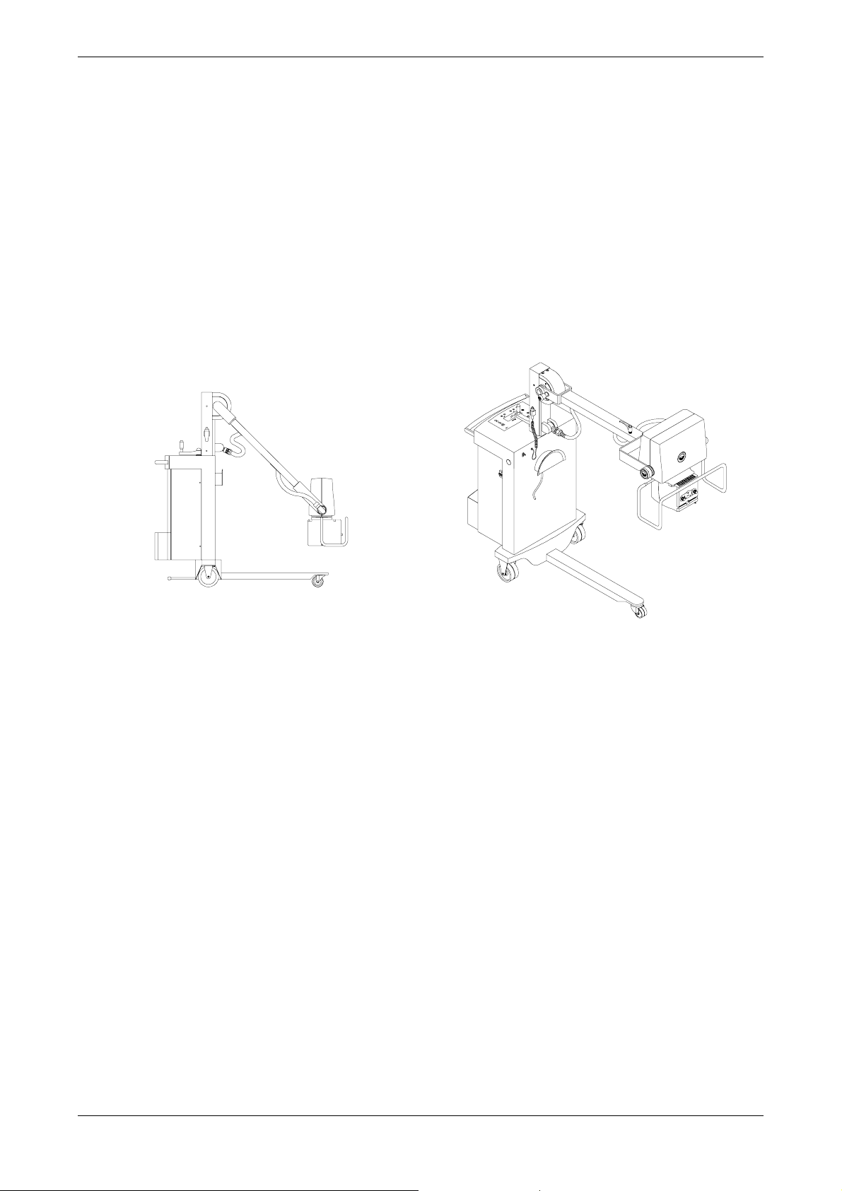
Mechanical characteristics
Description Data
Weight
Max. width
Length in transport position
Max. height in transport position
Max. height with arm at the max. extension
Control console height
Focus-floor distance
Arm rotation around the vertical axis
Monobloc rotation around the arm axis
Monobloc rotation around its axis
Max. height of the unit front leg
Cassette holder
Movement
Wheels diameter
Please refer to the drawing enclosed
170kg approx.
670mm
1277mm
1438mm
2258mm
970mm
456 ÷ 2018mm
n.d.
±180°
153° (+104° ÷ -49° towards the vertical axis)
105mm
5 cassettes, 35 x 43cm format
Manual.
Double front swiveling wheel.
Double rear wheels driven by the handle placed
on the unit stand near the console.
Stationary brake activation by the same handle
for the rear wheels driving.
Tilting pedal (obstacles over passing).
Rear: double wheel 150mm width 30mm
Front: double wheel 80mm width 25mm
[File: W3004_Rev0.doc] 5/12
Page 8
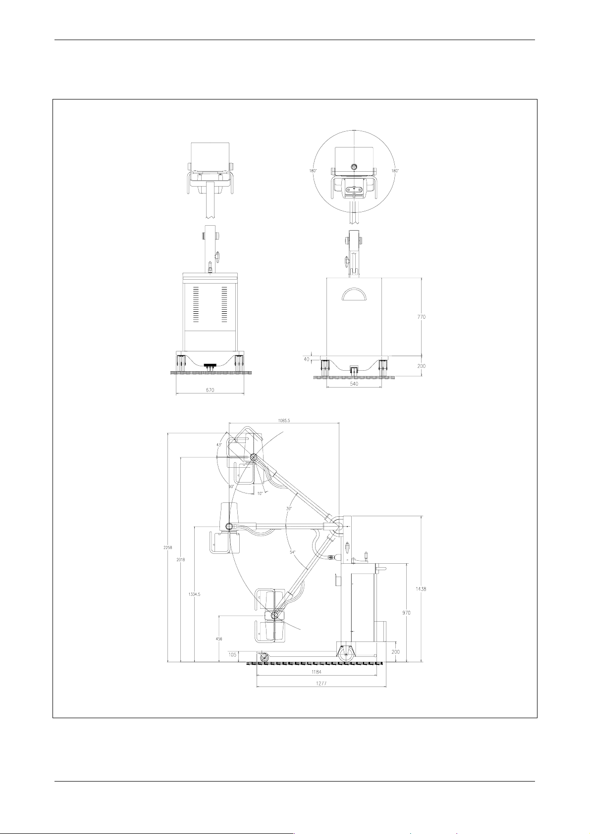
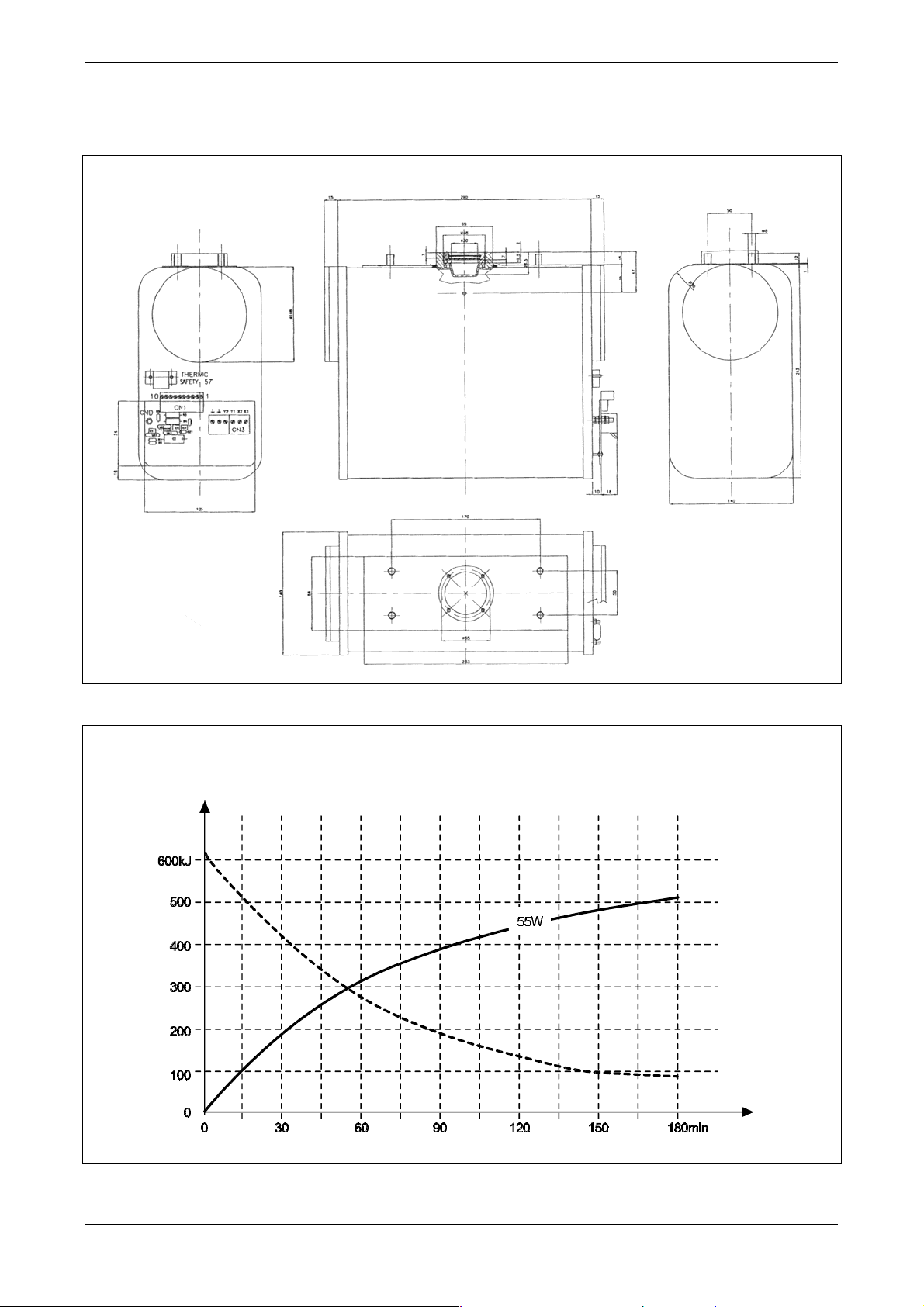
Unit volume sizes
PRACTIX 100 plus Technical data & labels
[File: W3004_Rev0.doc] 6/12
Page 9
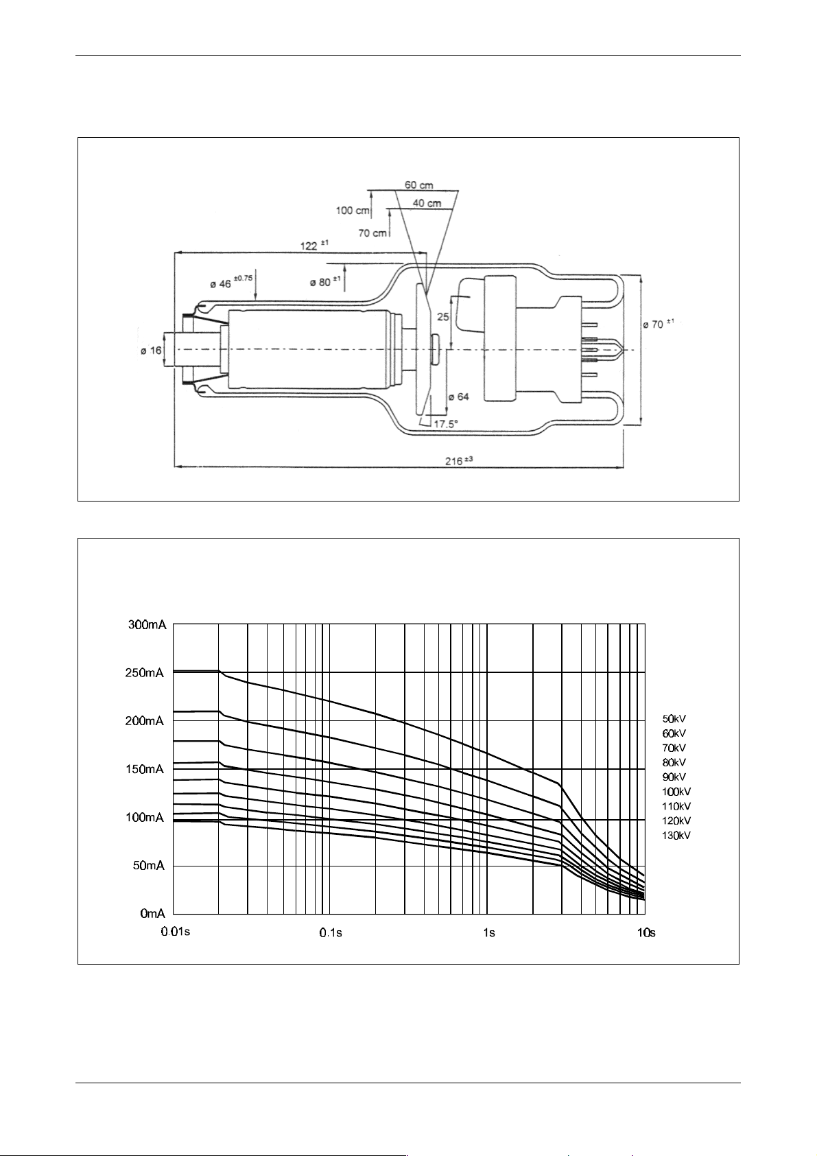
MHF 2011 Monobloc
PRACTIX 100 plus Technical data & labels
Sizes
Monobloc cooling and heating curves
Stored energy (kJ) / Time (min)
[File: W3004_Rev0.doc] 7/12
Page 10
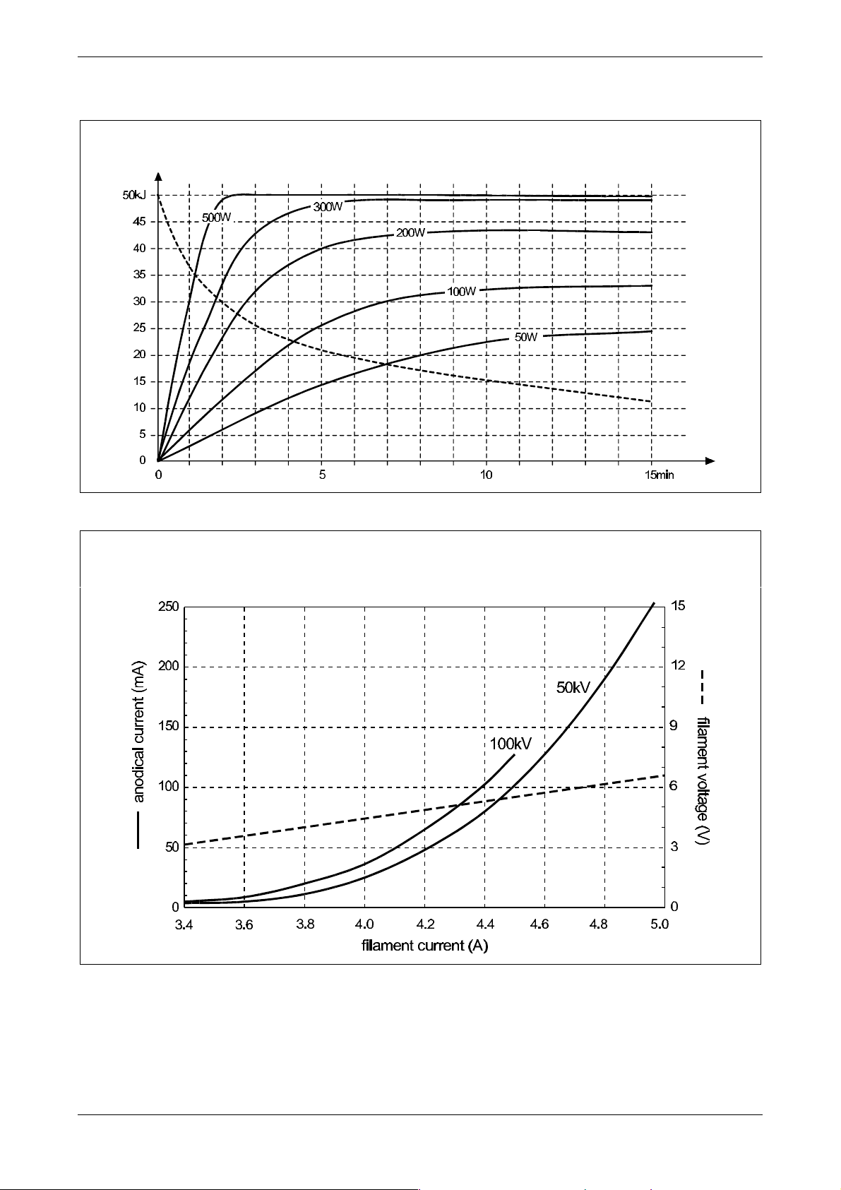
Tube characteristics
PRACTIX 100 plus Technical data & labels
Sizes
Single load rating
0.8 - 3~ - 3000min
-1
Tube current (mA) / Time. (sec)
[File: W3004_Rev0.doc] 8/12
Page 11
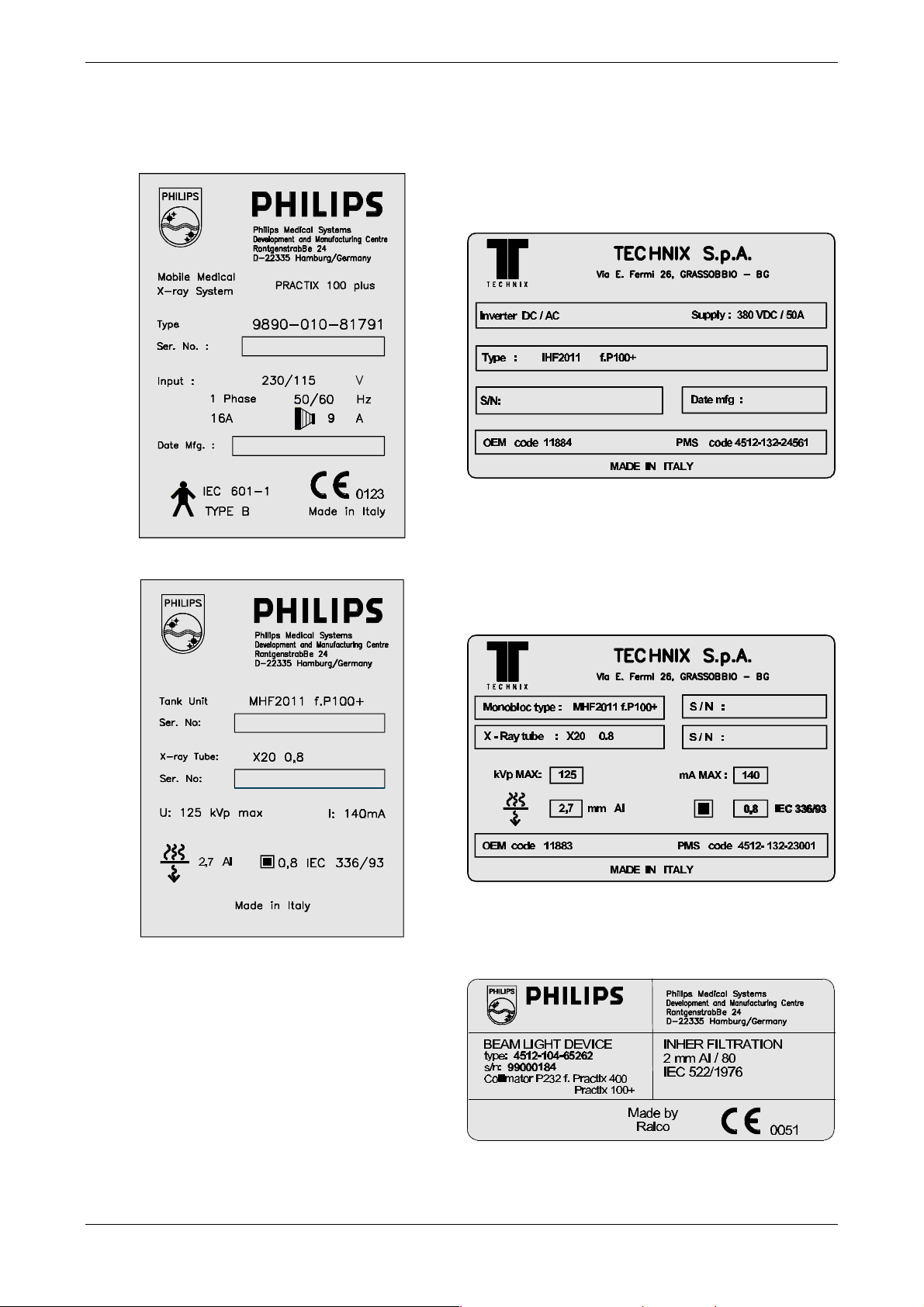
PRACTIX 100 plus Technical data & labels
Anodical cooling and warming curves
Stored energy (kJ) / Time (min)
Filament emission curve
Filament current / Anodical current (mA)
Filament current / Filament voltage (V)
[File: W3004_Rev0.doc] 9/12
Page 12
LABELS
PRACTIX 100 plus Technical data & labels
inverter label
unit label
monobloc external label
monobloc internal label
collimator label
[File: W3004_Rev0.doc] 10/12
Page 13

PRACTIX 100 plus Technical data & labels
STANDARDS AND DIRECTIVES COMPLIANCE
Reference Description
MDD 93/42/EEC
89/336/EEC
EN IEC 60601-1
EN IEC 60601-1-2
EN IEC 60601-1-3
EN IEC 60601-1-4
EN IEC 60601-2-7
EN IEC 60601-2-28
EN 1441
IEC 336
UL 187
FDA
CDHR
CSA
Medical Devices Directive (CE mark)
Electromagnetic compatibility
Medical devices safety
Electromagnetic compatibility
Protection against ionizing radiation
Software safety
High voltage generators
X-ray tube assemblies – housing
Risk analysis
X-ray tubes focus
USA standard
USA standard
USA standard
Canada standard
[File: W3004_Rev0.doc] 11/12
Page 14

PRACTIX 100 plus Technical data & labels
DOCUMENT STATUS
Rev. Date Page/s Modifiction description
0 Document approval
1
2
3
4
5
[File: W3004_Rev0.doc] 12/12
Page 15
PRACTIX 100 PLUS
INSTALLATION &
ACCEPTANCE
[File: W3006_Rev0.doc]
Page 16

PRACTIX 100 plus Installation & Acceptance
SUMMARY
HOW TO PROCEED 2
PRELIMINARY INFORMATION 3
UNIT UNPACKING 4
Unpacking procedure.......................................................................................................................... 4
Packing and content description.......................................................................................................... 7
SIGHT CHECK OF THE UNIT INTEGRITY 8
PRELIMINARY KNOWLEDGES 8
MECHANICAL TESTS 9
UNIT SUPPLY 11
Preliminary operations...................................................................................................................... 11
Mains connection.............................................................................................................................. 11
ELECTRICAL TESTS (NO IRRADIATION) 12
Ignition - Start up - Ready ................................................................................................................ 12
Collimator check............................................................................................................................... 12
Data setting and preparation check ................................................................................................... 12
TUBE PREPARATION 13
ACCURACY TEST 14
Output data check............................................................................................................................ 14
X-ray irradiation field check............................................................................................................... 15
UNIT CONFIGURATION 16
Default configuration........................................................................................................................ 16
Customer’s configuration .................................................................................................................. 16
Configuration sheet...................................................................................................................... 17
Configuration ................................................................................................................................... 18
Date and time setting....................................................................................................................... 18
[File: W3006_Rev0.doc] 1 / 19
Page 17
PRACTIX 100 plus Installation & Acceptance
HOW TO PROCEED
For the proper and safe unit installation please follow, step by step, the INSTALLATION
SHEET. Proceed with the next operation ONLY once the previous steps have been properly
completed.
INSTALLATION SHEET
1. Preliminary knowledges and information KK yes KK no
2. Unpacking and content verification KK yes KK no
3. Sight check of the unit integrity * KK yes KK no
4. Reading of the chapter “Service information” KK yes KK no
5. Mechanical tests* KK yes KK no
6. Check of the unit compatibility with mains KK yes KK no
7. Electrical tests (do not perform x-ray)* KK yes KK no
8. X-ray tube preparation* KK yes KK no
9. X-ray tests* KK yes KK no
10. Request of data configuration to the user KK yes KK no
11. Unit configuration KK yes KK no
☺☺
12. Now the unit is ready for the use
!!EUREKA!!
* Acceptance phase
[File: W3006_Rev0.doc] 2 / 19
Page 18
PRACTIX 100 plus Installation & Acceptance
PRELIMINARY INFORMATION
This unit has been assembled and checked in factory following methods certified both for
production and testing. The same methods are in compliance with the most recent international
Standards and with the European Directive for Medical Devices (93/42 CEE).
During checking phase it is draught a Test Report including the following information is draught:
• Output data accuracy (kV-mA-time) test
• Light field X-ray field conformity test
• Electrical safety (PE resistance and leaked currents)
To ensure the unit safety and efficiency even during the transport between firm and user, some
tests and functional checks are required. It is necessary to perform those tests upon installation.
To check the output data, therefore kV and X-ray time measurements, the use of non-invasive
tools is required. Should tools be not available, check these values on the unit display directly (see
next pages).
Perform what described in this chapter, even if additional and specific acceptance
tests are required
(i.e. by hospital or Government).
DO NOT PERFORM HAZARDOUS OPERATIONS
ELECTICAL SHOCK DANGER
Even if the mains plug is disconnected a dangerous voltage can be
present inside the unit in case the
completely discharged.
capacitors battery is not
PERFORM THE DISCHARGE PROCEDURE
Before removing the Plexiglas protection or performing any
operation on Capacitors Battery, Power Unit
Circuits and Monobloc it is necessary to discharge the capacitors
battery.
THE DISCHARG
“Faults finding”.
E PROCEDURE IS DESCRIBED IN THE CHAPTER
, Inverter Power
[File: W3006_Rev0.doc] 3 / 19
Page 19
PRACTIX 100 plus Installation & Acceptance
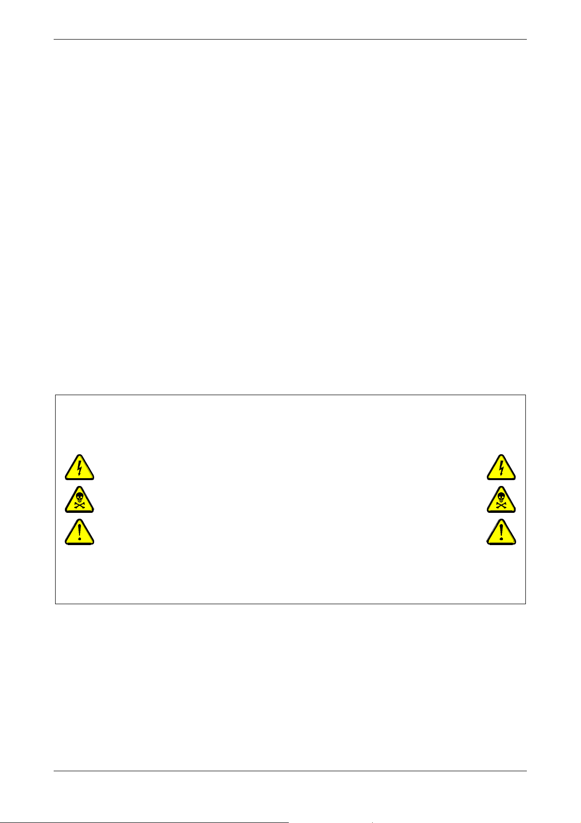
UNIT UNPACKING
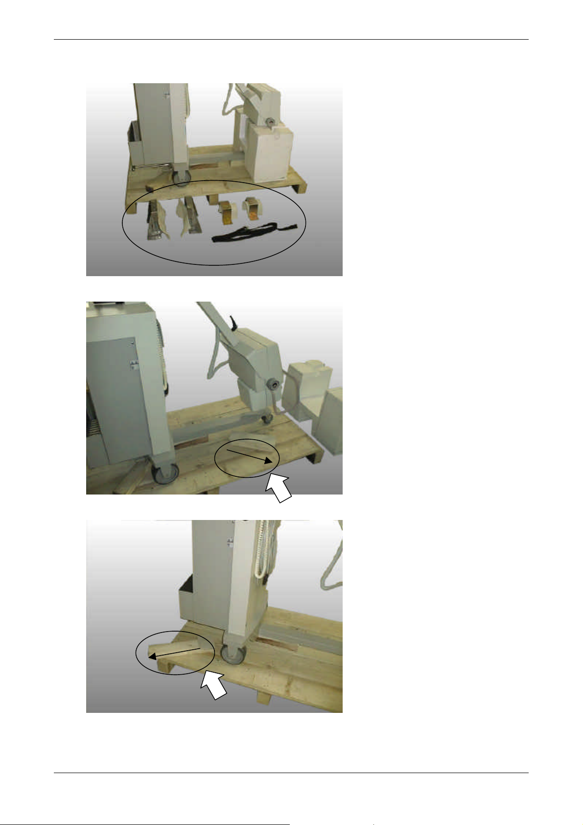
Unpacking procedure
This procedure requires a two operators intervention. For its performance, it is necessary to
use a fork key ø17mm to remove clamps and a screwdriver to remove the packing screws.
1.
Remove the packing cover.
2. Loosen the nuts which fix the clamps and remove the arm belt.
[File: W3006_Rev0.doc] 4 / 19
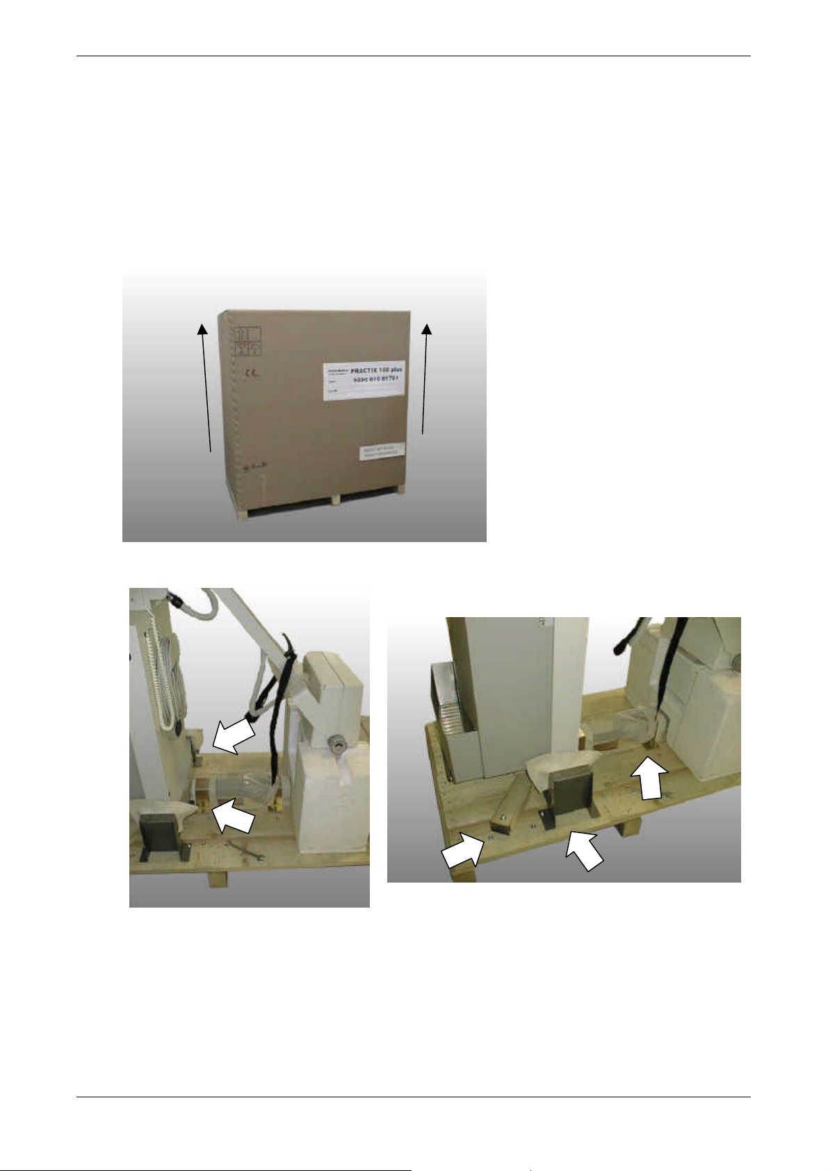
Page 20
PRACTIX 100 plus Installation & Acceptance
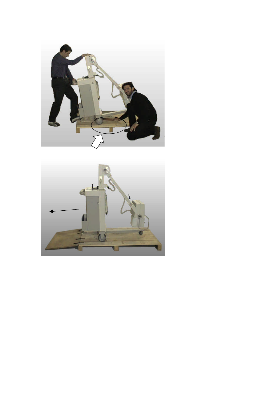
3. Remove every clamp.
4. Remove the polystyrene protecting the monobloc and the anterior wood block .
5. Remove the posterior wood block.
[File: W3006_Rev0.doc] 5 / 19
Page 21
PRACTIX 100 plus Installation & Acceptance
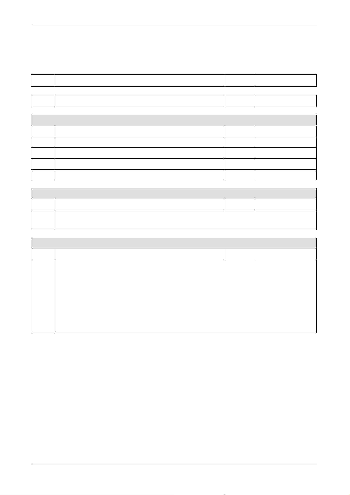
6. Act on the tilting lever and arise the unit frontal part, remove the central wood block.
7. Then, by using the skid, operate very carefully and remove the unit from the pallet.
[File: W3006_Rev0.doc] 6 / 19
Page 22
PRACTIX 100 plus Installation & Acceptance
Packing and content description
The packing includes:
q.ty description TX cod. 12NC
1 PRACTIX 100 plus 62915 9890-010-81791
Manuals
1 User’s manual in English language 4512-109-23042
1 User’s manual in German language 4512-109-23041
1 User’s manual in French language 4512-109-23043
1 User’s manual in Spanish language 4512-109-23044
1 Service manual (english) X3000 4512-984-22741
Paints
1 Touch kit paints composed by: 62428 4512-535-39211
1 Gray SF8758
1 Pink SF8582
1 Mushroom SF6998
Parts
1 Spare parts set composed by: 62918 4512-132-23131
1 Halogen lamp 12V - 100W 11449 4512-535-38731
1 Fuse 5x20 T 250mA / 250V 11361 4512-132-23141
1 Fuse 5x20 T 500mA / 250V 11288 4512-535-37301
1 Fuse 5x20 T 1A / 250V 11289 4512-535-37291
2 Fuse 5x20 T 4A / 250V 11292 4512-535-37331
1 Fuse 5x20 T 10A / 250V 11150 4512-535-37271
2 Ceramic extrafast fuse 10x38 20A - gR/ 600V 11917 4512-132-23151
2 Extrafast fuse 63A - ETF / 660V 11456 4512-132-23161
4 Support for board locking EHCBS - 6 (h=10mm) 11872 4512-132-24361
2 Support for board locking EHCBS - 16 (h=25mm) 11867 4512-132-23181
4 Cables medium clip 150x3,6mm 11234 4512-535-23191
[File: W3006_Rev0.doc] 7 / 19
Page 23
PRACTIX 100 plus Installation & Acceptance
SIGHT CHECK OF THE UNIT INTEGRITY
After the unpacking phase perform the following checks:
1. Labels
2. Covers painting
3. Keyboard
4.
Collimator and monobloc
5. Handles
6. Mains cable
7. X-ray button and button cable
8. Generator-monobloc-collimator connecting cable
PRELIMINARY KNOWLEDGES
Before proceeding with the unit installation the technician has to carefully read the chapter
“Service information”
. It includes several useful information to perform the installation properly.
[File: W3006_Rev0.doc] 8 / 19
Page 24
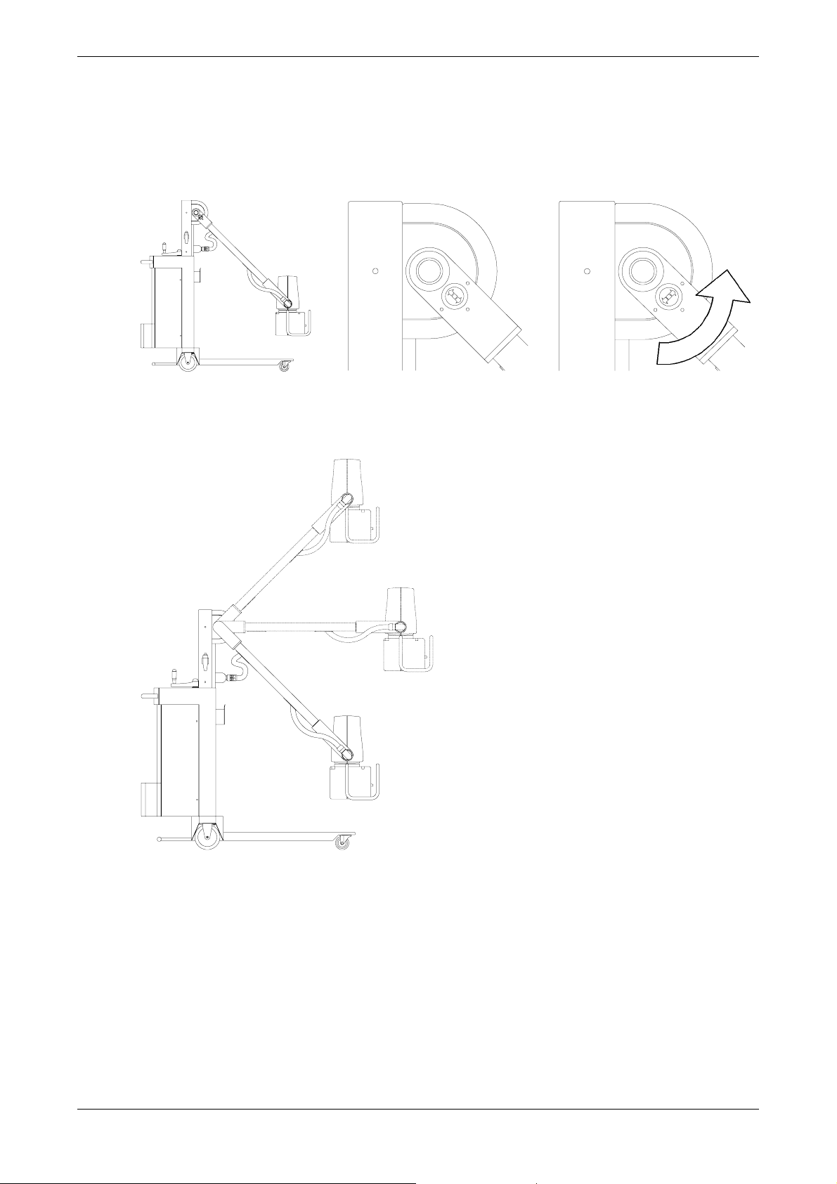
MECHANICAL TESTS
Move the unit from the parking condition (unlock the arm) by pulling and rotating (90°.) the release
1.
pawl.
parking position locked arm unlocked arm
Check the arm movement and balancing in every operative position, as shown in the picture.
2.
PRACTIX 100 plus Installation & Acceptance
[File: W3006_Rev0.doc] 9 / 19
Page 25
PRACTIX 100 plus Installation & Acceptance
Check the monobloc group balancing and rotation towards the longitudinal axis.
3.
Unlock the monobloc brake and check the monobloc group rotation (±180°) around the horizontal
4.
axis. Furthermore check the right gonimeter indication.
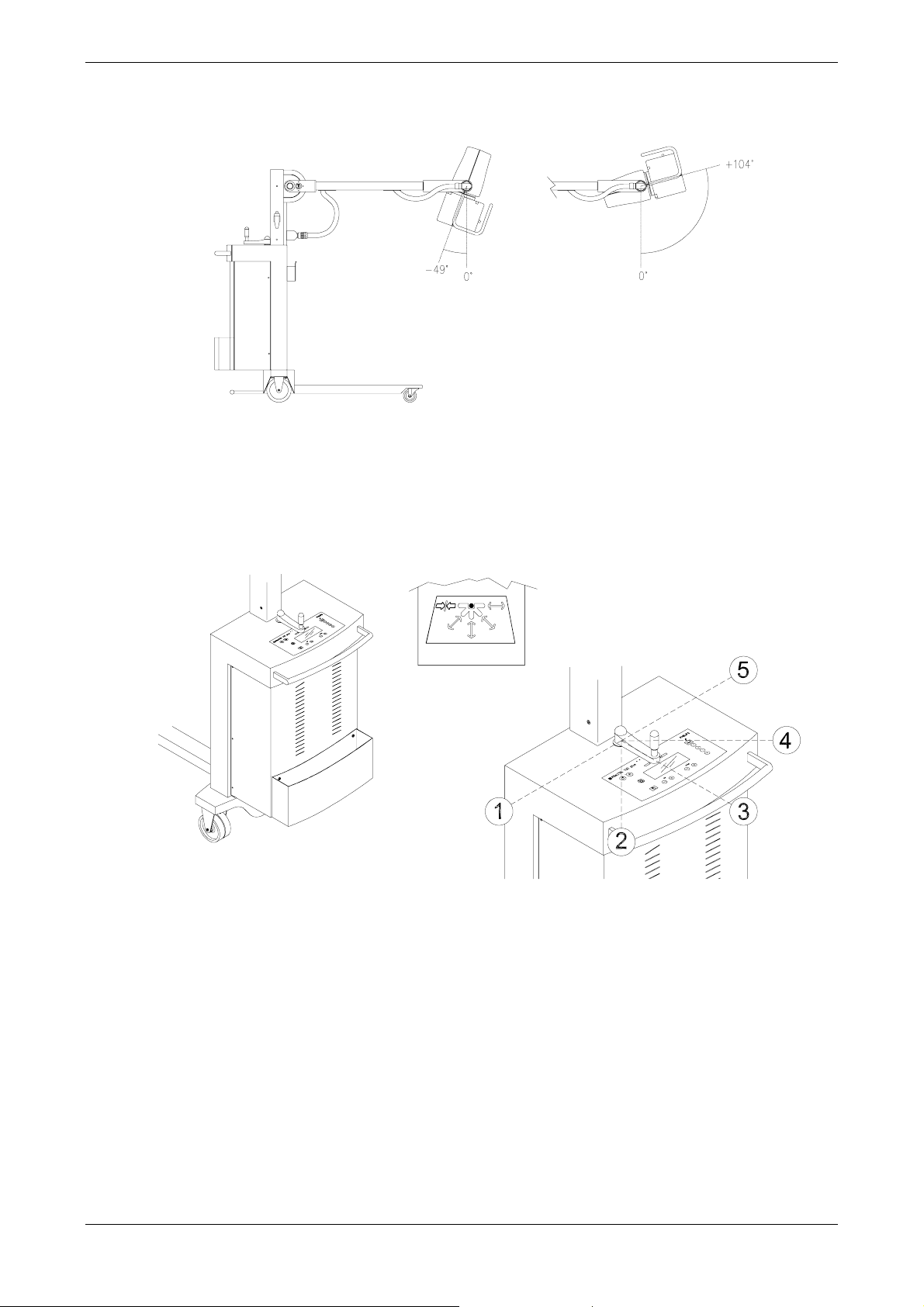
Check the proper collimator rotation around his vertical axis (±135°).
5.
Check the stationary brake and the directional handle.
6.
Place the handle in the following positions (refer to the label attached on the arm column) and check
the proper functioning:
• pos. 1: brake ON
• pos. 2: oblique left-right motion
• pos. 3: backward-forward motion
• pos. 4: oblique right-left motion
• pos. 5: left-right motion
[File: W3006_Rev0.doc] 10 / 19
Page 26

PRACTIX 100 plus Installation & Acceptance
UNIT SUPPLY
Preliminary operations
The Practix 100 plus automatically adapts to the mains.
The unit performances do not depend on mains voltage (115V or 230V).
Only the anode starting time and, as a consequence, the preparation time, depend on the mains
voltage (0,8s @230Vac - 1,6s @115Vac). These parameters are automatically set by the unit.
Before connecting the unit to the mains check the following:
1. mains voltage..........................................115V or 230V (±10%) monophase
2. mains frequency......................................50Hz or 60Hz
3. available power.......................................3kW (16A max)
4. mains plug with earth connection
Before connecting the mains make sure that the PLUG IS GROUNDED.
Mains connection
Then it’s possible to connect the unit to the mains.
The mains voltage presence is indicated by the turning ON of the yellow led placed aside the ON
button. Should the led be OFF, make sure that the automatic switch is turned ON.
[File: W3006_Rev0.doc] 11 / 19
Page 27

PRACTIX 100 plus Installation & Acceptance
ELECTRICAL TESTS (NO IRRADIATION)
Never perform an exposure in this phase. It may be dangerous for the unit
integrity.
Ignition - Start up - Ready
1. Turn the unit ON (press the ON button) and follow step by step the Start up sequence,
checking its proper performing (refer to chapter “Service information”).
2. If no problem is detected the display will show the message “READY” after the Start up phase.
Collimator check
1. Completely open the collimator blades.
2. Press the COLLIMATOR button located on the keyboard (or on teh same collimator), turn the
collimator lamp on and check its proper functioning (approx 30s long).
Data setting and preparation check
1. Verify the functioning of the kV and mAs increase/decrease buttons.
2. Perform X-ray preparation (just press the first step of the button for 3s at least) and check the
proper anode rotation.
3. Upon the button release, check the anode proper braking.
[File: W3006_Rev0.doc] 12 / 19
Page 28

TUBE PREPARATION
Warning: X-ray presence, use proper protections.
PRACTIX 100 plus Installation & Acceptance
Arrange the tube for X-ray performing the Warm-up (
procedure (kV step-up). Perform these procedures with the TUBE SEASONING program (refer to
SERVICE MODE, chapt. “Service information”).
At Start up, after a long inactivity period (3 months or more) the display will show “TUBE
SEASONING” message. Therefore, it’s necessary to proceed with the TUBE SEASONING program
(refer to SERVICE MODE, chapt. “Service information”).
After the seasoning DO NOT perform any exposure. Let the monobloc cool down for 8
minutes at least.
Warm
sub-procedure) and the
kVup
sub-
[File: W3006_Rev0.doc] 13 / 19
Page 29
PRACTIX 100 plus Installation & Acceptance
ACCURACY TEST
Output data check
Warning: X-ray presence, use proper protections.
Place in the X-ray field a non-invasive tool for the kV and X-ray time measurements according to
what indicated in the tool manual.
Perform the exposures listed in this table and verify that the measured values are in the allowed
limits.
Set data output
kV mAs [ms] kV time [ms] kV time [ms]
60 12,5 96 ............ ............ 57 - 63 91 - 101
80 12,5 104 ............ ............ 76 - 84 98 -109
80 63 950 ............ ............ 76 - 84 902 - 998
100 11 100 ............ ............ 95 -105 95 - 105
Without the tool:
• it’s possible to check the X-ray time on the unit display directly; this is automatically displayed
after every exposure;
• it’s possible to check the kV (and anodic current) from the SERVICE MODE, by the TEST KV-
mA option, as described in the chapter “Service information ”.
Theorical
time
Measured value
Acceptance limit data
output
[File: W3006_Rev0.doc] 14 / 19
Page 30
PRACTIX 100 plus Installation & Acceptance
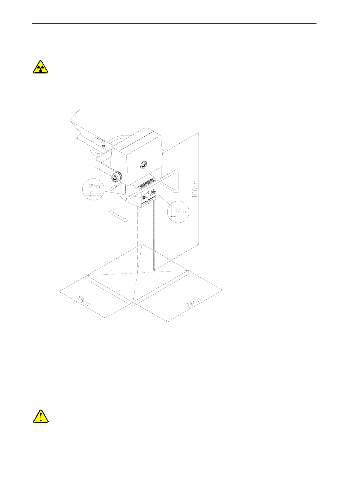
X-ray irradiation field check
Warning: X-ray presence, use proper protections.
This test verifies the correspondence between collimator light and X-ray field.
Place under the collimator, at 1m from the focus, a 18x24 cassette with film.
1.
Press the COLLIMATOR button (both on collimator and keyboard); the lamp will be ON for approx.
2.
30s.
Rotate the handles placed on the collimator and adjust the shutters opening, in order to light the
3.
whole surface of the cassette.
Perform an exposure (i.e. 63kV/10mAs) and check the proper irradiaton of the film (at least within
4.
the requested tolerance).
The X-ray data/parameters vary in function of the cassette type.
As alternative to the cassette it’s possible to use a fluorescent, graduated, high persistence
screen (field position analyzer).
[File: W3006_Rev0.doc] 15 / 19
Page 31

PRACTIX 100 plus Installation & Acceptance
UNIT CONFIGURATION
Default configuration
The unit has been set as follows:
PARAMETER DEFAULT DISPLAY
Maximum kV
(MAX. KV)
Start up kV
(START KV)
Start up mAs
(START mAs)
Language
(LANGUAGE)
APR data storing
(APR mem.)
Starter brake
(SARTER BRAKE)
Dosimeter
(DOSIMETER)
Buzzer
(BUZZER)
Date and time
(DATE-TIME)
125kV 125
63kV 63
4mAs 4
English ENG
disenabled OFF
enabled ON
not present OFF
enabled ON
Rome time zone
(GMT+1.00h)
Customer’s configuration
The user has to be aware of the different working possibilities of the unit, thus to choose the most
convenient and suitable configuration.
Before proceeding it is necessary to fill out, together with the user, the CONFIGURATION SHEET
(see the next page).
[File: W3006_Rev0.doc] 16 / 19
Page 32

PRACTIX 100 plus Installation & Acceptance
Configuration sheet
Unit: PRACTIX 100 plus s/n°:
Place of installation: Date of installation:
Dept: Date of maintenance:
Maximum kV value.
(please, choose between 40 and 125)
kV value at start up.
(please, choose between 40 and the maximum kV value)
……………….kV
……………….kV
mAs value at start up.
……………….mAs
Messages language.
(choose among English, Spanish, French and German)
Availability to store APR values modified by the operator.
Disenablation of the anode braking.
Dosimeter presence.
(available on request)
Disenablation of beeper.
User’s signature: Technician’s signature:
K yes K no
K yes K no
K yes K no
K yes K no
……………….
[File: W3006_Rev0.doc] 17 / 19
Page 33

PRACTIX 100 plus Installation & Acceptance
Configuration
Now it’s possible to set the unit with the values indicated in the CONFIGURATION SHEET. By
SERVICE MODE activate the CONFIG function (see the chapter “Service information”) and modify
the parameters.
Please note that, with the service technician’s intervention, it will be always possible to modify the
configuration parameters.
Date and time setting
Set date and time, follow the DATE-TIME procedure (please refer to SEVICE MODE, described in
the chapter “Service information”).
With the service technician’s intervention, it will be always possible to modify the
configuration parameters.
[File: W3006_Rev0.doc] 18 / 19
Page 34

PRACTIX 100 plus Installation & Acceptance
DOCUMENT STATUS
Rev. Date Page/s Modification description
0 Document approval
1
2
3
4
5
[File: W3006_Rev0.doc] 19 / 19
Page 35

PRACTIX 100 PLUS
REPLACEMENT
[File: W3010_Rev0.doc]
Page 36

PRACTIX 100 plus Replacement
SUMMARY
PROCEDURES DESCRIPTION 1
Electrical parts replacement ................................................................................................................1
Mechanical parts replacement............................................................................................................. 2
Lamp replacement.........................................................................................................................2
Monobloc replacement................................................................................................................... 5
Collimator dismounting .................................................................................................................. 9
PROCEDURES DESCRIPTION
Electrical parts replacement
Should a fault or a malfunctioning be detected, it is advisable to replace the boards (and not to
repair them). The boards provided will be already tested and adjusted.
In case of any adjustment, please refer to the chapter “Adjustments”.
[File: W3010_Rev0.doc] 1 / 12
Page 37

PRACTIX 100 plus Replacement
Mechanical parts replacement
Lamp replacement
WARNING: Before proceeding make sure of the lamp bracket, lamp and socket cooling.
Danger of fingers burning!!.
1. Disconnect the mains.
Block the unit brakes.
Park the arm in the lowered position and activate the safety brake.
2. Remove the filters holder slides (4 screws).
3. Remove the rear cover (2 screws). Pay attention to wires.
Remove the handles (2 hexagonal, ø2mm).
Remove the top of the extractable meter (1 screw).
Disconnect the clamp of the lamp button (2 screws, no polarity) placed on the collimator side.
[File: W3010_Rev0.doc] 2 / 12
Page 38

PRACTIX 100 plus Replacement
4. Remove the front cover (pay attention not to break the extractable meter).
5. Remove the 4 screws of the front cover (2 long, 2 short).
Remove the second front cover (very carefully, this is not an easy operation).
[File: W3010_Rev0.doc] 3 / 12
Page 39

PRACTIX 100 plus Replacement
6. Remove the 2 screws and the spacers of the lamp protection cover.
7.
Do not touch the lamp, socket or lamp bracket with fingers. These could be very hot and
cause severe burns.
EVEN IF COLD, NEVER TOUCH THE LAMP WITH UNPROTECTED HANDS!!
Carefully remove the faulty lamp.
Replace the lamp with a new one type:
PHILIPS PROJECTION LAMP
Type 7023
FCR A1/215
12V 100W GY6.35
cod. 3222 617 51621 or 7222 613 32021
or equivalent
8. Make sure that the lamp pins are completely inserted in the lamp-holder.
9. Follow the foregoing steps from the bottom to re-mount the collimator assembly.
10. Before remounting the handles close both shutters and adjust the handle indicators.
[File: W3010_Rev0.doc] 4 / 12
Page 40

Monobloc replacement
This procedure can cause severe and serious damages to unit and/or operators.
Act VERY CAREFULLY while
How to arrange the unit for the replacement.
1.
Disconnect the unit from the mains.
Block the unit brakes.
Park the arm in horizontal position.
Properly stretch a stout belt or a rope
front leg. Make sure that the rope cannot slide towards the arm pivot. To perform this operation,
tightly bind the rope between the blocking handle for the rotation and the monobloc stirrup.
Furthermore, check that the rope is well stretched.
IMPORTANT: When the monobloc is removed from its support, a force at the arm
extremity directed to the
PRACTIX 100 plus Replacement
performing any operation.
(resisting to 100kgf/1000N at least) between arm and
top, will be present (of approx. 40kgf/400N).
[File: W3010_Rev0.doc] 5 / 12
Page 41

PRACTIX 100 plus Replacement
How to remove the monobloc cover.
2.
Remove the 2 protective cups and loosen the 2 screws placed in the upper part of the monobloc
cover.
Loosen the 4 screws placed in the lower part of the cover.
Remove the 2 covers.
[File: W3010_Rev0.doc] 6 / 12
Page 42

PRACTIX 100 plus Replacement
How to remove the monobloc.
3.
Loosen the 4 lateral screws and remove the monobloc cover support.
Disconnect the supply and signal cables from the monobloc: the connection is performed by tearing
clamps. No tool is required, except for the ground conductor.
ATTENTION: the following step is the most dangerous. The rope will be subjected
to a sudden tension of
stout the arm could arise suddenly, causin
several kgf (>60kgf); if rope and hitches are not properly
g really severe damages for the
operators around and the unit. Before removing the monobloc, it is adv
carefully stretch the rope as much as possible, so that it will be subjected to
fewer stresse
s.
Loosen the 4 nuts with plain and Grower washers which fix the monobloc to the support. This way,
the monobloc is completely free and, acting very carefully, can be removed.
For any reason, DO NOT REMOVE or UN-STRECTH the rope.
In this status the unit might be really dangerou
s, therefore, operate thus to let
the unit as less as possible in such condition.
None, except the tech
nician who will re-mount the monobloc, must approach the
unit.
Do not let the unit unguarded.
isable to
[File: W3010_Rev0.doc] 7 / 12
Page 43

PRACTIX 100 plus Replacement
How to re-mount the monobloc.
4.
Place the monobloc on the support.
Grip the 4 nuts by plain and Grower washers, in order to fix the monobloc to the support and make
sure that these are well gripped.
Connect to the monobloc the supply and signal cables: the connection is performed by tearing
clamps. No tool is required, except for the ground conductor.
Re-mount the monobloc cover support and grip the 4 lateral screws.
How to re-mount the monobloc cover.
5.
Re-mount the 2 covers.
Grip the 4 screws placed in the lower part of the cover.
Grip the 2 screws placed in the upper part of the monobloc cover.
Re-insert the 2 protective cups.
How to arrange the unit to the functioning.
6.
Make sure that the monobloc is well fixed.
Remove the rope ONLY after checking that it is not under tension anymore.
Perform the x-ray tube calibration (see the corresponding par.).
Perform the X-ray beam centering with the rotating adapter (see the corresponding par.).
Check the proper correspondence between X-ray beam and light field of the collimator.
[File: W3010_Rev0.doc] 8 / 12
Page 44

Collimator dismounting
Disconnect the unit from the mains.
1.
Block the unit brakes.
Park the arm in the lowered position and activate the safety brake.
Rotate upwards the monobloc/collimator group.
PRACTIX 100 plus Replacement
Remove the filters holder slides (4 screws).
2.
[File: W3010_Rev0.doc] 9 / 12
Page 45

PRACTIX 100 plus Replacement
Remove the rear cover (2 screws). Pay attention to wires.
3.
Disconnect the cables from the 4 clamps.
4.
Remove the cable clamp (fork wrench ø6mm) and withdraw the cable carefully.
signal cable clamp
lamp order (1) black 1
--2
+V1 (12V DC 9A) (3) brown 3
0V1 (4) blue 4
GND (2) yellow/green GND
[File: W3010_Rev0.doc] 10 / 12
Page 46

Withdraw the cable from the hole on the rear cover.
5.
PRACTIX 100 plus Replacement
6.
If the arm has not been previously blocked it may arise suddenly!!
Loosen the 4 grub-screws in the upper part of the collimator (warning: do not let the collimator fall).
[File: W3010_Rev0.doc] 11 / 12
Page 47

PRACTIX 100 plus Replacement
DOCUMENT STATUS
Rev. Date Page/s Modification description
0 Document approval
1
2
3
4
5
[File: W3010_Rev0.doc] 12 / 12
Page 48

PRACTIX 100 PLUS
ADJUSTMENTS
[File: W3012_Rev0.doc]
Page 49

PRACTIX 100 plus Adjustments
SUMMARY
ELECTRICAL ADJUSTMENTS 2
X-ray tube calibration ......................................................................................................................... 2
Trimmers...........................................................................................................................................2
MECHANICAL ADJUSTMENT 4
Collimator.......................................................................................................................................... 4
Alignment between X-ray beam and rotating adapter....................................................................... 4
Arm balancing adjustment.............................................................................................................. 7
Adjustment of the arm balancing clutch...............................................................................................8
Adjustment of the fork-monobloc clutch............................................................................................... 9
[File: W3012_Rev0.doc] 1/10
Page 50

PRACTIX 100 plus Adjustments
ELECTRICAL ADJUSTMENTS
The most important electrical adjustments are performed by the SERVICE MODE (see the
corresponding chapter). Therefore, it’s possible to modify the operating parameters even if the
unit cover is closed (risks and times are reduced).
The adjustments that require the cover removing are already performed by the manufacturer
during the unit checking and, usually, must not be re-performed.
X-ray tube calibration
See the chapt. “Service information” SERVICE MODE TUBE CALIBRATION option.
Trimmers
Every trimmer is properly set in factory. Regulations can be performed only if strictly
necessary. Un-proper regulations may be dangerous.
(CW= clockwise rotation, CCW= counterclockwise rotation)
Board Trimmer Value Test Point Function
B1
Keyboard
P1 - -
CW Increases the LCD contrast
Board Trimmer Value Test Point Function
B4
Charger
P1 25kHz TP4
P2
P3 6,80V max TP6
P4 6,9V max TP5
6µs
TP4 CCW Increases the Dead Time
CCW Increases the charger converter
working frequency
Sets the capacitors battery voltage
(Vc=680V)
CW Increases V
Reference voltage for capacitors supervisor
circuits.
CW Anticipates the safety circuit
intervention time
Board Trimmer Value Test Point Function
B5
Chopper
Control
P1 20kHz TP5
P2 -7,5V TP2
P3 -5,5V TP3
CW Increases the chopper working
frequency
Sets the Chopper output voltage to 375V.
CW Increases the output voltage.
Sets the Chopper max. output current to
55A.
CCW Decreases the Chopper max output
current
.
C
[File: W3012_Rev0.doc] 2/10
Page 51

PRACTIX 100 plus Adjustments
Board Trimmer Value Test Point Function
B7
Filament
*
ONLY FOR FACTORY TEST
P2*
P3 17kHz TP2
P4*
0÷4V
0÷7V
TP3 FIL DAC OUT simulation trimmer: enabled if
B4-JP2 is in “b-c” position.
CW Increases.
CCW Increases the filament working
frequency
TP1 mA SET signal simulation trimmer: enabled
if B4-JP3 is in “b-c” position (1V=20mA).
CW To increase.
Perform B11 board trimmers regulation with XR ENABLE and XR ORDER signals enabled, but
without high level power. Discharge the capacitors battery (procedure described in the chapter
“Fault finding” ) and remove the inverter feeding fuses B6-F1 and F2.
Board Trimmer Value Test Point Function
B11
Inverter
Control
P1 10,0Vmax TP3 Max output voltage of the error amp. (10V)
P2 16,6kHz IC9-1 Sets the inverter working frequency.
On IC9-1 a symmetrical square wave with
60µs period has to be measured.
P3 6,25Vmax TP4 Sets the max. kV SET voltage
(6,25V=125kV).
P4 25µs IC13-1 Sets the first IGBT “on” time.
The impulse is high active for 25µs.
P5
25µs
IC13-8 Sets the second IGBT “on” time.
The impulse is high active for 25µs.
[File: W3012_Rev0.doc] 3/10
Page 52

PRACTIX 100 plus Adjustments
MECHANICAL ADJUSTMENT
Collimator
Alignment between X-ray beam and rotating adapter
Warning: X-ray presence, use proper protections.
This adjustment has to be performed only in case of monobloc, rotating adapter or handle
replacement.
In order to obtain a proper balancing of X-ray source, anode and variable position of the rotating
adapter, perform the following operations:
1. Turn the unit OFF and park the arm in the lowered position, then upwards rotate the monobloc with
collimator.
2. Remove the collimator (see the corresponding chapter).
3. Mount the centering tool on the rotating adapter.
For this operation, plug the centering tool and rotate it until the 4 holes on the tool are aligned with
the 4 fixing bolts of the rotating adapter.
Unlock the arm and rotate the centering tool downwards.
4.
[File: W3012_Rev0.doc] 4/10
Page 53

PRACTIX 100 plus Adjustments
5. Turn the unit ON and wait for the “READY” signal.
6. Take all the radioprotective precautions, then set 60kV/10mAs and perform an exposure.
7. Expose the film and measure P and Q distances.
When the P and Q distances are lower than 1mm, the collimator is centered on the tube and no readjustment is needed.
[File: W3012_Rev0.doc] 5/10
Page 54

PRACTIX 100 plus Adjustments
8. If, on the basis of the measurement on the film, the rotating adapter is not centered, loosen the four
bolts which fix the rotating adapter to the tube, then move the rotating adapter and repeat
exposures on the film until the tolerance achieved is less than 1mm.
9. Switch the unit OFF.
10. Grip the four bolts which fix the rotating adapter and remove the centering tool.
11. Re-mount the collimator (see the corresponding chapter).
[File: W3012_Rev0.doc] 6/10
Page 55

PRACTIX 100 plus Adjustments
Arm balancing adjustment
The ideal weight balancing must be obtained with the arm in horizontal position.
The spring nut for the arm balancing is accessible from the bottom of the unit.
Its adjustment must be performed with a Ø19mm fix spanner.
The procedure is as follows:
1. Completely loosen the arm balancing clutch (see the following paragraph)
2. Completely arise the arm.
The hexagonal nut of the balancing spring is accessible from the bottom of the central column.
3. With a fixed spanner (Ø19mm) rotate the nut as follows:
• turn counterclockwise in order to increase the balancing compensation (if the arm goes down)
• turn clockwise in order to decrease the balancing compensation (if the arm goes up)
4. Adjust the arm balancing clutch (see the next paragraph)
[File: W3012_Rev0.doc] 7/10
Page 56

PRACTIX 100 plus Adjustments
Adjustment of the arm balancing clutch
The clutch function is to keep the arm in the wished position even if the proper balancing is not
exact.
Usually, the clutch is completely loosened during the weight balancing procedure, and then is
gripped until the arm is balanced in every position (even with the arm completely arose or
lowered) and the movement is perfectly smooth and regular.
To adjust the clutch:
1. Remove the cup that covers the clutch with a small screwdriver acting on the edge.
2. Using the special tool to adjustment the clutch and rotate the rod.
• Rotate counterclockwise to loosen the clutch.
• Rotate clockwise to grip the clutch.
3. Once the adjustment is performed, re-mount the plastic cup.
[File: W3012_Rev0.doc] 8/10
Page 57

PRACTIX 100 plus Adjustments
Adjustment of the fork-monobloc clutch
The clutch adjustment is necessary to obtain a smooth movement and to keep the monobloc in
the wished position.
In case the monobloc does not keep the wished position grip the clutch.
To adjust the clutch:
1. By means of a hexagonal male wrench loosen the 3 grub screws and remove the goniometer.
2. Using the special tool for the clutch adjustment, rotate the rod.
• Rotate counterclockwise to loosen the clutch.
• Rotate clockwise to grip the clutch.
3. Once the adjustment is performed, re-mount the plastic cup.
[File: W3012_Rev0.doc] 9/10
Page 58

PRACTIX 100 plus Adjustments
DOCUMENT STATUS
Rev. Date Page/s Modification description
0 Document approval
1
2
3
4
5
[File: W3012_Rev0.doc] 10/10
Page 59

PRACTIX 100 PLUS
FAULTS FINDING
[File: W3014_Rev0.doc]
Page 60

PRACTIX 100 plus Faults finding
SUMMARY
BOARDS POSITION 2
TROUBLESHOOTING GUIDE 3
Non-displayed faults........................................................................................................................... 3
Displayed faults .................................................................................................................................. 4
DESCRIPTION 8
Signals............................................................................................................................................... 8
Leds................................................................................................................................................ 16
Test point ........................................................................................................................................ 19
Fuses............................................................................................................................................... 22
Jumpers........................................................................................................................................... 23
Relays ............................................................................................................................................. 24
Timing diagrams............................................................................................................................... 25
Chopper IGBT driver.................................................................................................................... 25
Inverter IGBT drivers................................................................................................................... 25
CAPACITORS BATTERY 26
Description....................................................................................................................................... 26
Charging time.............................................................................................................................. 27
Natural discharging time .............................................................................................................. 27
Forced discharging time............................................................................................................... 27
Capacitors discharge procedure.................................................................................................... 28
DO NOT PERFORM HAZARDOUS OPERATIONS
ELECTICAL SHOCK DANGER
Even if the mains plug is disconnected a dangerous voltage can be
present inside the unit, if the capa
citors battery is not completely
discharged.
PERFORM THE DISCHARGE PROCEDURE
Before performing any operation on Capacitors Battery, Power Unit
and on the Inverter power circuits i
capacitors battery.
THE DISCHARGE PROCEDURE IS DESCRIBED AT THE END OF
CHAPTER.
t is necessary to discharge the
THIS
[File: W3014_Rev0.doc] 1/30
Page 61

BOARDS POSITION
&
R
PRACTIX 100 plus Faults finding
B1 - OPERATO
INTERF. BOARD
B9 - RELEASE MODE
SWITCH BOARD
S1 - POWER SUPPLY
(AC-DC)
inverter
IHF2011
B3 - IGNITION
STARTER BOARD
resist. R1
line switch SWL1
mains filter FT1
B7 - FILAMENT BOARD
S2 - POWER SUPPLY
(DC-DC)
B8 - HANDSWITCH
BOARD
B6 - POWER CHOPPER BOARD
B5 - CONTROL
CHOPPER BOARD
B2 - MANAGEMENT
PROCESSOR BOARD
B4 - CHARGER BOARD
cond. elect. C1
capacitors battery
inductor L1
capacitors battery
[File: W3014_Rev0.doc] 2/30
Page 62

PRACTIX 100 plus Faults finding
TROUBLESHOOTING GUIDE
Should a fault or a malfunctioning be detected, it is advisable to replace the boards (and not to
repair them). The boards provided will be already tested and adjusted.
In case of any adjustment, please refer to the chapter “Adjustments”.
Non-displayed faults
Problem Likely causes Remedy Point to Check
Check that the automatic main switch
placed on the right side of the unit is in
“I” position.
It is impossible to
turn the unit ON.
The MAINS signal
(yellow led) near
the ON push
button is OFF.
It is impossible to
perform X-ray.
The READY signal
(green led) on
panel is OFF.
Collimator lamp
doesn’t light up.
The unit is ON but
LCD is OFF.
a) Automatic main switch in “0”
position.
b) Leak of mains voltage.
c) Faulty power supply plug.
d) Faulty S1 power supplier.
In stand-by phase the voltage to
the capacitors battery is lower
than 600V.
Usually a branch of the capacitors
battery has exceeded 350V, the
CHARGER may not be properly
supplied or faulty.
The lamp fuse is burnt or the
lamp filament is interrupted.
a) B2 board (MPB) faulty or not
feeded.
b) B1 board (OIB) or LCD are
faulty.
Ensure the presence of the mains
voltage to the power supply socket.
Ensure that the mains voltage is present
inside the unit, the led Ld1 on B3 board
should be lighting up.
Check the S1-F1 fuse integrity as well as
its output voltage.
Check the B3-F5 fuse integrity, it feeds
the ignition circuit.
Check on B4 Charger board the
following:
- F2 fuse
- +VC FAULT and -VC FAULT signals
- CHARGER ENABLE signal
- DISABLE signal
B3-Ld6 led has to be ON. When OFF the
B3-F6 is faulty.
If the fuse is functioning properly,
replace the halogen lamp in the
collimator.
WARNING. Never handle the lamp glass
bulb with un-protected hands. In case of
accidental contact immediately wash
with water and soap, then dry with a
clean cloth.
Check on B2 board the following:
- the 5Vm voltage presence
- the efficiency of the flat cable CF1
connection between MPB and OIB.
SWL1“I”
B3-Ld1ON
S1-F1
B3-Tp1/Tp2 =13,2V
B3-F5
B4-F2
B4-Ld1OFF
B4-Ld2OFF
B2-Ld27ON
B4-Ld5ON
B4-Ld6ON
B4-Ld7ON
B3-Ld6ON
B3-F6
Collimator lamp.
B2-Tp1/Tp25Vm
B2-CF1
[File: W3014_Rev0.doc] 3/30
Page 63

Displayed faults
PRACTIX 100 plus Faults finding
Message on
Display
HAND SWITCH
ERR
V2 FAULT
CALL SERVICE
V3 FAULT
CALL SERVICE
POWER FAULT
CALL SERVICE
CHOPPER FAULT
Likely causes Remedy Point to Check
Upon the ignition the HS PRE
and/or HS RAD control is already
present.
The Handswitch might be faulty.
Lack of V2 power supply. S2
supplier is faulty, or the
Hardware safety circuit
intervention occurs.
Lack of V3 power supply.
The supplying fuses of the Power
Unit are burst or the S3 power
supplier is faulty.
A) Generated by CHARGER
FAULT (B4-Ld1 or Ld2 ON).
In the Capacitors Battery (CB)
there is an unbalancing between
the positive and negative
branches. Maybe a capacitor is
discharging, faulty, or a fuse
burst. Usually if the capacitor is
faulty, the fuse as a
consequence, burns.
B) CB has not achieved 650V
within approx. 120s from the
ignition.
Usually a capacitors battery
branch has exceeded 350V, or
the CHARGER is not supplied or
faulty.
C) Generated by CHOPPER
FAULT (B5-Ld2 ON).
The Chopper output voltage
exceeded 400V. The IGBT driver
circuit or the IGBT itself could be
faulty.
Chopper device error.
It is generated in preparation
phase if CHOPPER output is lower
than 320V (B5-Ld1 OFF).
Check the Handswitch functioning and
the integrity of its cable.
Ld17 and Ld18 leds, connected to the
MPB inputs, should be OFF without
controlling the Handswitch. If ON
replace the Handswitch.
If mounted, please check the optional IR
REMOTE CONTROL.
Check the fuse of S2 supplier.
Check on B2 board (MPB) the following:
- V2 OK signal
- CPU RUNNING signal.
Check on B3 board (I&S) the following:
- F1 and F2 fuses.
Check on Charger B4 board the
following:
- mains voltage presence,
- 320 VL continuos voltage,
- F1 fuse.
Before operating, make sure
that each capacitor is totally discharged
(see the end of this chapter).
If the voltage to the capacitors leads is
< than 280V, the corresponding green
led is OFF.
Check the integrity of the protection
fuses of every capacitor.
Check on the B4 Charger board the
following:
- F2 fuse
- +VC FAULT and -VC FAULT signals
- CHARGER ENABLE signal
- DISABLE signal
Enable X-ray preparation, and
check on B5 the following:
- CHARGER ENABLE signal
- VSET signal
- VFEED signal
- IGBT DRIVER signal
Check that there is not a short
circuit between Collector and Emitter of
the IGBT mounted on B6 board.
Enable X-ray preparation, and on
B5, check the following:
- CHOPPER ENABLE signal
- VSET signal
- IGBT DRIVER signal
HS PREB2-Ld18
HS RADB2-Ld17
S2-F1
B2-Ld1ON
B2-Ld19ON
B2-Ld4OFF
B3-F1 & F2
B4-Ld10ON
B4-F1
B4-Ld1OFF
B4-Ld2OFF
CB (1/2 left):
Ld1÷6ON
F1÷6
CB (2/2 right):
Ld1÷6ON
F1÷6
B4-F2
B4-Ld1OFF
B4-Ld2OFF
B2-Ld27ON
B4-Ld5ON
B4-Ld6ON
B4-Ld7ON
B2-Ld27ON
B5-Tp2-7,6Vmax
B5-Tp61V=50V
B5-TP12 / TP11
B2-Ld29ON
B5-Tp2-7,6Vmax
B5-TP12 / TP11
[File: W3014_Rev0.doc] 4/30
Page 64

PRACTIX 100 plus Faults finding
Message on
Display
STARTER
INTERLOCK
FILAMENT
CALL SERVICE
LACK OF X-RAY
Likely causes Remedy Point to Check
If during preparation phase the
start-current of the anode is not
sufficient or missing, no STARTER
READY signal is present (B3-Ld5
is OFF)
Min. safety current intervention
(green led B7-Ld2 OFF).
Filament current is absent or
lower than 220mA.
Likely causes:
a) Faulty filament fuse
b) Faulty filament board
c) Faulty DAC circuit on B3
board
d) Discontinued filament
Max. safety current intervention
(red led B7-Ld1ON).
The filament current has
exceeded for a while the
maximum allowed value
(>480mA).
Likely causes:
a) Faulty filament board
b) Faulty DAC circuit on B3
board
The kV value has not reached the
85% of the set value in the first
10ms of exposures, or there is
not high voltage.
Likely causes:
a) The inverter doesn’t send
kV>85% signal.
b) Chopper and Inverter
protective fuses are
discontinuos.
Check the following:
- integrity of B3-F3 and F4 fuses
- efficiency of the connection
between the B3 board and the
stator turns.
- STARTER ENABLE signal
- B3-K3 relay excitation
- STARTER RUN signal
Check on B7 board the
following:
- F1 fuse.
- the integrity of connection between
the board (B7-CM10) and the
filament (B10-CP2).
- ±15V2 supplier
- FIL DAC OUT signal (in standby=2,5V)
- FIL SET signal (in st.by = 3,5V)
- FIL CUR signal (1V=50mA)
- mA SET signal (1V=20mA)
Perform an exposure and
check the KV>85% signal presence on
the boards:
B11-Ld1ON
B2-Ld11ON
If the leds won’t light up discharge the
capacitors battery and check the B6-F1
and B6-F2 extra fast fuses integrity.
B3-F3 & F4
B3-CM3/CM4
B2-Ld22
B3-K3
B2-Ld20
B7-F1
B7-Tp5, Tp9, TP4
B7-Tp3
B7-Tp7
B7-Tp8
B7-Tp1
B11-Ld1
B2-Ld11
B6-F1 & F2
INVERTER KV
ERROR
a) High voltage circuit in the Xray assembly is unbalanced or kV
feed-back is not present during
an exposure or it is out of range.
The red led B11-Ld3 is on.
b) During X-ray emission the kV
decrease under 85%. The
Inverter missing the kV>85%
(during emission B11-Ld1 turns
OFF).
c) During X-ray emission the kV
increase over 110% of set value
(software control on TUBE KV
analog signal).
[File: W3014_Rev0.doc] 5/30
Perform an exposure and check on
the Inverter B11 board the following:
- KV FEED signal (1V = 20kV)
- the KV+ and kV- signals balancing
- kV>85% signal
- TUBE KV signal (1V = 20kV)
B11-Tp1
B11-Tp5 e Tp6
B11-Ld1ON
B2-Tp6
Page 65

PRACTIX 100 plus Faults finding
Message on
Display
INVERTER
OVERLOAD
INVERTER FAULT
MAX TIME
DATA ERR.
CALL SERVICE
ERR. TUBE CALIB.
CALL SERVICE
TUBE SEASONING
Likely causes Remedy Point to Check
Inverter current absorption is too
high (Ipk>300A).
Red led B11-Ld4 lights up.
Monobloc fault or too high
anodical current.
IGBT drivers error.
B11-Ld5 red led lights up.
The max exposure time (2s) has
been achieved.
XR ORDER circuit (X-ray order is
always ON) or the filament
control one (anodic mA too low)
might be faulty.
Checksum data error, memory
error. The EEPROM memory B2IC21 is faulty.
Data in the memory are out of
range. These could be wrong or
the EEPROM B2-IC21 faulty.
After a long period of un-use (3
months or more) it’s necessary to
perform the X-ray tube
seasoning, in order to avoid any
damage.
in preparation phase check on B7
board the following signals:
- FIL DAC OUT
- mA SET
- FIL CUR
in radiography phase
- ANODIC mA
- mA STABILIZATION
Perform an exposure. Replace the
Inverter if the fault persists.
Check that the B2-Ld24 led (XR ORDER
signal) is ON only during the X-ray time.
Check the anodic mA value; if umproper, check the following on B7 board:
- FIL DAC OUT signal
- mA SET signal
- FIL CUR signal
- mA STABILIZATION signal
Replace the B2-IC21 IC.
Perform the tube calibration, if the error
persists please replace B2-IC21 IC.
Perform the tube seasoning.
B7-Tp3
B7-Tp1 (1V=20mA)
B7-Tp8 (1V=100mA)
B11-Tp8 (1V=20mA)
B2-Ld26
B2-Ld24OFF
B11-Tp8 (1V=20mA)
B7-Tp3
B7-Tp1 (1V=20mA)
B7-Tp8 (1V=100mA)
B2-Ld26
[File: W3014_Rev0.doc] 6/30
Page 66

PRACTIX 100 plus Faults finding
Message on
Display
INACTIVE
Dosimeter
NOT OK
Likely causes Remedy Point to Check
The dosimeter chamber is active
but MPB does not recognize it.
The chamber is active but the
feedback pulses are out of range.
Check the following:
- the connection efficiency between
MPB board and DOSIMETER
- the 15Vd supply presence
- the TEST SIGNAL presence (B2-
Ld32 high active for 1s) at start-up.
Check the efficiency of the connection
between MPB board and DOSIMETER.
S2-7/8
B2-Ld32
215 < PULS > 275
[File: W3014_Rev0.doc] 7/30
Page 67

PRACTIX 100 plus Faults finding
DESCRIPTION
Signals
Power supplies signals
Mnemonic Signal description Path
MAIN SUPPLY
+V1
+12V1
± 15V2
Vd
Vm
VL
115V±10% mains voltage or 230V±10%, 50/60Hz. It is
connected to the ac/dc S1 power supplier and, through the
B3-K1 relay, to the Power Unit. The voltage presence is
indicated by the green led B3-Ld1.
The S1 power supplier generates the +V1 power supply
(13Vdc), it is present even if the unit is OFF. It supplies the
insertion circuit, the collimator and dc/dc S2 power
supplier. If voltage is present, the green led placed on the
keyboard near the “on” key, lights up.
This voltage is referred to GND.
The +V1 voltage supplies the B3-Q1-E transistor. Upon the
unit ignition, the Q1-C transistor transfers the +12V1=
(+V1- Vcesat) voltage to the starter checking circuits.
Furthermore, it supplies the Handswitch and the Infrared
Handswitch optional accessory.
The V2 power supply (±15Vdc) is generated by the S2
power supplier and is present upon the unit turning ON.
This voltage supplies the Hardware safety circuits and if no
fault is present, through the B2-K2 relay, also the Filament
and Inverter checking circuits and some in/out circuit on
MPB are supplied.
+15Vd power supply for dosimeter; generated by S2 and
not referred to GND.
+5Vm power supply for CPU; generated by S2 and not
referred to GND.
Rectified and filtrated mains voltage for the (320Vdc)
Charger and Filament power supply.
Its presence is indicated by the green led B4-Ld10.
ATTENTION! Circuits are not isolated from the mains,
(LIVE) danger of severe electrical shock.
Plug Filter B3 B4
S1 B3 Collimator
S1 B3
S2 B2
S2 B2 Dosimeter
S2 B5
Line B3 B4 B7
Ignition signals
Mnemonic Signal description Path
ON
OFF
S2 ENABLE
LINE 115
ON control by keyboard.
OFF control by keyboard.
Enabling signal for S2 power supplier. It is present with
the unit in “on” status.
It indicates to MPB if the unit is supplied at 230V or at
115V, in order to fix the start time and brake time of the
rotating anode.
Vrete=230V B3-Ld2=ON time=0,8s
Vrete=115V B3-Ld2=OFF time=1,6s
Trip point=150V
[File: W3014_Rev0.doc] 8/30
B1 B3
B1 B3
B3 S2
B3 B5
Page 68

PRACTIX 100 plus Faults finding
Hardware safety signals
Mnemonic Signal description Path
V2 OK
CPU RUNNING
MAX XR TIME
High active signal. In case of unbalancing between the V2
pos. and neg. the signal is missing, the red led B2-Ld2
lights up and the “V2 FAULT CALL SERVICE” alarm is
displayed. For safety reasons, the B2-K1/K2 relays are
disexcited, taking off the V1voltage to the X-ray key, ±V2
power supply to Inverter and Filament and the V3 to the
Charger/Chopper control signals. To reset the safety
status, turn the unit OFF.
High active signal. If the program blocks the signal is
missing and the red led B2-Ld4 lights up. For safety
reasons, the B2-K1/K2 relays are unexcited, taking off the
V1voltage to the X-ray key, ±V2 power supply to Inverter
and Filament and the V3 to the Charger/Chopper control
signals. To reset the safety status, turn the unit OFF.
Low active signal. In case the exposure time is > 2,1s (Red
led B2-Ld3 ON), the hardware safety blocks the unit
functioning. For safety reasons, the B2-K1/K2 relays are
unexcited, taking off the V1 voltage to X-ray key, ±V2
power supply to Inverter and Filament and V3 to the
Charger/Chopper control signals. To reset the safety
status, turn the unit OFF.
B2
B2
B2
X-ray control signals
Mnemonic Signal description Path
HS COM
HS PRE
HS RAD
THERMAL SAFETY
REALISE MODE
SWITCH
Handswitch +12V1power supply. It is selected by the
hardware safety circuit through the B2-K2 relay.
X-ray preparation request of the “dead man” type.
(Yellow led B2-Ld18 ON).
X-ray request of the “dead man” type. (Yellow led B2-Ld17
ON).
It is active with the medium temperature > 57°C of the
monobloc (Yellow led B2-Ld6 OFF).
Its intervention let the eventual current exposure complete,
then the “HOT TUBE” message is displayed and any other
X-ray request is blocked, until the monobloc returns to a
lower temperature.
Slide switch at two positions that allows the selection of the
X-ray request; Handswitch or Infrared remote control.
The mounting in series of the Infrared remote control is
not foreseen.
HS B8 B3-B2
HS B8 B3-B2
HS B8 B3-B2
B3 Monob B3 B2
B9
[File: W3014_Rev0.doc] 9/30
Page 69

PRACTIX 100 plus Faults finding
Charger signals
Mnemonic Signal description Path
V3
Vc
+VC
-VC
V3 OK
CHARGER ENABLE
CHARGER FAULT
BAT DISC
VBAT
RES
DISABLE
CHARGER OFF
STOP
±15V3 power supply for the Chopper and Charger checking
circuits. Voltages presence is indicated by the green led B4Ld9 (+) and B4-Ld8 (-). This voltage is referred to GND.
Voltage to the capacitor battery leads (±350Vc); the 0Vc is
connected to GND.
ATTENTION! If capacitors haven’t been discharged this
voltage is present even if the unit is OFF and unplugged.
The natural discharge requires approx.3h. the capacitor
charging status is indicated by the green led B4-Ld3
(branch +) and B4-Ld4 (branch -), that light up to 35V
voltage per each branch. It’s possible to discharge the
battery instantaneously operating by the keyboard
(SERVICE MODE DIAGNOSTIC menu CAPACITORS
option) or pressing the red button B4-PB1 for a while.
ATTENTION! Before operating on the Power Unit verify, by
means of a Voltmeter, that every capacitor is completely
discharged. Do not perform risky operations. Dangers of
severe electrical shock even if the unit is OFF.
Voltages feedback of the capacitors battery positive and
negative branches. They are also used in the unbalancing
circuit and voltage max safety. The unbalancing is
indicated by the red leds B4-Ld1(+) and B4-Ld2 (-).
It is generated by the ±15V3 supply voltage supervisor. In
case the V3 power supplier is faulty, the green led B4-Ld11
is OFF and the “V3 FAULT CALL SERVICE” alarm is
displayed.
Capacitors charge enable signal. It is generated by MPB
upon the “start up test” end, and disappears during X-ray.
High active when the voltage of a capacitor battery branch
is higher then 350Vc. If it is active the capacitor charge is
blocked via hardware and “POWER FAULT CALL SERVICE”
is displayed.
For safety reasons, the Chopper Fault signal trigs the
capacitors battery discharge.
The discharge can be also activated by keyboard in
SERVICE MODE DIAGNOSTIC menu CAPACITORS
option. The lighting up of the red led B4-Ld12 indicates the
discharging circuit trig.
Analogic signal for the battery voltage measurement in
1/100 format in the 0-7V range. It is converted into
frequency on MPB (1V2kHz), to indicate the battery
voltage.
Initial active low reset. It is generated upon the ignition
and blocks the battery charge for approx.500ms.
When high active it blocks the converter for the battery
charge. The yellow led B4-Ld5 is OFF.
Generated when the capacitor battery reaches the
requested charging value. (±340Vc). Its typical hysteresis is
of 5Vc. The signal is low active.
Safety signal generated by a chopper fault condition or a
battery discharge. The signal is active and permanent. To
deactivate it, turn the unit OFF and ON again.
B4
B4 Cap.Bat B5
B4
B4 B2
B2 B4
B4 B2
B2 B4
B4 B2
B4
B4
B4
B4
[File: W3014_Rev0.doc] 10/30
Page 70

PRACTIX 100 plus Faults finding
Charger signals
Mnemonic Signal description Path
+VC FAULT
-VC FAULT
SCR ON
High active safety signals. The capacitor charge is blocked
when the voltage of a battery branch is more than 350V.
(the checking circuit of the charge could be faulty or an
unbalancing between the positive and negative branches of
the battery has happened). The intervention is indicated by
red leds B4-Ld1(+) or B4-Ld2 (-) and the “POWER FAULT”
alarm is displayed. To reset the block, turn the unit OFF
and ON again.
Safety signal. It is active if the discharging thyristor B4-TH2
is “on”, in this status the battery is blocked. The charge is
automatically enabled when TH2 returns in “off” status.
B4
B4
Control Chopper & Chopper signals
Mnemonic Signal description Path
V3
±15V mains voltage for the Charger and Chopper checking
circuits. This voltage is referred to GND.
B4 B5
Va
CHOPPER ENABLE
CHOPPER READY
CHOPPER FAULT
ISET
VSET
EN
IEA
VEA
SEA
FAULT
±13V mains voltage for the IGBT driver.
It is generated from a dc/dc of +15V3.
ATTENTION! this voltage is NOT referred to ground but
connected to Vc. Danger of electrical shock.
This signal is generated by MBP for the Chopper
enablation. In stand-by status the chopper output voltage
is kept at 320Vdc max. During preparation, or X-ray, it
reaches 380Vdc max.
This signal is high active when the chopper output voltage
is more than 320V. To allow X-rays the signal must be
active.
High active high signal. If, and anytime, the Chopper
output voltage is >400V, the signal is generated, blocking
the Chopper and Charger functioning. For safety reasons,
the capacitor battery discharge is automatically trigged.
The ”POWER FAULT CALL SERVICE” alarm is displayed.
Setting of the max. output current from the Chopper in
1V10A (B5-TP3) format. Typical value: 50A.
Setting of the max output voltage from the Chopper in
1V50V (B5-TP2) format. Typical value: 370V.
In case of high signal, the error amplifier outputs and the
PWM circuit output are activated.
Output signal of the current error amplifier.
Output signal of the voltage error amplifier.
Sum signal of the error amplifiers. If the signal is at low
level, the Chopper power transistor is interdicted.
Equal to the “Chopper fault” signal, but low active. It
blocks the transfer of the PWM signal to the IGBT Driver.
B5
B2 B4 B5
B5 B4 B2
B5 B4 B2
B5
B5
B5
B5
B5
B5
B5
[File: W3014_Rev0.doc] 11/30
Page 71

PRACTIX 100 plus Faults finding
Starter signals
Mnemonic Signal description Path
STARTER ENABLE
STARTER RUN
STARTER BRAKE
STARTER READY
PRINC
SHIFT
COM
Safety signal generated by high active MPB. It controls the
B3-K3 relay, that selects the TH1/TH2 Triac and the mains
stator.
The relay is controlled so that its contacts always close and
open in “zero power” status, therefore with “off” Triacs.
Generated by the high active MPB that, by means of TH1
and TH2 Triac, let the rotating anode stator run.
The start time is fixed by the mains voltage and controlled
by MPB: 230V0,8sec; 115V1,6sec.
Generated by high active MPB guiding the TH2 Triac.TH2
supplies only in half wave the stator main wrapping, aimed
to block the anode during the rotation.
The brake time is fixed by the mains voltage and controlled
by MPB 230V0,8sec; 115V1,6sec.
Braking can be disenabled in set up phase.
(SERVICE MODE SETUP menu Brake OFF).
High active signal (B3-Ld5 ON), present during the
whole starting phase, if currents flowing in the stator are
higher than the pre-fixed minimum. If currents do not
exceed the minimum fixed, the “STARTER INTERLOOK”
alarm is displayed.
Principal winding (R=20Ω).
ATTENTION! Danger of electrical shock, mains voltage.
Shift winding (R=50Ω).
ATTENTION! Danger of electrical shock, mains voltage.
Common windings.
ATTENTION! Danger of electrical shock, mains voltage.
B2 B3
B2 B3
B2 B3
B3 B2
B3 Monobloc
B3 Monobloc
B3 Monobloc
[File: W3014_Rev0.doc] 12/30
Page 72

Label Signal description Path
VL
FIL DAC OUT
FIL SET
FIL CUR
mA SET
ANODIC mA
mA STABILIZATION
FILAMENT READY
PRACTIX 100 plus Faults finding
Filament signals
Rectified and filtrated mains voltage (320Vdc) to supply the
filament and its power circuit (half bridge). The fuse B7-F1
of 1A selects it. Attention! Mains voltage circuits. Danger
of electrical shock.
Voltage generated by MPB for the filament ignition. In
stand by its value is +2V. In preparation, it is in function of
the kV and mAs set parameters and can reach +4V.
Control voltage for the filament ignition with the
1V100mA format. Its value is determined by the FIL DAC
OUT voltage added to 1V.
[ V FIL SET = V FIL DAC OUT + 1 ]
Voltage proportional to the filament current with 1V50mA
format. Its max filament current is of approx. 480mA.
Voltage generated by MBP comprised between +3,7V at
+7,0V. It is sent to the automatic adjustment circuit of the
anodic current, as reference voltage. Its value is in function
of the set kV and mAs parameters; the correspondence is
1V20mA.
Voltage generated by the tube anodic current; the
correspondence is 1V20mA, between 0 and 7V. This
signal is sent to the filament, as feedback, for the mA
adjustment and to MPB for the mAs counting, therefore it
determines the exposure block.
High active signal generated by MPB. It enables the circuit
of the automatic adjustment for the anodic current. For
safety reasons it is cut from the Handswitch and is active
only during X-ray.
This signal is high active (B7-Ld2 ON) if the filament
current is comprised between 220mA and 480mA. A
current out of range blocks the unit functioning and the
“FILAMENT CALL SERVICE” alarm is displayed. If the alarm
has been generated by a current > than 480mA the red led
B7-Ld1 lights up and stores the intervention of the max.
current safety. This safety intervention excites the B7-K1
relay, cutting the filament, to protect it from over-current.
To reset the safety status, turn the unit OFF.
Line B3 B4 B7
B2 B7
B2 B7
B2
B2 B7
Monob B11 B2
B7
B2 B7
B7 B2
[File: W3014_Rev0.doc] 13/30
Page 73

PRACTIX 100 plus Faults finding
Inverter signals
Mnemonic Signal description Path
kV SET
XR ENABLE
XR ORDER
kV>85%
TUBE kV
KV/20
ANODIC mA
kV FAULT
OVERLOAD
IGBT FAULT
RESET FAULT
Voltage generated by MPB for the kV setting to the X-ray
tube. The format is kV/20 and the range from 2 to 6,25V
High active signal for the inverter enablation (Yellow led
B2-Ld23ON). The signal is cut by the Handswitch and by
the hardware safety circuits.
High active signal for x-ray control (Yellow led B2Ld2ON). It also trigs the MAX XR TIME timer for the
hardware safety. (2,1s) For safety reasons it is cut by the
Handswitch and by the hardware safety circuits. To obtain
X-ray, the inverter has to be enabled.
High active signal. Generated by the inverter when the
High Voltage is more than the 85% of the set kV value.
(Yellow led B11-Ld1ON). This signal enables the mAs
counting start.
Voltage proportional to the High Voltage applied to the
tube; the correspondence is 1V20kV. It is sent to the
MPB for the kV measurement in SERVICE MODE.
Voltage proportional to the High Voltage applied to the
tube; the correspondence is 1V20kV. This signal is used
for the electrical kV measurement and is connected to the
kV adjustment circuits as comparison voltage.
Voltage generated by the tube anodic current; the
correspondence is 1V20mA. This signal is sent to the
filament as feed back for the mA adjustment and to MPB
for the mAs counting, therefore it determines the exposure
time.
High active fault signal that blocks the exposure (Red led
B11-Ld3ON). It is generated by the inverter in case of
unbalancing on High Voltage or lack of feedback. Usually it
is caused by a fault in the monobloc (Tube, diodes,
coils...). The INVERTER kV ERR” alarm is displayed.
High active fault signal. It is generated when the current
value absorbed by the monobloc is too high; the inverter
functioning and X-ray are blocked. (Red led B11-Ld40n).
This can happen in case of: High Voltage in the monobloc,
too high anodic mA value (usually in the tube calibration
phase), or a monobloc fault. (Tube, diodes, coils...).
The ”INVERTER OVERLOAD” alarm is displayed.
High active fault signal (Red led B11-Ld5ON). It is
generated when in the Inverter IGBT drivers occurs an
unsafe control or a functioning defect. The “INVERTER
FAULT” alarm is displayed.
High active signal. It is a pulse of approx. 20ms generated
by the MPB upon the anode starting phase ending. It is
necessary to reset an eventual inverter fault happened in
the foregoing exposure. (B2-Ld25ON).
B2 B11
B2 B11
B2 B11
B11 B2
B11 B2
B11
Monob B11 B2
B7
B11 B2
B11 B2
B11 B2
B2 B11
[File: W3014_Rev0.doc] 14/30
Page 74

PRACTIX 100 plus Faults finding
Collimator signals
Mnemonic Signal description Path
+V1
LAMP REQUEST
LAMP ORDER
Mains voltage. (13Vdc-8A) The green led B3-Ld6 indicates
the voltage presence and the fuse integrity B3-F6 of 10A.
Request of collimator lamp turning ON, by keyboard or
Infrared Remote Control.
Low active signal. It trigs the timer for the lamp turning
ON. Once the timer has been trigged, the lamp lights up
for approx. 30s.
S1 B3 Collimator
B1 B3
B3 Collimator
Dosimeter signals
Dosimeter is not provided in standard configuration. To activate it, during installation phase, it is
necessary to get access to the SERVICE MODE and to the CONFIG menu.
Mnemonic Signal description Path
Vd
TEST SIGNAL
15V voltage for the dosimeter power supply. This voltage
generated by the S2 power supply is electrically divided by
the othes and is not referred to GND.
5s, after the unit ignition the signal is generated by the
MPB and sent to the dosimeter. (Yellow led B2-Ld32ON).
The pulse duration is 1s long, high active. Following the
TEST SIGNAL the dosimeter sends a series of pulses. For a
proper functioning, the response pulses must be comprised
between 215 and 275. Three different cases are foreseen:
1) Return pulses are in the range; the display shows on
the first line ”Dosimeter ACTIV”.
2) Return pulses are out of range; the display shows
“Dosimeter NOT OK”.
3) No return pulse is read; the display shows “Dosimeter
INACTIV”.
The message on the display is cancelled after approx.5s. If
the first case has occurred, the first line shows ”cGYcm2”.
S2 B2 Collimator
Dosimeter
B2 Collimator
Dosimeter
PULS SIGNAL
With X-rays the dosimeter generates pulses in current. The
quantity is proportional to the dose that flows in the
dosimeter in 1 pulse0,1cGy cm² format.
The pulse width (with current) is of approx. 1,5µs for a
max. of 300.000 pulses per second.
Following the TEST SIGNAL the dosimeter responds with a
series of pulses. For the proper functioning the pulses must
be comprised between 215 and 275.
Upon the unit ignition to a max. of 5s, the dosimeter can
generate casual pulses; these have to be disregarded.
Dosimeter Collimator
B2
[File: W3014_Rev0.doc] 15/30
Page 75

Leds
PRACTIX 100 plus Faults finding
Green led = G
In the normal functioning they have to be ON.
One G led in OFF status indicates a faulty condition or busy.
Usually it indicates the presence of a power supply.
Yellow led = Y Indicting a function activity.
Red led = R In the normal functioning they have to be OFF.
One R led in ON status indicates an anomaly or a faulty status.
Board Led Color Function with led on
B1
Key-board
Ld1÷3 G
Ld4÷6 Y
Ld7 Y
The unit is in ready status, therefore enabled to operate.
X-ray emission signal.
V1 voltage presence and integrity of the B3-F5 fuse for
the insertion circuits power supply.
Board Led Color Function with led ON
B2
MPB
Ld1 G
Ld2 R
Ld3 R
Ld4 R
Ld5 Y
Ld6 G
Ld7 Y
Ld8 R
Ld9 R
Ld10 R
Ld11 Y
Ld12 G
Ld13 G
Ld14 R
Ld15 Y
Ld16 R
Ld17 Y
Ld18 Y
Ld19 G
Ld20 Y
Ld21 Y
Ld22 Y
Ld23 Y
Ld24 Y
Ld25 Y
Ld26 Y
Safety signal not present; No fault detected.
Voltage V2 KO, faulty.
Max XR Time. Exposure time > than 2,1s.
CPU Running. Um-proper or absent program flow.
IN “Starter Ready” - Sufficient anodical current.
Enabled only in start time.
IN “Thermal Safety” - ON when the monobloc
temperature is proper to operate (<57°C)
IN “Line 115” - ON with main line voltage = 230V
IN “IGBT Fault” - Faulty Inverter.
IN “Over-current” - Over-loaded inverter.
IN “kV Fault” - Faulty Inverter or monobloc.
IN “kV>85%” - ON when kV are > 85% of set value.
IN “Filament Ready” - Filament current in range.
IN “V3 OK”- Voltage V3 OK
IN “Charger Fault” - The voltage of the capacitors
battery is wrong
IN “Chopper Ready” - ON if chopper output voltage is
> than 320V.
IN “Chopper Fault” - The Chopper output was > than
400V for a time longer than 5ms.
IN “HS RAD” - X-ray emission request by Handswitch.
IN “HS PRE” - X-ray preparation by Handswitch.
IN “V2 OK” - Voltage V2 OK
OUT “Starter Run” - ON in the anode start time phase.
OUT “Starter Brake” - ON in the anode braking phase.
OUT “Starter Enable” - ON in start time or when is
breaking.
OUT “XR Enable” - ON to enable the inverter.
OUT “XR Order” - ON with X-ray control.
OUT “Reset Fault” - ON for 20ms at the end of anode
start time.
OUT “mA Stabilization” - ON in correspondence of the
X-ray exposure.
(> 350V or unbalanced).
[File: W3014_Rev0.doc] 16/30
Page 76

PRACTIX 100 plus Faults finding
Board Led Color Function with led ON
B2
MPB
Ld27 Y
Ld28 R
Ld29 Y
Ld30 Y
Ld31 Y
Ld32 Y
OUT “Charger Enable”
OUT “Bat Disc” - ON when the battery discharge is
controlled by the keyboard. (SERVICE MODE).
OUT “Chopper Enable”
OUT - In normal condition the led pulses with f = 4Hz
OUT “Autocal” - Always ON, when OFF it performs the
V/f converters auto-calibration.
OUT “Test Dos” - After 5s from the ignition it is active
for 1s and enables the dosimeter test.
Board Led Color Function with led ON
B3
on/off
starter
collimator
Ld1 G
Ld2 Y
Ld3 Y
Ld4 Y
Ld5 Y
Ld6 G
Mains voltage presence.
Mains voltage = 230V
The starter capacitive current is ready.
The starter main current is ready.
Starter Ready. The starter currents are ready. Enabled
only during start time
V1 voltage is OK and fuse B3-F6 is OK (collimator feeding
voltage).
.
Board Led Color Function with led ON
B4
Charger
Ld1 R
Ld2 R
Ld3 G
Ld4 G
Ld5 Y
Ld6-Ld7 Y
Ld8 G
Ld9 G
Ld10 G
Ld11 G
Ld12 R
Battery positive branch > than 350V.
Battery negative branch > than 350V.
Monitor of the battery positive voltage.
Monitor of the battery negative voltage.
ON to enable the battery charge.
Converter and charger driver monitors. ON when the unit
is charging.
Voltage -15V3 OK
Voltage +15V3 OK
Voltage 320V OK and fuses B3-F1 & F2 are Ok.
V3 OK - Voltage V3 OK and fuse B4-F1 is Ok.
Battery discharge circuit (crowbar) driver enables.
Board Led Color Function with led ON
B5
Control Chopper
Ld1 Y
Ld2 R
Chopper Ready - ON if the chopper output voltage is >
than 320V.
Chopper Fault - The chopper output was > than 400V
for a time longer than 5ms.
Board Led Color Function with led ON
B7
Filament
Ld1 R
Ld2 G
The filament current was > than 480mA for a time longer
than 120 ms.
Filament ready - Filament current in the range.
[File: W3014_Rev0.doc] 17/30
Page 77

PRACTIX 100 plus Faults finding
Board Led Color Function with led ON
B11
Inverter
Ld1 Y
Ld2 R
Ld3 R
Ld4 R
Ld5 R
kV>85% - is ON when kV value is > than 85% of set
value.
Not used.
kV Fault - Faulty Inverter or monobloc.
Overload - Overloaded Inverter.
IGBT Fault - Faulty Inverter.
Board Led Color Function with led ON
Capacitors
Battery
Ld1÷6 G
Show capacitors charge and capacitors fuses state.
WARNING: electrical shock danger. Before any operation
make sure, by means of a voltmeter, that capacitors are
completely discharged.
[File: W3014_Rev0.doc] 18/30
Page 78

Test point
PRACTIX 100 plus Faults finding
OIB
B1 description ref. to
Tp1 +5Vm supply TP2 +5V
Tp2 0Vm supply floating --- --- ---
right
value
range
±0,3V
format
1V=↓↓
---
MPB
B2 description ref. to
Tp1 +5Vm supply TP2 +5V
Tp2 0Vm supply floating --- --- --Tp3 Output DAC of filament current set Tp18 2,5Vst.by
Tp4 Input ADC of filament current (FIL CUR) Tp18 9,6Vmax 0÷9,6V 50mA
Tp5 Output DAC of mA SET Tp18 7Vmax 1,9÷7V 20mA
Tp6 Input ADC of monobloc voltage(TUBE kV) Tp18 6,3Vmax
Tp7 Output DAC of kV SET Tp18 6,3Vmax
Tp8 Voltage reference for ADC & DAC Tp18 2,048V --- ---
Tp9 Input V/f converter of ANODIC mA Tp20 7Vmax
Tp10 Output V/f converter of ANODIC mA TP2 --- 0÷14kHz 2kHz
Tp11 Input V/f converter of VC (cap.bat voltage) Tp20 6,8Vmax 0÷7V 100V
Tp12 Out V/f converter of VC (cap.bat voltage) TP2 --Tp13 Voltage reference for V/f converter TP2 8,2V --- --Tp14 XR-ORDER signal TP2 +15V --- --Tp15 There is not
Tp16 Converters supply after solid state fuse F1 Tp18 +15V ±0,5V --Tp17 Supply after regulator VR1 Tp18 +5V ±0,3V --Tp18 Converters supply GND 0V --- --Tp19 +15V2 analog and converters supply Tp20 +15V ±0,5V --Tp20 0V2 analog and converters supply GND 0V --- --Tp21 -15V2 analog and converters supply Tp21 -15V ±0,5V ---
right
value
range
±0,3V
2÷4V
0÷6,3V
2÷6,3V
0÷7V
0÷14kHz
format
1V=↓↓
---
---
20kV
20mA
20mA
2kHz
I&S
B3 description ref. to
Tp1 0V1 supply GND 0V --- ---
Tp2 V1 supply Tp1 13,2V
Tp3 Capacitors current signal (starter). Tp1 5,8V*
Tp4 Voltage reference for comparators of starter
currents.
Tp5 Virtual ground for AC amplifier IC1(LM324) Tp1 6V ±0,5 --Tp6 Main current signal (starter). TP1 5,8V*
Tp7 0V1 supply GND 0V --- ---
* in stand by status
** in preparation
[File: W3014_Rev0.doc] 19/30
Tp1 7,9V ±0,3 ---
right
value
range
±0,2
9,4÷10VpK**
9,4÷10VpK**
format
1V=↓↓
---
---
---
Page 79

PRACTIX 100 plus Faults finding
CHARGER
B4 description ref. to
Tp1 +15V3 supply Tp2 +15V
Tp2 0V3 supply GND 0V --- --Tp3 -15V3 supply Tp2 -15V
Tp4 Charger converter clock Tp2 25kHz ± 200Hz --Tp5 Voltage reference safety circuit Tp2 6,9V --- 100V
Tp6
Tp7
Tp8
(VC/100)
Capacitors battery voltage / 100
(-Vc/50)
Negative battery branch / 50
(+Vc/50)
Positive battery branch / 50
Tp2 6,8V
Tp2 -6,8V
Tp2 6,8V 0÷6,8V 50V
right
value
range
±0,5V
±0,5V
0÷6,8V
0÷(-6,8)V
format
1V=↓↓
---
---
100V
50V
CHOPPER CONTROL
B5 description ref. to
Tp1 0V3 supply GND 0V --- --Tp2 set Vout (370V) Tp9 -7,5V --- 50V
Tp3 set Iout Max (55A) Tp9 -5,5V --- 10A
Tp4
Tp5 PWM clock for Chopper regulation Tp9 20kHz --- ---
Tp6 Chopper voltage feedback Tp9 7,5Vmax 0÷7,5V 50A
Tp7 +15V3 supply Tp9 +15V
Tp8 Chopper current feedback Tp9 5,5Vmax 0÷5,5V 10A
Tp9 0V3 supply GND 0V --- ---
Tp10 -15V3 supply Tp9 -15V ±0,5V --Tp13 0V3 supply GND 0V --- ---
Tp11
Tp12
Error amplifier output signal (High=IGBT max
conduction)
DANGER 700V REFERRED TO GND
0Va supply for IGBT drive
IGBT drive signal
Tp9 ---
floating 0Va --- ---
Tp11 --- ±13,5V ---
right
value
range
0÷15V
±0,5V
format
1V=↓↓
---
---
[File: W3014_Rev0.doc] 20/30
Page 80

PRACTIX 100 plus Faults finding
FILAMENT
B7 description ref. to
Tp1 Output DAC of mA SET Tp9 7Vmax
Tp2 Clock for Filament PWM regulation Tp9 16kHz --- --Tp3 Output DAC of filament current set Tp9 2,5Vst.by
Tp4 -15V2 supply Tp9 -15V ±0,5V --Tp5 +15V2 supply Tp9 +15V ±0,5V --Tp6 Input of ANODIC mA (feedback) Tp9 7Vmax
Tp7 Filament current set Tp9 3,5Vst.by
Tp8 Filament current feedback Tp9 7Vst.by 0÷10V 50mA f
Tp9 0V2 supply GND 0V --- ---
Tp10 0V2 supply GND 0V --- --a= anodic
f= filament
right
value
range
1,9÷7V
2÷4V
0÷7V
0÷5V
format
1V=↓↓
20mA a
---
20mA a
100mA f
INVETER CONTROL
B11 description ref. to
Tp1 Tube kV (feedback signal) Tp10 6,25Vmax 0÷6,25V 20kV
Tp2 kV set Tp10 6,25Vmax 2÷6,25V 20kV
Tp3 Error amplifier clamp Tp10 10V
Tp4 kV set clamp Tp10 6,25V --- --Tp5 kV- feedback Tp10 6,25Vmax
Tp6 kV+ feedback Tp10 6,25Vmax
Tp8 Input of ANODIC mA (feedback) Tp10 7Vmax 0÷7V 20mA
Tp9 +15V2 supply Tp10 +15V ±0,5V --Tp10 0V2 supply GND 0V --- --Tp11 -15V2 supply Tp10 -15V ±0,5V ---
right
value
range
0÷10V
0÷6,25V
0÷6,25V
format
1V=↓↓
---
10kV
10kV
[File: W3014_Rev0.doc] 21/30
Page 81

PRACTIX 100 plus Faults finding
Fuses
Even if the mains plug is disconnected there may be dangerous voltage into the unit, if the
capacitors battery is not discharged.
DO NOT PERFORM HAZARDOUS OPERATIONS
ELECTRIC SHOCK DANGER
Board Fuse Value Function
S1
Power Supply
+V1
F1
Board Fuse Value Function
S2
Power Supply
±±V2, Vm, Vd
F1
3,15A -T Power supplier input protection (mains voltage).
10A -T Power supplier input protection (12V1).
Board Fuse Value Function
B3
on/off
starter
collimator
F1÷F2
F3÷F4
F5
F6
4A - T
4A - T Starter protection (mains voltage).
500mA - T Ignition circuit protection (12V1).
10A - T Collimator protection (12V1).
B3 board output / charger supply protection (mains
voltage).
Board Fuse Value Function
B4
Charger
±±V3 Supply
F1
F2
250mA - T 15V3 supplier input protection (mains voltage).
4A - T Charger inverter circuit protection (320VL).
Board Fuse Value Function
Capacitors
Battery
F1÷F6
20A
Extra Fast
Capacitors protection (one fuse for every capacitor)
(Vc).
Board Fuse Value Function
B6
Chopper
F1÷F2
63A
Extra Fast
Chopper output protection.
Board Fuse Value Function
B7
Filament
F1
1A - T Filament board input protection (320VL.).
[File: W3014_Rev0.doc] 22/30
Page 82

PRACTIX 100 plus Faults finding
Jumpers
During the standard working phase every Jumper (JP) has to be set in “a-c” position.
The “b-c” position is devoted to the options enablation, or to make the faults finding easier.
Charger
Label Description with “b-c” position
B4-JP1 It is possible to check +15V3 supply without load.
B4-JP2 It is possible to check -15V3 supply without load.
B4-Jp3 It limits capacitors battery load to 400V instead of 680V.
Filament
Label Description with “b-c” position
B7-Jp1 Only for test. Aimed to check the relation between the filament current and anodic
current. It allows the exposure without the automatic correction of the anodic
current.
B7-Jp2 Only for test. It allows the manual set of filament current by B7-P2 trimmer.
WARNING. Set the current according to the tube emission curves. DO NOT PERFORM
EXPOSURE IF B7-TP3 VOLTAGE IS NOT COMPRISED BETWEEN 3V AND 3,5V!
B7-Jp3 Only for test. It allows the manual setting of the anodic current through B7-P4
trimmer.
WARNING. Set the current value according to the tube loading curves; 1V measured
in B7-Tp1 corresponds to 20 anodic mA (Max 7V=140mA).
HS BOARD
Label Description with “b-c” position
B8-Jp1 It enables the manual selection between Handswitch and IR Remote Control. If IR
Remote Control option is not available set this jumper in “a-c” position.
[File: W3014_Rev0.doc] 23/30
Page 83

PRACTIX 100 plus Faults finding
Relays
Board Relay Function
B2
MPB
K1
K2
K3
K4
Board Relay Function
B3
On/off
Starter
Collimator
K1
K2
K3
K4
It is driven by the hardware safety circuit (V2 OK, CPU RUNNING, MAX XR
TIME). A contact (12V1) breaks the supply to the Handswitch and to the
Starter controls, the other contact (+15V3) breaks the supply to the
Charger controls.
It is in parallel connected to K1 relay, breaking the inverter and the
filament supply (15V2).
It is excited by the X-ray preparation request (HS PRE). Its contact breaks
the STARTER RUN signal.
It is excited by the exposure request (HS RAD), while unexcited with a
100ms delay. Its contacts break XR ENABLE, XR ORDER, mA
STABILIZATION signals.
Mains supply relay. Controlled by the ignition circuit.
This relay is excited when mains voltage is 230V. It changes the gain of
the reading circuit of the anode stator currents.
It is excited by the STARTER ENABLE signal. It’s excited in run time and
brake time conditions of the anode. It’s driven so that its contacts close
and open when B4-TH1 and TH2 triacs are OFF (zero power switch).
It is excited by the LAMP REQUEST button or by infrared Handswitch. It
generates the LAMP ORDER signal.
Board Relay Function
B7
Filament
K1
K2
Usually it is excited to supply the filament, while unexcited when the
filament current is higher than the max. allowed value.
It is excited during X-ray emission by mA STABILIZATION signal.
[File: W3014_Rev0.doc] 24/30
Page 84

Timing diagrams
Chopper IGBT driver
PRACTIX 100 plus Faults finding
Inverter IGBT drivers
Maximum work frequency
[File: W3014_Rev0.doc] 25/30
Page 85

PRACTIX 100 plus Faults finding
CAPACITORS BATTERY
Description
(refer to electrical drawings)
The capacitors battery is composed by 12 capacitors (17.000µF - 350V) in serial-parallel connected
to supply a ±340V GND referred voltage (680V voltage to battery leads). The battery is divided
into 2 smaller groups, each one of 6 capacitors in serial-parallel connected.
Every capacitor is protected by an extra-fast fuse, in order to break the current in case of short
circuit of a battery element. The charging status of every capacitor is monitored by a green led
(Ld1÷Ld6) in parallel connected; the led is ON only if the capacitor voltage is > 280Vdc, otherwise
it will be OFF.
Green leds B4-Ld3 and B4-Ld4 indicate the voltage present to the capacitor leads of the whole
battery, until a minimum voltage of +35V for the positive branch, and of -35V for the negative
one. When leds are OFF the battery voltage is comprised between 70V and 0V.
The pressure of the red button PB1 placed on the B4 board trigs the forced discharge of the
battery on the R1 high power resistor (80Ω - 150W). It’s possible to trig this operation also if the
unit is OFF, by only if the battery voltage is > 55V. More details are listed here below:
Vbat
(V)
70 +35 -35 well visible
60 +30 -30 less visible
56 +28 -28
45 +23 -23 non sure
40 +20 -20
It’s also possible to trig the capacitor discharge by keyboard, in SERVICE MODE DIAGNOSTIC
menu CAPACITORS option.
+Vc
(V)
If the capacitors battery is not completely discharged, even though the mains plug is
disconnected, a dangerous voltage inside the unit might be present.
-Vc
(V)
Luminosity
B4-Ld3 (+Vc) e B4-Ld4 (-Vc)
OFF
Capacitors
discharge trig
sure
interdicted
[File: W3014_Rev0.doc] 26/30
Page 86

PRACTIX 100 plus Faults finding
Charging time
Capacitors battery charging times are the following:
With 230V or 115V mains
From 0V to 680V ~80s
From 300V to 680V ~45s
Natural discharging time
By the unit turning OFF the batteries naturally discharge in high impedance circuits. In this case
approx. 3 hours are needed.
time [h] voltage [Vdc]
0 680
¼ 430
½ 340
¾ 200
1 130
1½ 55
235
2½ 25
Forced discharging time
By the forced discharge times decrease at approx. 30s.
from to time
230Vdc 5s
680Vdc
Before operating on capacitors make sure, by a voltmeter, that voltage to their
leads is lower than 15
Never directly short-circuit the capacitors poles. The residual voltage and high
capacity may releas
100Vdc 10s
25Vdc 15s
0Vdc 30s
V.
e very dangerous currents.
[File: W3014_Rev0.doc] 27/30
Page 87

Capacitors discharge procedure
a
t
NEVER PERFORM HAZARDOUS OPERATIONS.
ELECTROSHOCK DANGER.
If the capacitors battery is not completely di
plug is disconnected, a dangerous voltage inside the unit might be present.
Before removing the Plexig
Capacitors Battery, Power Unit, Inverter Power Circu
forced discharge.
To ensure that each capacitor battery is discharged (V<15) per
measurement by means of a voltmeter.
For the battery discharge 2 different procedures are foreseen:
1.
In SERVICE MODE DIAGNOSTIC menu CAPACITORS option (see the chapt. “Service
information”). The capacitors battery voltage is shown on display.
OR:
By the pressure of the PB1 red led placed on the B4 board inside the unit. The discharge can be
performed in any moment even with the unit OFF, but only if the battery voltage is > 55V. To get
access to the button remove the 6 screws placed aside and remove the cover.
PRACTIX 100 plus Faults finding
scharged, even though the m
las protection and/or performing any operation on
its and Monobloc trig
form a vol
Warning: from now on, parts under voltage are accessible!!!
[File: W3014_Rev0.doc] 28/30
Page 88

PRACTIX 100 plus Faults finding
By the use of a tool that guarantees a proper isolation (i.e. an isolated screwdriver or a plastic pen)
2.
press the red button for the discharge, through the hole located aside the Plexiglas protection.
ABSOLUTELY AVOID accidental contacts on the board components.
Before removing the Plexiglas protection:
3.
1. Wait until the Ld3 and Ld4 leds are completely OFF (V<70), if needed decrease the
environmental luminosity.
2. Wait for 1min. more.
3. Then, by the means of a voltmeter and through the holes placed in front of the Plexiglas
protection, measure the voltage between poles (+) and GND as well as GND and (-). The
battery is totally discharged only when, in all cases, voltage is <15V.
Never directly short-circuit the capacitors poles. The residual voltage and
high capacity may release
very dangerous currents.
[File: W3014_Rev0.doc] 29/30
Page 89

PRACTIX 100 plus Faults finding
DOCUMENT STATUS
Rev. Date Page/s Modification description
0 Document approval
1
2
3
4
5
[File: W3014_Rev0.doc] 30/30
Page 90

PRACTIX 100 PLUS
SERVICE INFORMATION
[File: W3016_Rev0.doc]
Page 91

PRACTIX 100 plus Service information
SUMMARY
SERVICE INFORMATION CHECKLIST 3
SERVICE TOOLS 5
Required tools and measuring devices for Repairing & Maintenance ......................................................5
Mechanical.................................................................................................................................... 5
Electrical....................................................................................................................................... 5
Radiological................................................................................................................................... 5
Electrical safety ............................................................................................................................. 5
Special tools....................................................................................................................................... 5
KEYBOARD DESCRIPTION 6
Buttons.............................................................................................................................................. 6
Luminous signals................................................................................................................................ 7
Acoustic signals.................................................................................................................................. 7
IGNITION AND START UP 8
NORMAL FUNCTIONING 10
Operative Procedure......................................................................................................................... 10
Notes............................................................................................................................................... 11
SERVICE MODE 12
What is the SERVICE MODE?............................................................................................................. 12
Activation/deactivation of the SERVICE MODE.................................................................................... 12
Main Menu....................................................................................................................................... 12
Menu reference guide....................................................................................................................... 13
menu SETUP: unit setting................................................................................................................. 14
CONFIG: data management of unit configuration........................................................................... 15
DATE-TIME: unit watch setting..................................................................................................... 17
TUBE CALIBRATION..................................................................................................................... 18
TUBE SEASONING ....................................................................................................................... 24
menu DIAGNOSTIC: diagnostic tests ................................................................................................. 27
TEST KV-mA: voltage test, filament and anodic current.................................................................. 27
CAPACITORS: capacitors battery test............................................................................................ 29
FILAMENT: filament ignition and safety test.................................................................................. 30
CHOPPER-STARTER: chopper and starter test ............................................................................... 31
menu ALARM: alarm display.............................................................................................................. 32
Alarm type .................................................................................................................................. 33
For the Unit Operator................................................................................................................... 33
Stored alarms reading.................................................................................................................. 34
Display of the stored alarms......................................................................................................... 34
Reference alarms tables............................................................................................................... 35
Warnings and error messages ...................................................................................................... 38
menu INIT.APR: APR initialization...................................................................................................... 41
APR programs and default parameters.......................................................................................... 41
ACCESORIES AND OPTIONALS 43
DAPmeter........................................................................................................................................ 43
How to install the device.............................................................................................................. 43
What’s different with the DAPmeter installation?............................................................................ 44
Functioning Test.......................................................................................................................... 44
Connections and segnals.............................................................................................................. 45
FAQ 46
DOCUMENT STATUS 47
[File: W3016_Rev0.doc] Rev. 0 - Pag. 1/47
Page 92

PRACTIX 100 plus Service information
[File: W3016_Rev0.doc] Rev. 0 - Pag. 2/47
Page 93

PRACTIX 100 plus Service information
SERVICE INFORMATION CHECKLIST
The following two tables are useful for Service, so that all the information about the technical
interventions during the life time of the unit can be recorded.
Unit: Practix 100 plus Type Nr.:
Date of installation: S/N:
N-Sheet Nr.
Service-
Information Nr.
Implemented
Remark
Date Signature
[File: W3016_Rev0.doc] Rev. 0 - Pag. 3/47
Page 94

PRACTIX 100 plus Service information
N-Sheet Nr.
Service-
Information Nr.
Implemented
Remark
Date Signature
[File: W3016_Rev0.doc] Rev. 0 - Pag. 4/47
Page 95

PRACTIX 100 plus Service information
SERVICE TOOLS
Required tools and measuring devices for Repairing &
Maintenance
Mechanical
Metric standard tools (screwdrivers, etc…)
Electrical
Digital Multimeter .................................................type Fluke 87 or equivalent
Digital storage oscilloscope....................................type Philips PM 3365A or equivalent
Radiological
mAsmeter ............................................................type Philips PM 2618/32 or equivalent
Not invasive kV and Time meter.............................type RTI MINI-X plus or equivalent
Electrical safety
Leakage current meter..........................................type Bender 1000ST or equivalent
Protective ground wire tester.................................type Bender 1000ST or equivalent
Special tools
tool description TX code 12NC
Collimator centering tool. --- 4522-980-31521
Key for the arm and
monobloc clutches
adjustment.
52662 4512-590-23961
[File: W3016_Rev0.doc] Rev. 0 - Pag. 5/47
Page 96

PRACTIX 100 plus Service information
KEYBOARD DESCRIPTION
Here follows a general view of the unit keyboard.
Buttons
Here follows a short description of the buttons function, in normal use, and the signals meaning.
While operating, remember that in SERVICE MODE (SM) some buttons have different functions
according to the use, therefore operate carefully!
ON
OFF Unit OFF
COLLIMATOR
MENU
kV+ kV- Possibility to modify the kV value
mAs+ mAs- Possibility to modify the mAs value
Unit on, the yellow led indicates that the unit is
connected to the mains and supplied
Collimator lamp lighting up
(timed for about 30s)
It allows the pages shifting in menu composed by
several pages
RESET Return to the upper menu
Functions key: F1, F2, F3, F4
F#
They often refer to the nr. of the display line. (4 lines
display)
[File: W3016_Rev0.doc] Rev. 0 - Pag. 6/47
Page 97

PRACTIX 100 plus Service information
Luminous signals
Here follows the list of the luminous signals present on the unit:
POWER
READY ON anytime that the unit is ready for radiography.
X-RAY The lighting up of the led indicates X-ray emission.
It is not possible to disenable the luminous signals.
The yellow led placed aside the ON key indicates that the unit is
connected to the mains and supplied.
Acoustic signals
Here below the list of the most important acoustic signals:
2 BEEP Memorization performed
3 BEEP X-ray emission OK
1 BEEP LONG Alarm, bad-functioning
It is possible to disenable the acoustic signals. (see the next pages).
[File: W3016_Rev0.doc] Rev. 0 - Pag. 7/47
Page 98

PRACTIX 100 plus Service information
IGNITION AND START UP
The Start up is the phase between the unit turning ON and the “READY” message. In this phase
diagnostic and functioning tests are performed, and the capacitors battery is charged.
To turn the unit ON, proceed as follows:
1. make sure that unit is connected to the mains and that the magneto-thermic switch is ON (ON
position);
2. make sure that yellow led placed aside the POWER button is ON, this means that the unit is
properly supplied;
3. press the POWER button;
4. start up sequence description:
4.1. display check: every digit is completely ON (all the pixels are dark);
4.2. leds and beeper check: all the leds on the keyboard turn on and the beeper emits a long
sound;
4.3. software version:
• without dosimeter
PRACTIX 100 PLUS
VER 1.00. 0A
>>>>>>>>>>>>>>>>>>
• with dosimeter
DOSIMETER xxxxx
PRACTIX 100 PLUS
VER 1.00. 0A
>>>>>>>>>>>>>>>>>>
xxxxx: can be ACTIVE, INACTIVE, NOT OK
4.4. battery charging phase: the capacitors are charged and the unit is ready to perform X-ray
th
when the 4
line bar shows 18 “>” symbols; the number of the “>” symbols is
proportional to the capacitors voltage. Every “>” is equivalent to about 35V (i.e.: “>>>>”
is equivalent to 140V).
[File: W3016_Rev0.doc] Rev. 0 - Pag. 8/47
Page 99

PRACTIX 100 plus Service information
5. After the Start up phase the display shows the “READY” message and the READY led is on. If
faults are detected the display will show one of these error messages:
Display Meaning How to proceed
CONFIG.
HAND SWITCH ERR Faulty x-ray hand switch Try again, if error persists call service
ERR. TUBE CALIB.
CALL SERVICE
TUBE SEASONING
CLOCK OFF Clock system fault Press RESET and continue
RESET APR APR checksum fault Press RESET and continue
POWER FAULT
CALL SERVICE
Wrong unit configuration or not
performed
Tube calibration error Call service
After a long period of un-use (3 months
or more) it’s necessary to perform the
setting-in of the X-ray tube, in order to
avoid any damage
Charger and chopper circuits fault
Energy not available
Call service
Press RESET and continue, call service for
tube setting-in
Switch OFF, wait for some minutes, switch
ON, if the error re-appears call service
F
FR
FR
WR
WW-
FR
F = fatal error
W = warning
R = this message is stored in memory (menu ALARM)
English (GB)
CONFIG. CONFIG. CONFIG. CONFIG.
HAND SWITCH ERR HANDSCHALT. DEF BOUTON DEFECT FALLO MANDO
ERR.TUBE CALIB. RÖHRE KALIBRIEREN CALIB. DEFECT. FALLO CALIB.
TUBE SEASONING RÖHRE EINFAHREN FORM. DU TUBE ADJUSTE DEL TUBO
CLOCK OFF TAKTGEBER DEFEKT CHRONO DEF. FALLO RELOJ
RESET APR APR-DATEN DEFEKT INI. APR INI. APR
POWER FAULT STROMVERSORG.DEF BAT. DEFECT. FALLO ACUMUL.
German (D) French (F)
Spanish (E)
[File: W3016_Rev0.doc] Rev. 0 - Pag. 9/47
Page 100

PRACTIX 100 plus Service information
NORMAL FUNCTIONING
This part of the manual briefly describes the operations to be performed in the normal unit use.
Since it contains useful information for the assistance, it is advisable to read it completely.
Operative Procedure
IGNITION
MANUAL MODE
READY
MANUAL
63 4
Adjust the radiological parameters by
pressing kV +/- and mAs +/- buttons
PRESS THE X-RAY BUTTON
TO PERFORM THE EXPOSURE
Press the MENU
button
PROGRAMMED ANATOMIC MODE (APR)
SKULL & TRUNK
UPPER EXTREMITIES
LOWER EXTREMITIES
PEDIATRICS
The display shows 4 exams groups. Each group contains 8 different exams
Press the F# button to select a group
(i.e. F4 to select PAEDIATRICS)
PROGRAMS LIST
Infant Lung 0.5kg
Infant Lung 1.0kg
Infant Lung 1.5kg
Infant Lung 2.0kg
Press the MENU button to shift the menu pages (1and 2)
Press the F# button to select a
program (i.e. F3)
Press the RESET
button
Press the RESET
Press the F2
button
button
Press the
RESET button
The modification of some
radiological parameters towards the
stored values is indicated by the (*)
symbol aside the program name
(line 3)
To store new values it is
necessary to press the F3
and MENU buttons
simultaneously
PROGRAM DISPLAY
READY
PEDIATRICS
Infant Lung 1.5kg
60 0.4
1st line: reserved to messages / 2nd line: selected group
3rd line: program name / 4th line: radiological parameters (kV and mAs)
PRESS THE X-RAY BUTTON TO
PERFORM THE EXPOSURE
[File: W3016_Rev0.doc] Rev. 0 - Pag. 10/47
 Loading...