

Philips PMEG2005AEL Technical data

查询PMEG2005AEL供应商
PMEG2005AEL
0.5 A ultra low VF MEGA Schottky barrier rectifier in leadless
ultra small SOD882 package
Rev. 02 — 27 April 2004 Product data sheet
1. Product profile
1.1 General description
Planar Maximum Efficiency General Application (MEGA) Schottky barrier diode with an
integrated guard ring for stress protection encapsulated in a SOD882 leadless ultra small
plastic package.
1.2 Features
■ Forward current: 0.5 A
■ Reverse voltage: 20 V
■ Ultra low forward voltage
■ Leadless ultra small plastic package
■ Power dissipation comparable to SOT23.
1.3 Applications
■ Ultra high-speed switching
■ Voltage clamping
■ Protection circuits
■ Low voltage rectification
■ High efficiency DC-to-DC conversion
■ Low power consumption applications.
1.4 Quick reference data
Table 1: Quick reference data
Symbol Parameter Value Unit
I
F
V
R
forward current 0.5 A
reverse voltage 20 V
Philips Semiconductors
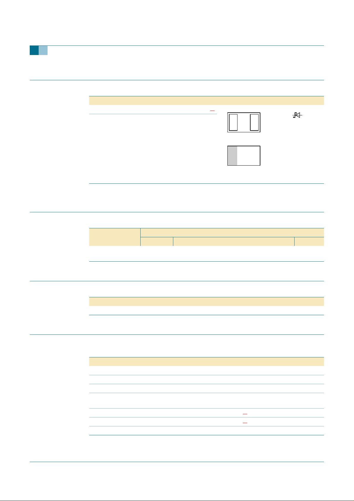
2. Pinning information
Table 2: Discrete pinning
Pin Description Simplified outline Symbol
1 cathode
2 anode
[1] The marking bar indicates the cathode.
3. Ordering information
PMEG2005AEL
0.5 A ultra low VF MEGA Schottky rectifier
[1]
12
21
sym001
Bottom view
Top view
001aaa332
Table 3: Ordering information
Type number Package
PMEG2005AEL - leadless ultra small plastic package; 2 terminals;
4. Marking
Table 4: Marking
Type number Marking code
PMEG2005AEL F2
5. Limiting values
Table 5: Limiting values
In accordance with the Absolute Maximum Rating System (IEC 60134).
Symbol Parameter Conditions Min Max Unit
V
R
I
F
I
FRM
I
FSM
T
j
T
amb
T
stg
Name Description Version
SOD882
body 1.0 × 0.6 × 0.5 mm
continuous reverse voltage - 20 V
continuous forward current - 0.5 A
repetitive peak forward current tp≤ 1 ms; δ≤0.25 - 2.5 A
non-repetitive peak forward
current
junction temperature
operating ambient temperature
t = 8 ms square
wave
-3A
[1]
- 150 °C
[1]
−65 +150 °C
storage temperature −65 +150 °C
9397 750 13201 © Koninklijke Philips Electronics N.V. 2004. All rights reserved.
Product data sheet Rev. 02 — 27 April 2004 2 of 8

Philips Semiconductors
[1] For Schottky barrier diodes thermal run-away has to be considered, as in some applications the reverse
power losses PR are a significant part of the total power losses. Nomograms for determining the reverse
power losses PR and I
6. Thermal characteristics
Table 6: Thermal characteristics
Symbol Parameter Conditions Value Unit
R
th(j-a)
thermal resistance from junction to
ambient
[1] Refer to SOD882 standard mounting conditions (footprint), FR4 with 60 µm copper strip line.
[2] For Schottky barrier diodes thermal run-away has to be considered, as in some applications the reverse
power losses PR are a significant part of the total power losses. Nomograms for determining the reverse
power losses PR and I
7. Characteristics
Table 7: Characteristics
T
=25°C unless otherwise specified
amb
Symbol Parameter Conditions Typ Max Unit
V
F
I
R
C
d
continuous forward
voltage
continuous reverse
current
diode capacitance VR= 1 V; f = 1 MHz;
rating will be available on request.
F(AV)
rating will be available on request.
F(AV)
see Figure 1;
= 0.1 mA 25 60 mV
I
F
= 1 mA 75 110 mV
I
F
= 10 mA 135 190 mV
I
F
= 100 mA 220 290 mV
I
F
= 500 mA 375 440 mV
I
F
see Figure 2;
VR= 10 V 210 600 µA
= 20 V 370 1500 µA
V
R
see
Figure 3
PMEG2005AEL
0.5 A ultra low VF MEGA Schottky rectifier
in free air
[1] [2]
500 K/W
[1]
19 25 pF
[1] Pulse test: tp≤ 300 µs; δ≤0.02.
9397 750 13201 © Koninklijke Philips Electronics N.V. 2004. All rights reserved.
Product data sheet Rev. 02 — 27 April 2004 3 of 8
 Loading...