

Page 1

1. Product profile
1.1 General description
High-voltage, high-speed planar-passivated, NPN power switching tra nsistor in a full pack
plastic package for use in high frequency electronic lighting ballast applications
1.2 Features and benefits
PHE13005X
Silicon diffused power transistor
Rev. 02 — 20 November 2009 Product data sheet
Fast switching
High voltage capability of 700 V
Isolated package
Low thermal resistance
1.3 Applications
Electronic lighting ballasts
1.4 Quick reference data
Table 1. Quick reference
Symbol Parameter Conditions Min Typ Max Unit
I
C
P
tot
V
CESM
Static characteristics
h
FE
collector current DC; see Figure 3, 1 and 2 --4A
total power
dissipation
collector-emitter
peak voltage
DC current gain IC=1A; VCE=5V;
Th≤ 25 °C; see Figure 4 --26W
VBE= 0 V - - 700 V
12 20 40
T
=25°C; see Figure 11
h
=5V; IC=2A;
V
CE
Th=25°C; see Figure 11
10 17 28
Page 2

NXP Semiconductors
sym123
2. Pinning information
PHE13005X
Silicon diffused power transistor
Table 2. Pinning information
Pin Symbol Description Simplified outline Graphic symbol
1B base
2 C collector
3 E emitter
mb
B
mb n.c. isolated
321
SOT186A
(TO-220F)
3. Ordering information
Table 3. Ordering information
Type number Package
PHE13005X TO-220F plastic single-ended package; isolated heatsink mounted; 1 mounting
Name Description Version
hole; 3-lead TO-220 "full pack"
C
E
SOT186A
PHE13005X_2 © NXP B.V. 2009. All rights reserved.
Product data sheet Rev. 02 — 20 November 2009 2 of 13
Page 3
NXP Semiconductors
001aab999
4. Limiting values
PHE13005X
Silicon diffused power transistor
Table 4. Limiting values
In accordance with the Absolute Maximum Rating System (IEC 60134).
Symbol Parameter Conditions Min Max Unit
V
V
V
I
I
I
I
P
T
T
C
CM
B
BM
CESM
CBO
CEO
tot
stg
j
collector-emitter peak
voltage
collector-base voltage IE=0A - 700 V
collector-emitter
voltage
collector current DC; see Figure 3, 1 and 2 -4A
peak collector current - 8 A
base current -2A
peak base current - 4 A
total power dissipation Th≤ 25 °C; see Figure 4 -26W
storage temperature -65 150 °C
junction temperature - 150 °C
8
I
C
(A)
6
VBE=0V - 700 V
IB=0A - 400 V
001aaf009
V
CC
VBE = −5V
4
2
0
0 800600200 400
V
CL(CE)
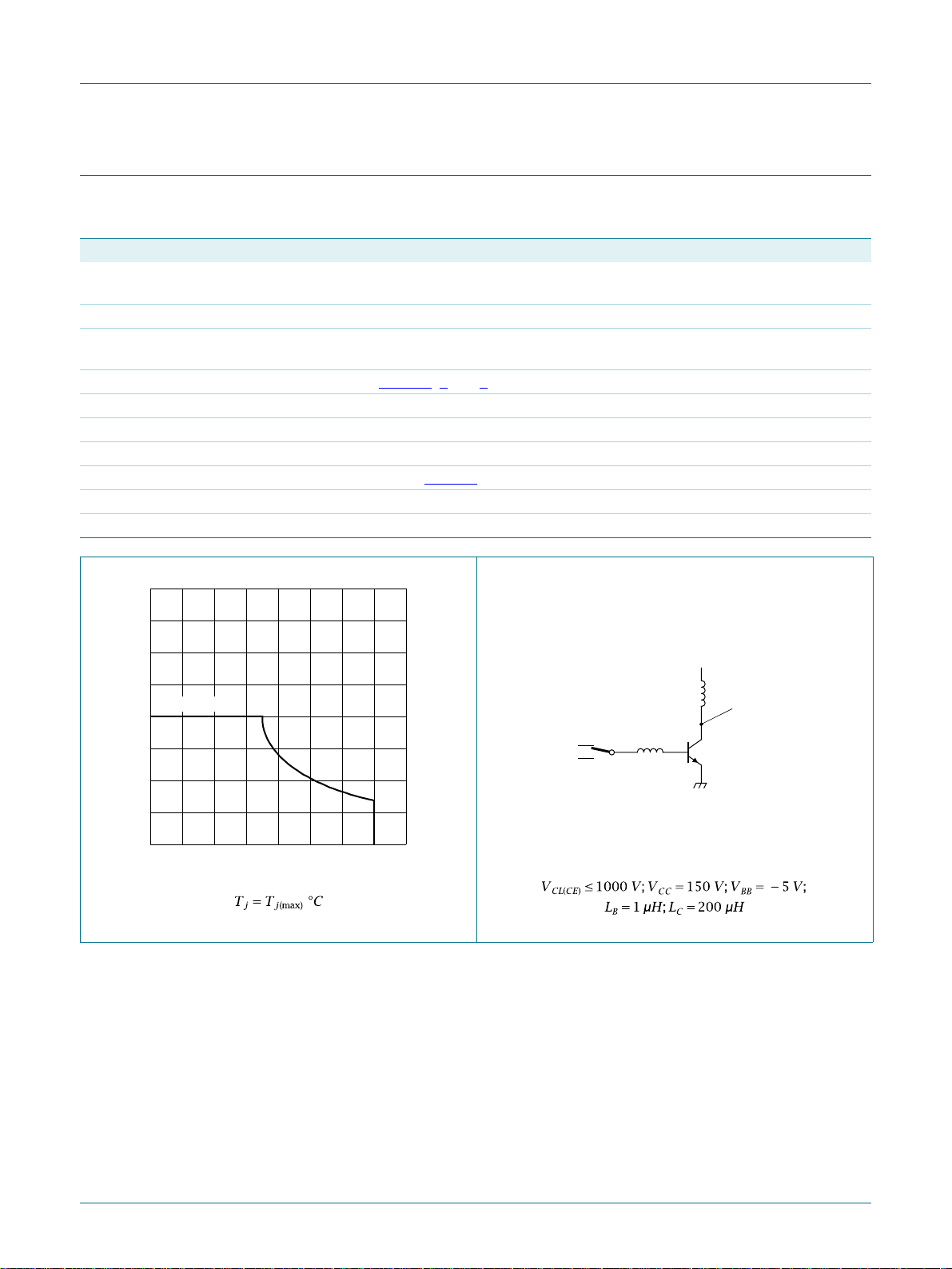
Fig 1. Reverse bias safe operating area
(V)
L
C
V
CL(CE)
probe point
L
I
V
Bon
BB
B
DUT
Fig 2. Test circuit for reverse bias safe operating area
PHE13005X_2 © NXP B.V. 2009. All rights reserved.
Product data sheet Rev. 02 — 20 November 2009 3 of 13
Page 4
NXP Semiconductors
PHE13005X
Silicon diffused power transistor
2
10
I
C
(A)
10
I
CM(max)
I
C(max)
1
−1
10
−2
10
−3
10
1 10
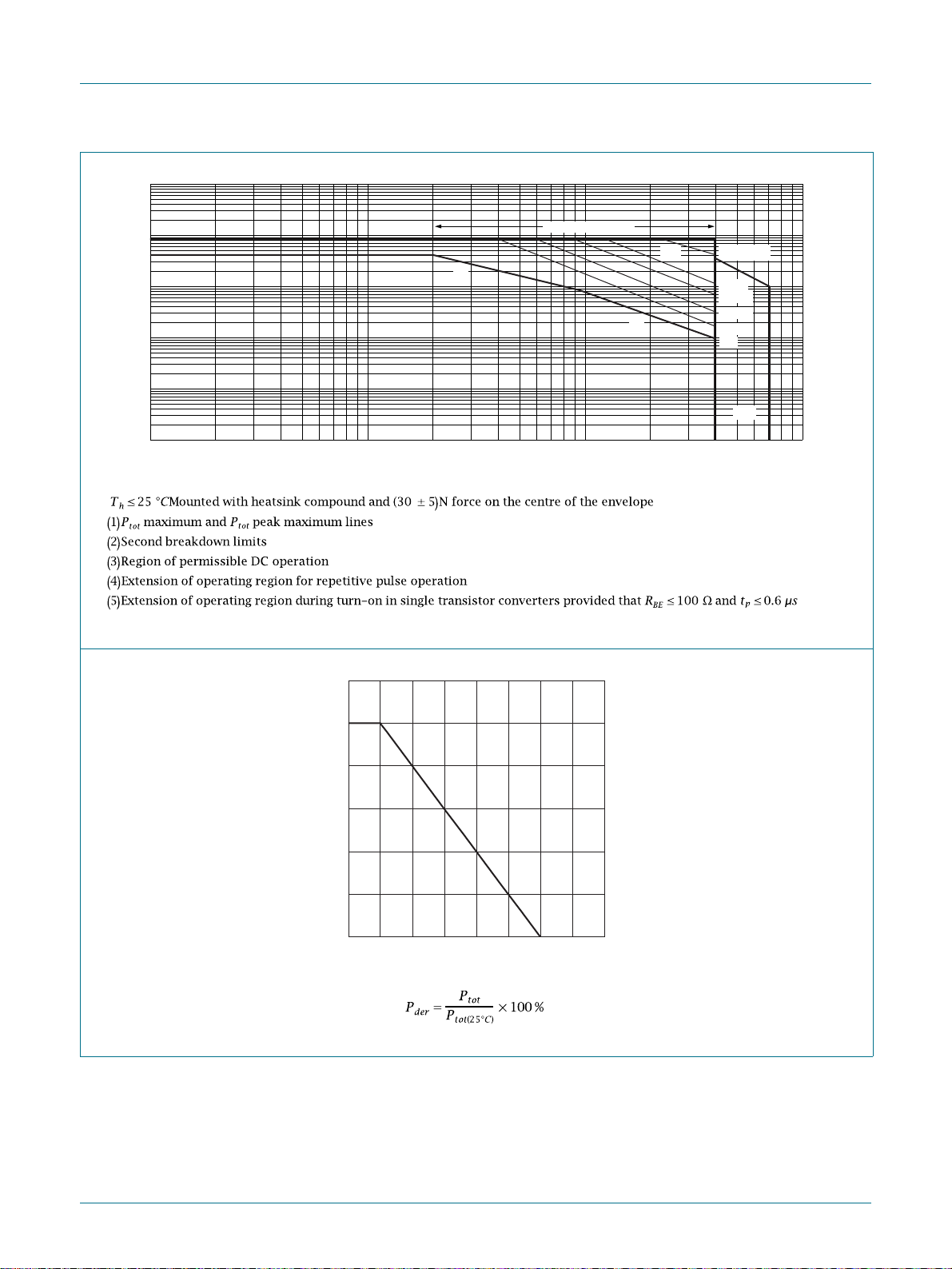
Fig 3. Forward bias safe operating area
001aai071
duty cycle = 0.01
CL(CE)
tp = 20 μs
50 μs
100 μs
200 μs
500 μs
DC
(5)
3
(V)
(4)
(1)
(2)
(3)
2
10
10
V
120
P
der
03aa13
(%)
80
40
0
0 50 100 150 200
T
(°C)
h
Fig 4. Normalized total power dissipation as a function of heatsink temperature
PHE13005X_2 © NXP B.V. 2009. All rights reserved.
Product data sheet Rev. 02 — 20 November 2009 4 of 13
Page 5
NXP Semiconductors
5. Thermal characteristics
PHE13005X
Silicon diffused power transistor
Table 5. Thermal characteristics
Symbol Parameter Conditions Min Typ Max Unit
R
th(j-h)
thermal resistance from
with heatsink compound; see Figure 5 --4.8K/W
junction to heatsink
R
th(j-a)
thermal resistance from
-55-K/W
junction to ambient
001aag169
t
p
δ =
1/f
1010
tp (s)
t
2
10
t
p
1/f
−1
110
Z
th(j-h)
(K/W)
10
10
10
10
δ = 0.5
0.2
1
0.1
0.05
0.02
−1
0
−2
−3
−6
−5
−4
10
10
10
P
−3
−2
10
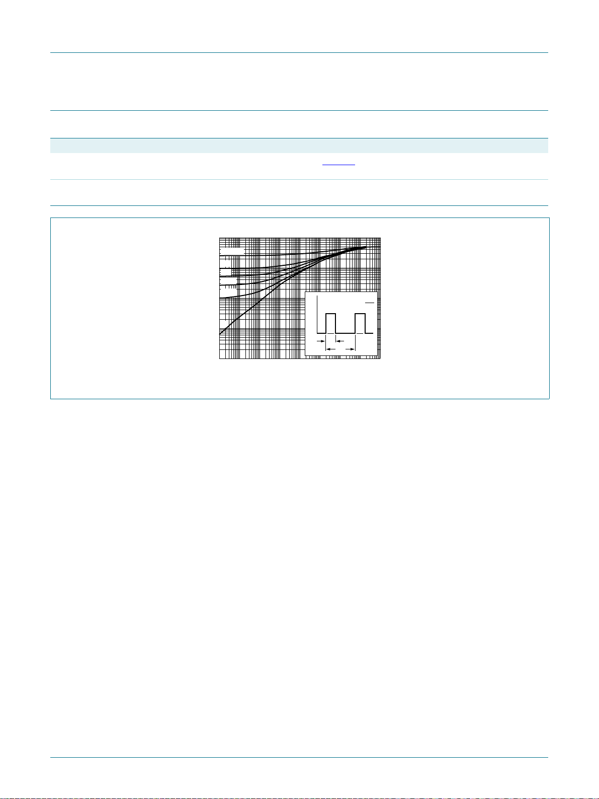
Fig 5. Transient thermal impedance from junction to heatsink as a function of pulse duration
PHE13005X_2 © NXP B.V. 2009. All rights reserved.
Product data sheet Rev. 02 — 20 November 2009 5 of 13
Page 6

NXP Semiconductors
6. Characteristics
PHE13005X
Silicon diffused power transistor
Table 6. Characteristics
Symbol Parameter Conditions Min Typ Max Unit
Static characteristics
I
CES
I
CBO
collector-emitter cut-off
current
collector-base cut-off
VBE=0V; VCE= 700 V; Tj=25°C --1mA
=0V; VCE= 700 V; Tj=100°C --5mA
V
BE
VCB=700V; IE=0A; Th=25°C --1mA
current
I
CEO
collector-emitter cut-off
VCE=400V; IB=0A; Th=25°C --0.1mA
current
I
EBO
emitter-base cut-off
VEB=9V; IC=0A; Th=25°C --1mA
current
V
CEOsus
V
CEsat
collector-emitter
sustaining voltage
collector-emitter
saturation voltage
IB=0A; IC=10mA; LC=25mH;
Th= 25 °C; see Figure 6 and 7
IC=1A; IB= 0.2 A; Th=25°C;
see Figure 8
I
=2A; IB= 0.5 A; Th=25°C;
C
and 9
400 - - V
-0.10.5V
-0.20.6V
see Figure 8 and 9
=4A; IB=1A; Th=25°C;
I
C
-0.31V
see Figure 8 and 9
V
BEsat
base-emitter saturation
voltage
IC=1A; IB= 0.2 A; Th=25°C;
see Figure 10
I
=2A; IB= 0.5 A; Th=25°C;
C
- 0.85 1.2 V
- 0.92 1.6 V
see Figure 10
h
FE
DC current gain IC=1A; VCE=5V; Th=25°C;
12 20 40
see Figure 11
I
=2A; VCE=5V; Th=25°C;
C
10 17 28
see Figure 11
Dynamic characteristi cs
t
s
storage time IC=2A; I
Bon
= 0.4 A; I
=-0.4A;
Boff
-2.74µs
RL=75Ω; Th= 25 °C; resistive load;
see Figure 12
I
=2A; I
C
and 13
= 0.4 A; VBB=-5V;
Bon
-1.22µs
LB=1µH; Th= 25 °C; inductive load;
see Figure 14 and 15
=2A; I
I
C
=1µH; Th= 100 °C; inductive load;
L
B
= 0.4 A; VBB=-5V;
Bon
-1.44µs
see Figure 14 and 15
t
f
fall time IC=2A; I
Bon
= 0.4 A; I
=-0.4A;
Boff
-0.30.9µs
RL=75Ω; Th= 25 °C; resistive load;
see Figure 13
I
=2A; I
C
and 12
= 0.4 A; VBB=-5V;
Bon
-0.10.5µs
LB=1µH; Th= 25 °C; inductive load;
see Figure 14 and 15
=2A; I
I
C
=1µH; Th= 100 °C; inductive load;
L
B
= 0.4 A; VBB=-5V;
Bon
- 0.16 0.9 µs
see Figure 14 and 15
PHE13005X_2 © NXP B.V. 2009. All rights reserved.
Product data sheet Rev. 02 — 20 November 2009 6 of 13
Page 7
NXP Semiconductors
87
001aab988
I
C
(mA)
PHE13005X
Silicon diffused power transistor
100 Ω to 200 Ω
horizontal
oscilloscope
vertical
6 V
30 Hz to 60 Hz
50 V
1 Ω300 Ω
001aab9
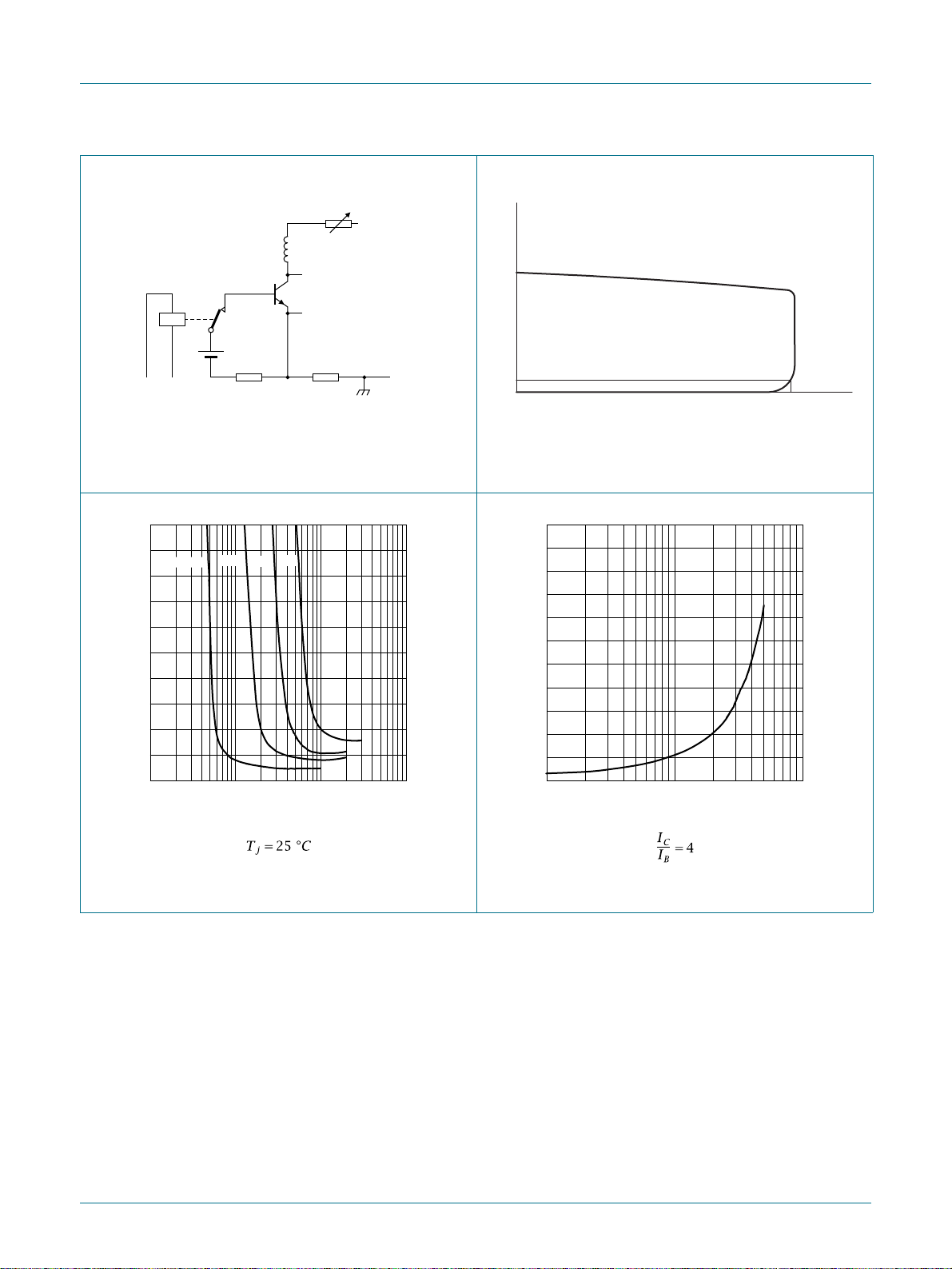
Fig 6. Test circuit for collector-emit ter sustaining
voltage
003aad540
V
CEsat
(V)
2.0
1.6
1.2
0.8
IC = 1 A
2 A
3 A
4 A
250
100
10
0
min
V
CEOsus
Fig 7. Oscilloscope display for collector-emitter
sustaining voltage test waveform
003aad542
V
CEsat
(V)
1.0
0.8
0.6
0.4
VCE (V)
0.4
0
−2
10
−1
IB (A)
10110
Fig 8. Collector-emitter saturation voltage; typical
values
0.2
0
−1
10
(A)
I
C
101
Fig 9. Collector-emitter saturation voltage as a
function of collector current; typical values
PHE13005X_2 © NXP B.V. 2009. All rights reserved.
Product data sheet Rev. 02 — 20 November 2009 7 of 13
Page 8
NXP Semiconductors
001aab990
001aab989
PHE13005X
Silicon diffused power transistor
I
C
(A)
003aad541
101
V
BEsat
(V)
1.4
1.2
1.0
0.8
0.6
0.4
0.2
0
−1
10
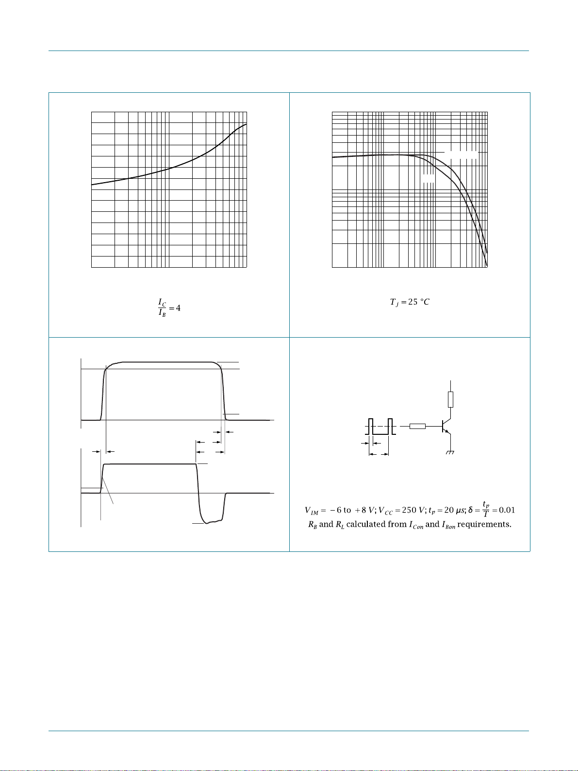
Fig 10. Base-emitter saturation voltage; typical values
I
C
90 %
I
Con
90 %
2
10
h
FE
1 V
10
1
−2
10
−1
003aad539
VCE = 5 V
IC (A)
10110
Fig 11. DC current gain as a function of collector
current; typical values
V
CC
10 %
t
f
s
I
Bon
10 %
Boff
t
t
off
I
B
t
on
tr ≤ 30 ns
−I
Fig 12. Switching times waveforms for resistive load
V
t
t
IM
0
t
p
T
R
B
Fig 13. Test circuit for resistive load switching
R
DUT
L
PHE13005X_2 © NXP B.V. 2009. All rights reserved.
Product data sheet Rev. 02 — 20 November 2009 8 of 13
Page 9
NXP Semiconductors
2
1
I
C
I
Con
90 %
PHE13005X
Silicon diffused power transistor
V
CC
L
C
10 %
t
t
s
t
I
off
Bon
I
B
f
−I
Boff
t
t
001aab99
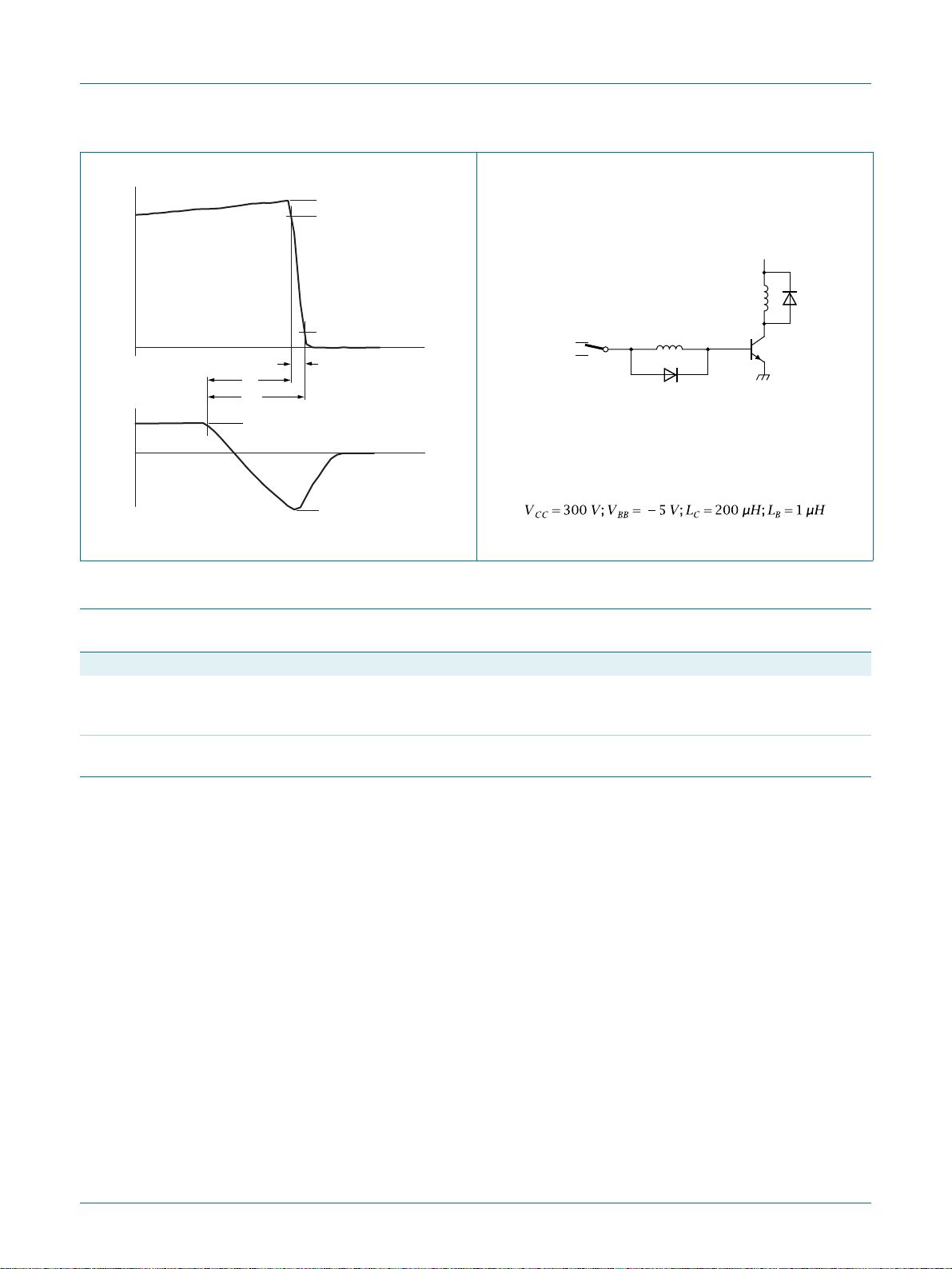
Fig 14. Switching times waveforms for inductive load
I
Bon
V
BB
Fig 15. Test circuit for inductive load switching
L
B
DUT
001aab99
7. Isolation characteristics
Table 7. Isolation characteristics
Symbol Parameter Conditions Min Typ Max Unit
V
isol(RMS)
C
isol
RMS isolation voltage 50 Hz ≤ f ≤ 60 Hz; RH ≤ 65 %; Th=25°C;
isolation capacitance from collector to external heatsink;
--2500V
from all terminals to external heatsink;
clean and dust free
-10-pF
f=1MHz; T
=25°C
h
PHE13005X_2 © NXP B.V. 2009. All rights reserved.
Product data sheet Rev. 02 — 20 November 2009 9 of 13
Page 10
NXP Semiconductors
A
8. Package outline
Plastic single-ended package; isolated heatsink mounted;
1 mounting hole; 3-lead TO-220 'full pack'
PHE13005X
Silicon diffused power transistor
SOT186
E
P
q
D
1
D
L
2
b
L
1
b
2
23
1
b
e
e
1
T
L
1
w M
mounting
base
A
A
1
j
K
Q
c
0 5 10 mm
scale
DIMENSIONS (mm are the original dimensions)
A
A
b
UNIT
mm
Notes
1. Terminal dimensions within this zone are uncontrolled.
2. Both recesses are ∅ 2.5 × 0.8 max. depth
OUTLINE
VERSION
SOT186A 3-lead TO-220F
4.6
4.0
1
2.9
2.5
b
1
1.1
0.9
0.9
0.7
IEC JEDEC JEITA
b
1.4
1.0
c
0.7
0.4
D
15.8
15.2
2
E
D
1
6.5
10.3
9.7
2.54
6.3
REFERENCES
e
e
j
2.7
1.7
0.6
0.4
K
14.4
13.5
1
5.08
L
3.30
2.79
1
(1)
L
2
max.
3.2
3
3.0
EUROPEAN
PROJECTION
2.6
2.3
(2)
qQPL
T
3.0
2.5 0.4
2.6
ISSUE DATE
02-04-09
06-02-14
w
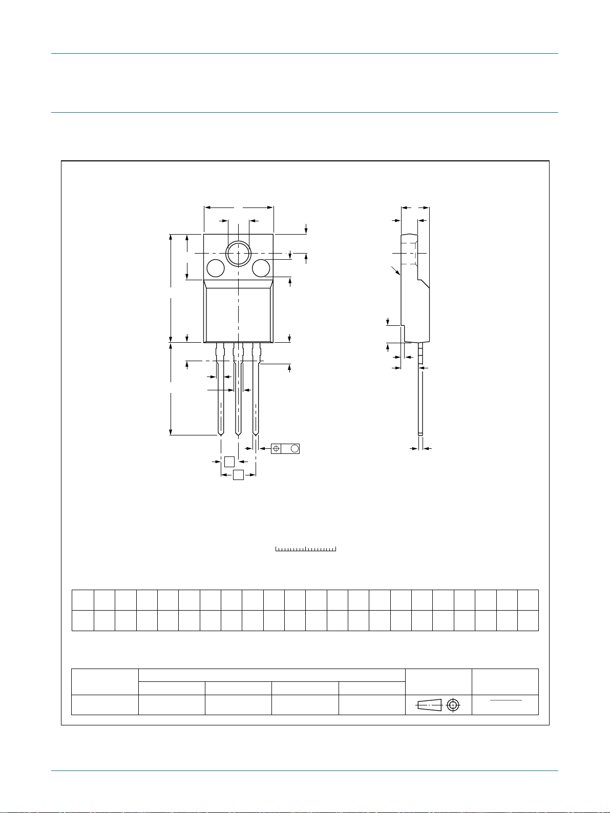
Fig 16. Package outline SOT186A (TO-220F)
PHE13005X_2 © NXP B.V. 2009. All rights reserved.
Product data sheet Rev. 02 — 20 November 2009 10 of 13
Page 11

NXP Semiconductors
9. Revision history
PHE13005X
Silicon diffused power transistor
Table 8. Revision history
Document ID Release date Data sheet status Change notice Supersedes
PHE13005X_2 20091120 Product data sheet - PHE13005X_1
Modifications:
PHE13005X_1 20080515 Product data sheet - -
• Various changes to content.
PHE13005X_2 © NXP B.V. 2009. All rights reserved.
Product data sheet Rev. 02 — 20 November 2009 11 of 13
Page 12

NXP Semiconductors
PHE13005X
Silicon diffused power transistor
10. Legal information
10.1 Data sheet status
Document status
Objective [short] data sheet Development This document contains data from the objective specification for product development.
Preliminary [short] data sheet Qualification This document contains data from the preliminary specification.
Product [short] data sheet Production This document contains the product specification.
[1] Please consult the most recently issued document before initiating or completing a design.
[2] The term 'short data sheet' is explained in section "Definitions".
[3] The product status of device(s) described in this document may have changed since this document was published and may differ in case of multiple devices. The latest product
status information is available on the Internet at URL http://www.nxp.com
[1][2]
Product status
[3]
Definition
.
10.2 Definitions
Draft — The document is a draft version only. The content is still under
internal review and subject to formal approval, which may result in
modifications or additions. NXP Semiconductors does not give any
representations or warranties as to the accuracy or completeness of
information included herein and shall have no liability for the consequences of
use of such information.
Short data sheet — A short data sheet is an extract from a full dat a sheet
with the same product type number(s) and title. A short data sheet is intended
for quick reference only and should not be relied u pon to co nt ain det ailed and
full information. For detailed and full information see the relevant full data
sheet, which is available on request via the local NXP Semiconductors sales
office. In case of any inconsistency or conflict with the short data sheet, the
full data sheet shall prevail.
10.3 Disclaimers
General — Information in this document is believed to be accurate and
reliable. However, NXP Semiconduct ors does not give any repr esentatio ns or
warranties, expressed or implied, as to the accuracy or completeness of such
information and shall have no liability for the consequences of use of such
information.
Right to make changes — NXP Semiconductors reserves the right to make
changes to information published in this document, including without
limitation specifications and product descriptions, at any time and without
notice. This document supersedes and replaces all information supplied prior
to the publication hereof.
Suitability for use — NXP Semiconductors products are not designed,
authorized or warranted to be suitable for use in medical, military, aircraft,
space or life support equipment, nor in applications where failure or
malfunction of an NXP Semiconductors product can reasonably be expected
to result in personal injury, death or severe property or environmental
damage. NXP Semiconductors accepts no liability for inclusion and/or use of
NXP Semiconductors products in such equipment or applications and
therefore such inclusion and/or use is at the customer’s own risk.
Applications — Applications that are described herein for any of these
products are for illustrative purposes only. NXP Semiconductors makes no
representation or warranty that such applications will be suitable for the
specified use without further testing or modification.
Quick reference data — The Quick reference data is an extract of the
product data given in the Limiting values and Characteri stics sections of this
document, and as such is not complete, exhaustive or legally binding.
Limiting values — Stress above one or more limiting values (as defined in
the Absolute Maximum Ratings System of IEC 60134) may cause permanent
damage to the device. Limiting values are stress ratings only and operation of
the device at these or any other conditions above those given in the
Characteristics sections of this document is not implied. Exposure to limiting
values for extended periods may affect device reliability.
Terms and conditions of sale — NXP Semiconductors products are sold
subject to the general terms and conditions of commercial sale, as published
at http://www.nxp.com/profile/terms
intellectual property rights infringement and limitation of liability, unless
explicitly otherwise agreed to in writing by NXP Semiconductors. In case of
any inconsistency or conflict between information in this document and such
terms and conditions, the latter will prevail.
No offer to sell or license — Nothing in this document may be interpreted or
construed as an offer to sell product s that is ope n for accept ance or the gr ant,
conveyance or implication of any license under any copyrights, patents or
other industrial or intellectual property rights.
Export control — This document as well as the item(s) described herein may
be subject to export control regulations. Export might require a prior
authorization from national authorities.
, including those pertaining to warranty,
10.4 Trademarks
Notice: All referenced brands, product names, service names and trademarks
are the property of their respective owners.
11. Contact information
For more information, please visit: http://www.nxp.com
For sales office addresses, please send an email to: [email protected]
PHE13005X_2 © NXP B.V. 2009. All rights reserved.
Product data sheet Rev. 02 — 20 November 2009 12 of 13
Page 13

NXP Semiconductors
12. Contents
1 Product profile . . . . . . . . . . . . . . . . . . . . . . . . . . .1
1.1 General description . . . . . . . . . . . . . . . . . . . . . .1
1.2 Features and benefits. . . . . . . . . . . . . . . . . . . . .1
1.3 Applications . . . . . . . . . . . . . . . . . . . . . . . . . . . .1
1.4 Quick reference data . . . . . . . . . . . . . . . . . . . . .1
2 Pinning information. . . . . . . . . . . . . . . . . . . . . . .2
3 Ordering information. . . . . . . . . . . . . . . . . . . . . .2
4 Limiting values. . . . . . . . . . . . . . . . . . . . . . . . . . .3
5 Thermal characteristics . . . . . . . . . . . . . . . . . . .5
6 Characteristics. . . . . . . . . . . . . . . . . . . . . . . . . . .6
7 Isolation characteristics . . . . . . . . . . . . . . . . . . .9
8 Package outline . . . . . . . . . . . . . . . . . . . . . . . . .1 0
9 Revision history. . . . . . . . . . . . . . . . . . . . . . . . .11
10 Legal information. . . . . . . . . . . . . . . . . . . . . . . .12
10.1 Data sheet status . . . . . . . . . . . . . . . . . . . . . . .12
10.2 Definitions. . . . . . . . . . . . . . . . . . . . . . . . . . . . .12
10.3 Disclaimers . . . . . . . . . . . . . . . . . . . . . . . . . . . .12
10.4 Trademarks. . . . . . . . . . . . . . . . . . . . . . . . . . . .12
11 Contact information. . . . . . . . . . . . . . . . . . . . . .12
PHE13005X
Silicon diffused power transistor
Please be aware that important notices concerning this document and the product(s)
described herein, have been included in section ‘Legal information’.
© NXP B.V. 2009. All rights reserved.
For more information, please visit: http://www.nxp.com
For sales office addresses, please send an email to: [email protected]
Date of release: 20 November 2009
Document identifier: PHE13005X_2
 Loading...