

Philips PDIUSBH11NB, PDIUSBH11D Datasheet

INTEGRATED CIRCUITS
PDIUSBH11
Universal Serial Bus Hub
Product specification
Supersedes data of 1997 Apr 17
1997 Aug 01
Philips Semiconductors Product specification
PDIUSBH1 1Universal Serial Bus Hub
FEA TURES
•Complies with the Universal Serial Bus specification Rev. 1.0
•Four downstream ports with per packet connectivity
•Embedded function with two endpoints (control and interrupt)
•Integrated FIFO memory for hub and embedded function
•Automatic protocol handling
•Versatile I
2
C interface
•Allows software control of monitor
•Compliant with USB Human Interface and Display Device Class
•Single 3.3V supply with 5V tolerant I/O
DESCRIPTION
The Philips Semiconductors PDIUSBH1 1 is a compound USB hub
IC (hub plus embedded function).
It is used in a microcontroller based system and communicates with
the system microcontroller over the I
approach to implementing a hub and embedded function allows the
designer to maintain the system microcontroller of choice and retain
existing architecture. This cuts down development time and offers
the most cost-effective solution.
Ideal applications for the IC include computer monitors and
keyboards.
The PDIUSBH11 conforms to the USB specification 1.0 and I
serial interface specification. It is also compliant with the USB
Human Input Device and Monitor Control Class specifications.
2
C serial bus. This modular
The embedded function of the PDIUSBH11 appears as PORT1 to
the host system and the four downstream ports are numbered 2
through 5.
ORDERING INFORMATION
PACKAGES TEMPERATURE RANGE OUTSIDE NORTH AMERICA NORTH AMERICA PKG. DWG. #
32-pin plastic SO 0°C to +70°C PDIUSBH11 D PDIUSBH11 D SOT287-1
32-pin plastic SDIP 0°C to +70°C PDIUSBH11 NB PDIUSBH11 NB SOT232-1
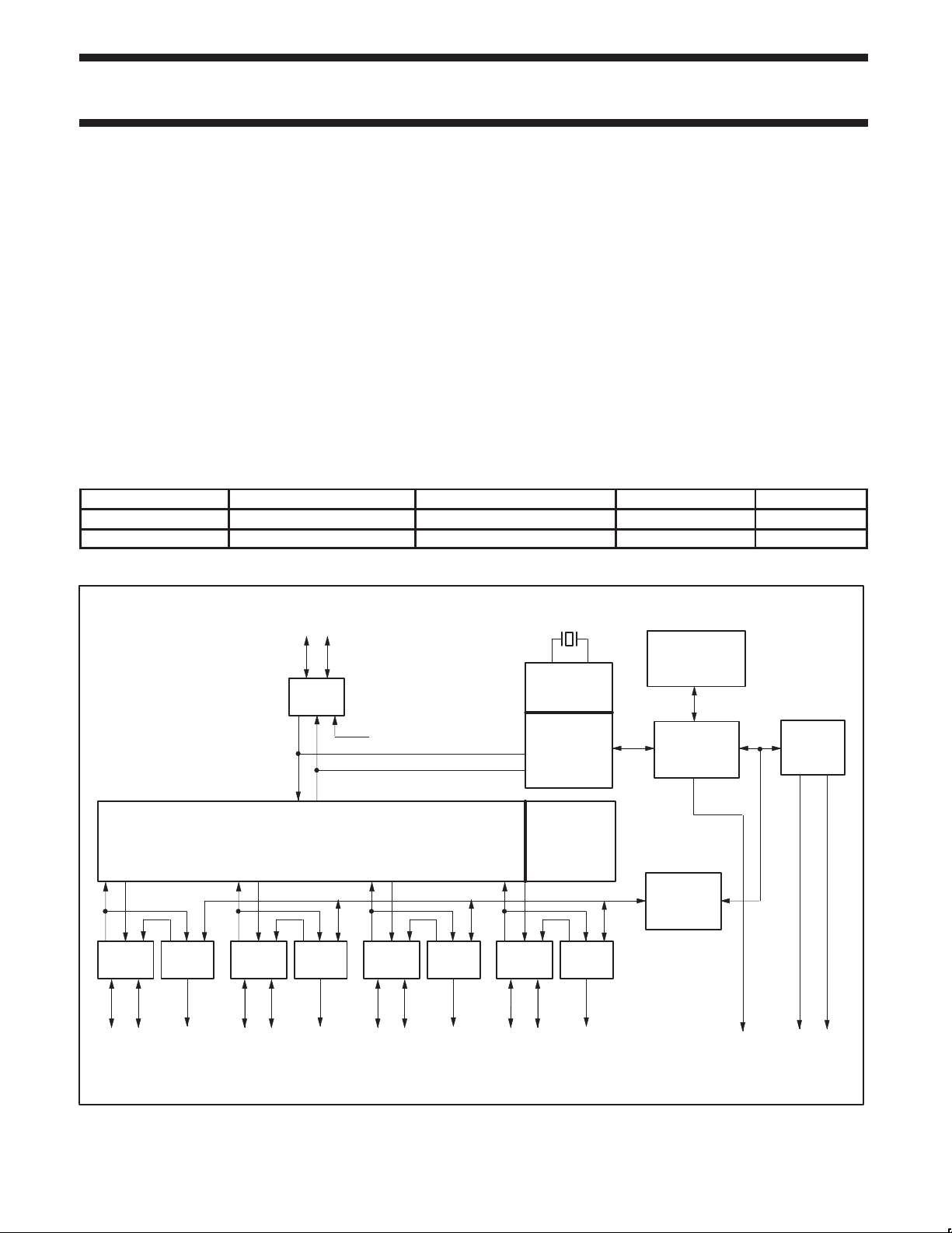
BLOCK DIAGRAM
UPSTREAM
PORT
D+
ANALOG
T
X/RX
D–
48 MHz
BIT CLOCK
RECOVERY
INTEGRATED
RAM
2
C
FULL SPEED
HUB
REPEATER
ANALOG
T
X/RX
D–D+
DOWNSTREAM
PORT 2
PORT
CONTROL
LED
ENABLE
ANALOG
T
X/RX
D–D+
DOWNSTREAM
PORT 3
PORT
CONTROL
LED
ENABLE
ANALOG
T
X/RX
D–D+
DOWNSTREAM
PORT 4
PORT
CONTROL
LED
ENABLE
ANALOG
T
X/RX
DOWNSTREAM
PORT 5
NOTE:
1. This is a conceptual block diagram and does not include each individual signal.
PHILIPS
SIE
END OF
FRAME
TIMERS
D–D+
PORT
CONTROL
LED
ENABLE
MEMORY
MANAGEMENT
UNIT
GENERAL
PORT
CONTROLLER
2
C
I
SLAVE
INTERFACE
INTERRUPT SDA SCL
SV00226
1997 Aug 01 853–1968 18238
2

Philips Semiconductors Product specification
HUB
PDIUSBH11Universal Serial Bus Hub
Analog Transceivers
These transceivers interface directly to the USB cables through
some termination resistors. They are capable of transmitting and
receiving serial data at both “full speed” (12 Mbit/s) and “low speed”
(1.5 Mbit/s) data rates.
Hub Repeater
The hub repeater is responsible for managing connectivity on a per
packet basis. It implements packet signaling connectivity and
resume connectivity.
Low speed devices can be connected to downstream ports since the
repeater will not propagate upstream packets to downstream ports,
to which low speed devices are connected, unless they are
preceded by a PREAMBLE PID.
End of Frame Timers
This block contains the specified EOF1 and EOF2 timers which are
used to detect loss-of-activity and babble error conditions in the hub
repeater. The timers also maintain the low-speed keep-alive strobe
which is sent at the beginning of a frame.
General and Individual Port Controller
The general and individual port controllers together provide status
and control of individual downstream ports. Via the I
2
C-interface a
microcontroller can access the downstream ports and request or
change the status of each individual port.
Any change in the status or settings of the individual port will result
in an interrupt request. Via an interrupt register, the servicing
microcontroller can look up the downstream port which generated
ENDPOINT DESCRIPTIONS
The following table summarizes the endpoints supported by the PDIUSBH11.
FUNCTION
EMBEDDED
ENDPOINT
NUMBER
ENDPOINT TYPE TRANSFER TYPE DIRECTION
0 Default Control IN, OUT 8
1 Status change Interrupt IN 1
0 Default Control IN, OUT 8
1 Interrupt Interrupt IN 8
the interrupt and request its new status. Any port status change can
then be reported to the host via the hub status change (interrupt)
endpoint.
Bit Clock Recovery
The bit clock recovery circuit recovers the clock from the incoming
USB data stream using (4X) over-sampling principle. It is able to
track jitter and frequency drift specified by the USB spec.
Philips Serial Interface Engine (PSIE)
The Philips SIE implements the full USB protocol layer. It is
completely hardwired for speed and needs no firmware intervention.
The functions of this block include: synchronization pattern
recognition, parallel / serial conversion, bit stuffing / destuffing, CRC
checking / generation, PID verification / generation, address
recognition, handshake evaluation / generation.
Memory Management Unit (MMU) and Integrated RAM
The MMU and the integrated RAM is used to handle the large
difference in data-rate between USB, running in burst of 12 Mbit/s
and the I
This allows the microcontroller to read and write USB packets at its
own (low) speed through I
I
This block implements the necessary I
I
microcontroller whenever the PDIUSBH11 needs attention. As a
slave I
2
C interface to the microcontroller, running at 100 kbit/s.
2
C.
2
C Slave Interface
2
C allows for simple micro-coding. An interrupt is used to alert the
2
C device, the PDIUSBH11 I2C clock: SCL is an input and is
2
C interface protocol. A slave
controlled by the microcontroller.
MAXIMUM PACKET SIZE
(bytes)
PIN DESCRIPTION
The PDIUSBH11 has two modes of operation. The first mode
(Mode 0) enables the pins DNx_EN_N to power a LED indicating
the port is enabled. The second mode (Mode 1) utilizes the LED
enable pins as per port overcurrent condition pins.
1997 Aug 01
The voltage level at power up on the TEST1 and TEST2 pins
determine the PDIUSBH1 1 mode of operation. When both of the
pins are connected to Ground, Mode 0 is enabled. When pins
TEST1 and TEST2 are connected to Vcc, Mode 1 is enabled. Note
that in Mode 1 the pin DN2_EN_N remains an LED enable pin. Pin
TEST3 should always be connected to Ground at all times.
3

Philips Semiconductors Product specification
PDIUSBH11Universal Serial Bus Hub
PIN DESCRIPTION (MODE 0)
PIN NO PIN SYMBOL I/O DRIVE NAME AND FUNCTION
1 TEST1 I Connect to Ground
2 TEST2 I Connect to Ground
3 TEST3 I Connect to Ground
4 RESET_N I ST Power-on reset
5 GND POWER Ground reference
6 XTAL1 I/O Crystal connection 1 (48MHz)
7 XTAL2 I/O Crystal connection 2 (48MHz)
8 CLK12MHZ O 2mA 12MHz output clock for external devices
9 V
10 OCURRENT_N I ST Over-current notice to the device
11 SWITCH_N O OD8 Enables power to downstream ports
12 SUSPEND O 4mA Device is in suspended state
13 DN2_EN_N O OD8 Downstream port 2 LED enable indicator
14 DN3_EN_N O OD8 Downstream port 3 LED enable indicator
15 DN4_EN_N O OD8 Downstream port 4 LED enable indicator
16 DN5_EN_N O OD8 Downstream port 5 LED enable indicator
17 INT_N O OD4 Connect to microcontroller interrupt
18 SDA I/O OD4 I2C bi-directional data
19 SCL I/O OD4 I2C bit-clock
20 GND POWER Ground reference
21 DN5_DP AI/O Downstream port 5 D+ connection
22 DN5_DM AI/O Downstream port 5 D– connection
23 DN4_DP AI/O Downstream port 4 D+ connection
24 DN4_DM AI/O Downstream port 4 D– connection
25 DN3_DP AI/O Downstream port 3 D+ connection
26 DN3_DM AI/O Downstream port 3 D– connection
27 DN2_DP AI/O Downstream port 2 D+ connection
28 DN2_DM AI/O Downstream port 2 D- connection
29 AGND POWER Analog Ground reference
30 AV
31 UP_DP AI/O Upstream D+ connection
32 UP_DM AI/O Upstream D- connection
CC
CC
POWER
POWER
Voltage supply 3.3V 0.3V
Analog voltage supply 3.3V 0.3V
1997 Aug 01
4

Philips Semiconductors Product specification
PDIUSBH11Universal Serial Bus Hub
PIN DESCRIPTION (MODE 1)
PIN NO PIN SYMBOL I/O DRIVE NAME AND FUNCTION
1 TEST1 I Connect to V
2 TEST2 I Connect to V
3 TEST3 I Connect to Ground
4 RESET_N I ST Power-on reset
5 GND POWER Ground reference
6 XTAL1 I/O Crystal connection 1 (48MHz)
7 XTAL2 I/O Crystal connection 2 (48MHz)
8 CLK12MHZ O 2mA 12MHz output clock for external devices
9 V
10 OCURRENT2_N I ST Downstream port 2 over-current notice
11 SWITCH_N O OD8 Enables power to downstream ports
12 SUSPEND O 4mA Device is in suspended state
13 DN2_EN_N O OD8 Downstream port 2 LED enable indicator
14 OCURRENT3_N I ST Downstream port 3 over-current notice
15 OCURRENT4_N I ST Downstream port 4 over-current notice
16 OCURRENT5_N I ST Downstream port 5 over-current notice
17 INT_N O OD4 Connect to microcontroller interrupt
18 SDA I/O OD4 I2C bi-directional data
19 SCL I/O OD4 I2C bit-clock
20 GND POWER Ground reference
21 DN5_DP AI/O Downstream port 5 D+ connection
22 DN5_DM AI/O Downstream port 5 D– connection
23 DN4_DP AI/O Downstream port 4 D+ connection
24 DN4_DM AI/O Downstream port 4 D- connection
25 DN3_DP AI/O Downstream port 3 D+ connection
26 DN3_DM AI/O Downstream port 3 D- connection
27 DN2_DP AI/O Downstream port 2 D+ connection
28 DN2_DM AI/O Downstream port 2 D- connection
29 AGND POWER Analog Ground reference
30 AV
31 UP_DP AI/O Upstream D+ connection
32 UP_DM AI/O Upstream D- connection
NOTES:
1. Signals ending in _N indicate active low signals.
ST: Schmitt Trigger
OD4, OD8: Open Drain with 4 or 8 mA drive
AI/O: Analog I/O
CC
CC
POWER
POWER
Voltage supply 3.3V 0.3V
Analog voltage supply 3.3V 0.3V
CC
CC
1997 Aug 01
5
Philips Semiconductors Product specification
PDIUSBH11Universal Serial Bus Hub
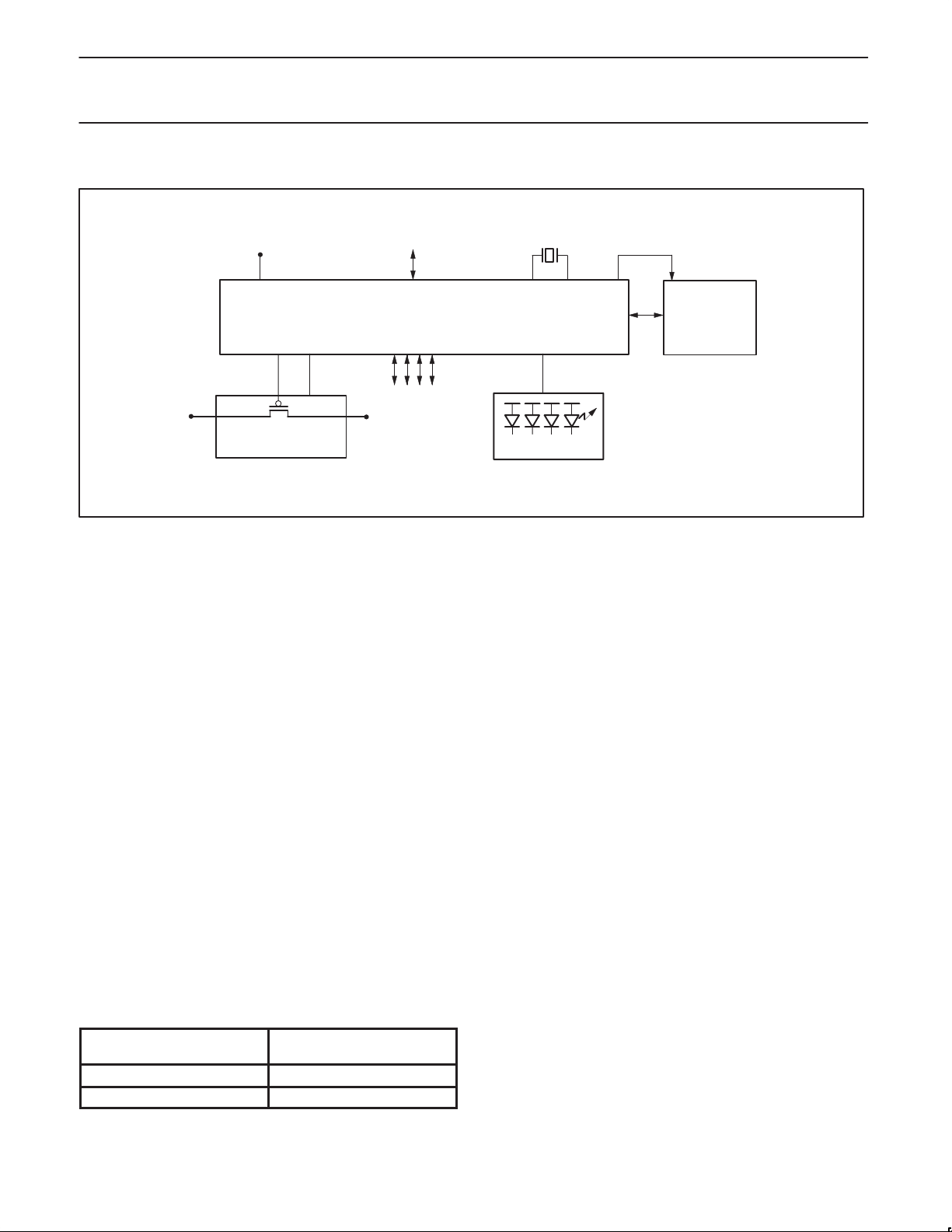
APPLICATION DIAGRAM
USB
3.3V
UPSTREAM
48MHz
12MHz
H11
USB
5V
POWER SWITCH
AND
OVERCURRENT CIRCUIT
I2C Interface.
2
The I
C bus is used to interface to an external microcontroller
DOWNSTREAM
SWITCHED
5V
needed to control the operation of the hub. For cost consideration,
the target system microcontroller can be shared and utilized for this
purpose. The PDIUSBH11 implements a slave I
2
C interface. When
the PDIUSBH11 needs to communicate with the microcontroller it
asserts an interrupt signal. The microcontroller services this
interrupt by reading the appropriate status register on the
PDIUSBH11 through the I
2
I
C serial bus, refer to the I2C handbook, Philips order number 9397
2
C bus. (For more information about the
750 00013).
2
The I
C interface on the PDIUSBH11 defines two types of
transactions :
1. command transaction
A command transaction is used to define which data (e.g., status
byte, buffer data, ...) will be read from / written to the USB
interface in the next data transaction. A data transaction usually
follows a command transaction.
2. data transaction
A data transaction reads data from / writes data to the USB
interface. The meaning of the data is dependent on the
command transaction which was sent before the data
transaction.
I2C
ENABLE LED
Protocol
2
An I
C transaction starts with a ‘Start Condition’, followed by an
µC
SV00227
address. When the address matches either the command or data
address the transaction starts and runs until a ‘Stop Condition’ or
another ‘Start Condition’ (repeated start) occurs.
The command address is write-only and is unable to do a read. The
next bytes in the message are interpreted as commands. Several
command bytes can be sent after one command address. Each of
the command bytes is acknowledged and passed on to the Memory
Management Unit inside the PDIUSBH11.
When the start condition address matches the data address, the
next bytes are interpreted as data. When the RW bit in the address
indicates a ‘master writes data to slave’ (=‘0’) the bytes are received,
acknowledged and passed on to the Memory Management Unit. If
the RW bit in the address indicates a ‘master reads data from slave’
(=‘1’) the PDIUSBH11 will send data to the master. The I
must acknowledge all data bytes except the last one. In this way the
2
I
C interface knows when the last byte has been transmitted and it
2
C-master
then releases the SDA line so that the master controller can
generate the STOP condition.
Repeated start support allows another packet to be sent without
generating a Stop Condition.
Two addresses are used to differentiate between command and
data transactions. Writing to the command address is interpreted as
a command, while reading from / writing to the data address is used
to transfer data between the PDIUSBH11 and the controller.
ADDRESS TABLE
TYPE OF ADDRESS
Command 0011 011 (binary)
Data 0011 010 (binary)
1997 Aug 01
PHYSICAL ADDRESS
(MSB to LSB)
Timing
When the master writes data to the PDIUSBH11, the data is
sampled 1 micro-second after the rising edge of SCL. When the
PDIUSBH11 writes data to the master, the data is driven 1
micro-second after the falling edge of SCL.
6

Philips Semiconductors Product specification
PDIUSBH11Universal Serial Bus Hub
COMMAND SUMMARY
Some commands have the same command code (e.g., Read Buffer and Write Buffer). In these cases, the direction of the Data Phase (read or
write) indicates which command is executed.
COMMAND NAME
Initialization Commands
Set Address / Enable Hub D0h Write 1 byte
Set Endpoint Enable Hub + Embedded Function D8h Write 1 byte
Data Flow Commands
Read Interrupt Register F4h Read 1 byte
Select Endpoint Hub Control OUT 00h Read 1 byte (optional)
Embedded Function Control OUT 02h Read 1 byte (optional)
Embedded Function Control IN 03h Read 1 byte (optional)
Embedded Function Interrupt 04h Read 1 byte (optional)
Read Last Transaction Status Hub Control OUT 40h Read 1 byte
Embedded Function Control OUT 42h Read 1 byte
Embedded Function Control IN 43h Read 1 byte
Embedded Function Interrupt 44h Read 1 byte
Read Endpoint Status Hub Control OUT 80h Read 1 byte
Embedded Function Control OUT 82h Read 1 byte
Embedded Function Control IN 83h Read 1 byte
Embedded Function Interrupt 84h Read 1 byte
Read Buffer Selected Endpoint F0h Read n bytes
Write Buffer Selected Endpoint F0h Write n bytes
Set Endpoint Status Hub Control OUT 40h Write 1 byte
Embedded Function Control OUT 42h Write 1 byte
Embedded Function Control IN 43h Write 1 byte
Embedded Function Interrupt 44h Write 1 byte
Acknowledge Setup Selected Endpoint F1h None
Clear Buffer Selected Endpoint F2h None
Validate Buf fer Selected Endpoint FAh None
Hub Commands
Clear Port Feature Port 2 E0h Write 1 byte
Set Port Feature Port 2 E8h Write 1 byte
Get Port Status Port 2 E0h Read 1 or 2 bytes
Set Status Change Bits F7h Write 1 byte
General Commands
Send Resume F6h None
Read Current Frame Number F5h Read 1 or 2 bytes
RECIPIENT CODING DATA PHASE
Embedded Function D1h Write 1 byte
Hub Control IN 01h Read 1 byte (optional)
Hub Control IN 41h Read 1 byte
Hub Control IN 81h Read 1 byte
Hub Control IN 41h Write 1 byte
Port 3 E1h Write 1 byte
Port 4 E2h Write 1 byte
Port 5 E3h Write 1 byte
Port 3 E9h Write 1 byte
Port 4 EAh Write 1 byte
Port 5 EBh Write 1 byte
Port 3 E1h Read 1 or 2 bytes
Port 4 E2h Read 1 or 2 bytes
Port 5 E3h Read 1 or 2 bytes
1997 Aug 01
7

Philips Semiconductors Product specification
PDIUSBH11Universal Serial Bus Hub
COMMAND DESCRIPTIONS
Command Procedure
There are four basic types of commands: Initialization, Data, Hub Specific and General commands. Respectively, these are used t o initialize the
hub and embedded function; for data flow between the hub, embedded function and the host; some hub specific commands for controlling
individual downstream ports; and some general commands.
Initialization Commands
Initialization commands are used during the enumeration process of the USB network. These commands are used to enable the hub and
embedded function endpoints. They are also used to set the USB assigned address.
Set Address / Enable
Command : D0h (Hub), D1h (Embedded Function)
Data : Write 1 byte
This command is used to set the USB assigned address and enable the hub or embedded function respectively. The hub always powers up
disabled and should be enabled after a bus RESET.
706050403020100
0
ADDRESS THE VALUE WRITTEN BECOMES THE ADDRESS
ENABLE A ‘1’ ENABLES THIS FUNCTION
POWER ON VALUE
ADDRESS
ENABLE
SV00385
Set Endpoint Enable
Command : D8h
Data : Write 1 byte
Interrupt endpoints can only be enabled when the hub/function is enabled via the Set Address/Enable command.
7X6X5X4X3X20100
X
POWER ON VALUE
HUB’S INTERRUPT ENDPOINT
FUNCTION’S INTERRUPT ENDPOINT
RESERVED
1997 Aug 01
HUB’S INTERRUPT ENDPOINT A VALUE OF ‘1’ INDICATES THE HUB’S INTERRUPT ENDPOINT IS ENABLED.
FUNCTION’S INTERRUPT ENDPOINT A VALUE OF ‘1’ INDICATES THE EMBEDDED FUNCTION’S INTERRUPT ENDPOINT IS ENABLED.
SV00387
8
 Loading...