

Page 1
TiVD^Komiri'
fnitrticcionf for Ui*
UfhmiiitiuysieltixC
PHILIPS
Page 2

PCA532 DK01
U55eriXK№iir'~
15861385 I
SERIAL NUHiEK
---
LASER SAFETY
This DVD drive employs a laser. Do not remove the cover or attempt to service this device
when connected due to the possibility of eye damage.
CLASS 1
LASER PRODUCT
CAUTION
USE OF CONTROLS OR ADJUSTMENTS OR PERFORMANCE OF
PROCEDURES OTHER THAN THOSE SPECIFIED HEREIN MAY RESULT IN
HAZARDOUS LASER RADIATION EXPOSURE.
CAUTION
LASER RADIATION WHEN OPEN AVOID EXPOSURE TO BEAM.
FOR EUROPE
a
The DVD-ROM drive is in conformity with the EMC directive and low-voltage
directive.
Philips DVD/ROM kit
Page 3

©1998 Philips Electronics b.v. All Rights Reserved.
Septembers, 1998
Information in this manual is subject to change without notice. The software described in
this manual is furnished under license and may be used or copied only in accordance with the
license agreement. It is unlawful to copy the software except as specified in the license agree
ment. No part of this manual may be reproduced or transmitted in any form or by any
means, electronic or mechanical, including photocopying or scanning, for any purpose,
without the express written permission of Sigma Designs, Inc.
REALmagic, REALmagic Hollywood Plus, REALmagic In it, REAL Overlay are trademarks
of Sigma Designs Inc., Sigma Designs and the Sigma Designs logo are registered trademarks
of Sigma Designs Inc., Microsoft, MS and MS-DOS are registered trademarks of Microsoft
Corporation. As used in this manual, Windows refers to Microsoft Windows, Microsoft
Corporation’s implementation of a windowing system. IBM, DOS, PC and VGA are trade
marks of International Business Machines Corporation. Dolby, AC-3, Pro Logic, and the
double-D symbol are trademarks of Dolby Laboratories. All other brand and product names
referred to in this manual are trademarks or registered trademarks of their respective holders.
REALmagic Hollywood Plus is manufactured under license from Dolby Laboratories. Copy
right 1992 Dolby Laboratories, Inc. All rights reserved.
Philips reserves the right to use or distribute any information you supply to its Customer
Service Center in any way it deems appropriate without incurring any obligation whatsoever.
Page 4

FCC Compliance Statement
This equipment has been tested and found to comply with the limits for a Class B digital
device, pursuant to Part 15 of the FCC Rules. These limits are designed to provide reasonable
protection against harmful interference in residential installation. This equipment generates,
uses, and can radiate radio frequency energy and, if not installed and used in accordance with
the instructions, may cause harmful interference to radio communications. However, there is
no guarantee that interference will not occur in a particular installation. If this equipment does
cause interference to radio or television reception, which can be determined by turning the
equipment off and on, the user is encouraged to try to correct the interference by one or more
of the following measures:
• Reorient or relocate the receiving antenna.
• Increase the separation between the equipment and receiver.
• Connect the equipment into an outlet on a circuit different from that to which the recei
ver is connected.
• Consult the dealer or an experienced radio/TV technician for help.
Notice
This device complies with Part 15 of the FCC rules. Operation is subject to the following
two conditions: (1) this device may not cause harmful interference, and (2) this device must
accept any interference received, including interference that may cause undesired operation.
Shielded cables and I/O cords must be used for this equipment to comply with the relevant
FCC regulations.
Changes or modifications not expressly approved in writing by Philips, may void the user’s
authority to operate this equipment. This digital apparatus does not exceed the Class B limits
for radio noise emissions from digital apparatus set out in the radio interference regulation of
the Canadian Department of Communication.
2 Philips DVD/ROM kit
Page 5

Contents
Chapter 1:.........................................................................................................................................4
Introduction .............................................................................................................................4
Philips DVD-ROM Drive .................................................................................................4
REALmagic Hollywood Plus DVD/MPEG-2 Playback Card
System Requirements .................................................................................................5
Chapter 2:.........................................................................................................................................6
Hardware Installation ..............................................................................................................6
Installing the DVD-ROM drive........................................................................................6
Checking the IDE Controller......................................................................................6
Jumper Setup ...............................................................................................................7
Eject Suppression Switch (PRV/ALW) .....................................................................7
Setting the Master/Slave Jumper................................................................................7
Fitting the DVD-ROM drive into a Free Bay ...........................................................8
Connecting the DVD-ROM drive to your IDE Controller
Connecting the DVD-ROM drive to a DC Power Lead .................................................9
Connecting the Audio Cable .....................................................................................9
Secure the DVD-ROM Drive
Installing the REALmagic Hollywood Plus
DVD/MPEG-2 Playback Card ..........................................................................................9
Handling the Board ..................................................................................................10
Audio Connections ...................................................................................................10
Replacing the Cover .................................................................................................10
Video Connection ....................................................................................................11
Audio Connections ...................................................................................................11
TV Connections ........................................................................................................12
....................................................................................
..................................
....................................
4
8
9
Chapters: ..................................................................................................................................... 14
Software Installation ..............................................................................................................14
Driver Installation ....................................................................................................14
Application Software ................................................................................................14
Chapter 4: ......................................................................................................................................15
Application Software .............................................................................................................15
User manuals ............................................................................................................16
Chapter 5: ......................................................................................................................................17
Care and Use ofYour DVD-ROM Drive
The DVD-ROM drive controls.................................................................................17
The Eject Button........................................................................................................17
Emergency Eject .......................................................................................................17
Operating the Disk Tray ..........................................................................................17
Loading a Disk ..........................................................................................................17
..............................................................................
ContPim 3
17
Page 6
Chapter 1. Introduction
Congratulations on your purchase of the Philips DVD/ROM-2 kit.
This manual takes you step-by-step through the process of setting up and installing the
DVD-ROM drive and DVD/MPEG-2 playback card. Please read it carefully and store for
future reference.
Philips DVD-ROM Drive
The Philips DVD-ROM drives are among the most advanced drives available today. Their
features include:
• Simple tray operation; just press eject, drop in a disk and close the tray again.
• Backwards-compatibility; it can read CD-ROM and CD-audio disks.
• Enhanced IDE /ATAPI interface; connect the drive to an existing IDE controller.
Digital Versatile Disk (DVD) is the new standard for optical digital storage. It may look just
like a standard CD, but a DVD can hold a phenomenal amount of information: up to
17 gigabytes.
REALmagic Hollywood Plus DVD/MPEG-2 Playback Card
The REALmagic Hollywood Plus playback card and application software, together with the
DVD-ROM drive, transforms your computer into a full-function DVD player, and provides
you with uncompromising high performance hardware MPEG-2 digital video playback
capability.
The REALmagic Hollywood Plus also has S/PDIF output for Dolby(tm) Digital (also called
AC-3) Surround Sound. This provides full 6-channel surround sound for an amazing home
theatre experience when connected to a Dolby Digital Surround Sound amplifier.
A
Philips DVO/ROM kit
Page 7

System Requirements
The Philips DVD/MPEG-2 kit requires the following:
2 megabytes (MB) of free hard disk space
16MB of RAM
Pentium-based PC (or compatible), 133 MHz or higher
A free PCI 2.1 compliant expansion slot
A free half-height drive bay at the front of the computer
VGA card
Plug and Play BIOS support
Microsoft(tm) Windows 95 or Windows 98
Amplified stereo speakers (Dolby Digital or Dolby Pro Logic amplifier and speakers
required for surround sound)
A free IDE controller channel
Bus mastering IDE controller recommended
Microsoft recommends a bus-mastering IDE controller and driver for proper DVD-Video
playback. Windows 95B (OS/R2) and Windows 98 include the bus-mastering IDE drivers
for most systems, but Windows 95A does not. If your computer is new, it is very likely that
it already has the appropriate hardware and driver for bus-mastering IDE. Otherwise, check
to see if your computer is built around Intel motherboard chip sets. If it is, you may obtain
bus-mastering IDE drivers on Intel’s web site. If your computer does not use Intel chip sets,
contact your computer’s manufacturer to locate bus-mastering IDE drivers for your particu
lar system.
To find out which version of Windows 95 you have, click on the Start button and select
Settings/Control Panel. Double-click on the System icon. In the General tab, under the
System section, you will see the version of Windows 95 you have. If it is 4.00.950, then you
have Windows 95A. If it is 4.00.950 B, then you have Windows 95B.
Without the bus-mastering driver, the DVD-ROM drive may not always be able to send data
at the required rate. This can cause dropped frames or jerky video, noise, and audio
problems. Because your DVD/MPEG-2 Playback Card does not over-burden the Pentium,
these problems typically do not happen when viewing a movie unless you run another
program while the movie is playing.
Chapter 1: introduction S|
Page 8

Chapter 2.
Hardware Installation
Before you start you will need a small cross-head screwdriver and enough room to remove the
case of your computer. The description and drawings in this chapter are based on a typical
desk-top computer. If your computer casing or layout is different, refer to the computer’s user
guide for details of how to fit additional drives. Before you start, read through this whole
Warning.
Before you proceed with the following steps, switch off the computer and
disconnect it from the power supply.
To install the hardware proceed as follows:
• Turn off the power to the computer and to the VGA monitor.
• Unplug (disconnect) the power cord from the computer.
• Disconnect the VGA monitor cable from your computer.
• Remove the computer’s case. (Consult the manual supplied with your computer for
details on how to remove the casing.)
Installing the DVD-ROM drive
To set up and install the DVD-ROM drive in your computer, all you have to do is:
• Check your computer to see if it has a free IDE connector or whether you will need a
second controller from your computer supplier.
Set the jumper plugs on the drive (if necessary)
Fit the drive into a free drive bay at the front of the computer
Connect the drive to your IDE controller
Connect a power cable to your drive
Connect the audio cable
Secure the drive
Checking the IDE Controller
The Philips DVD-ROM drive is an EIDE (Enhanced Integrated Drive Electronics) drive.
Most personal computers use IDE or EIDE to control their disk drives. Your DVD-ROM
drive works with any EIDE controller and with some older IDE controllers. Performance
improves however when newer EIDE controllers are used.
The disk drives in your computer are controlled either by a plug-in IDE or EIDE card, or by
an EIDE controller built onto the motherboard. Check the user manual supplied with your
computer for details of how the drives in your computer are connected. The latest controllers
have two channels. This means that two EIDE cables can be attached to the controller and
each cable can connect to two drives (a master drive and a slave drive).
3fROM tot
Page 9

Locate the hard disk drive in your computer; the flat, 40-core cable connected to it leads
either to a plug-in card or directly to a socket on the motherboard. This is the controller’s
primary cable. Next to the socket where the primary cable attaches to the controller, there
may be a second, identical socket where a cable can be attached. This is the secondary chan
nel. If a cable is already attached, this is the secondary cable.
If there is a socket but no cable, you need to get a 40-core EIDE DVD-ROM cable from your
supplier. If your controller does not have a second channel or if the cable connected to your
controller has no free connectors, you need to get a 2-channel EIDE controller from your
supplier.
Jumper Setup
The back of your DVD-ROM drive looks like this:
Eject Suppression Switch (PRV/ALW)
The right-most switch inhibits the operation of the DVD-ROM drive’s EJECT button.
When this switch is set to ON, the EJECT button operates normally, opening the DVDROM tray. When the switch is set to OFF, the EJECT button cannot be used to open the
drive. The default setting for this switch is ON.
Setting the Master/Slave jumper
The Master/Slave jumper of the drive may have to be set before the drive is installed. The
setting of this jumper depends on the IDE controller configuration of your computer. Check
the configuration your computer uses and set the Master/Slave jumper on the DVD-ROM
drive accordingly. Refer to the documentation supplied with the hard disk drives in your
computer for their configuration switch settings:
o
(/)zp
V)
m
¥
№
r
□ □ □ '
□ □
Chapter 2:1
Page 10

To get the best performance from your disk drives and your DVD-ROM drive use one IDE
channel for hard disks and the other for your DVD-ROM drive. It is possible to attach a
DVD-ROM drive to the same cable as a hard disk drive, but it is not recommended as the
hard disk performance suffers.
If you must use the same IDE controller cable for two drives, configured one drive as the
master drive and the other as the slave drive by setting the jumper to either the master posi
tion or the slave position. If the jumper connects the two pins, it is switched ON. If the
jumpet touches only one pin, or is not present, it is OFF. Only one jumper should ever be
fitted to this switch block.
Fitting the DVD-ROM drive into a Free Bay
The DVD-ROM drive fits into any free standard half-height drive bay at the front of the
computer. Free drive bays normally have a cover plate of metal or plastic that conceals the
front of the bay. This is either clipped into place or fixed with two screws. Remove the cover
plate from the bay where you wish to fit the DVD-ROM drive.
With the disk tray at the front of the computer, carefully slide the DVD-ROM drive into the
opening.
Connecting the DVD-ROM drive to your IDE Controller
Connect the free IDE controller cable that you have identified earlier to the DVD-ROM
drive. The 40-pin connector fits into the interface socket on the back of the drive.
One edge of the ribbon cable is colored red or is marked with a stripe; this identifies pin 1 of
the cable plug. The corresponding pin 1 on the DVD-ROM drive’s interface socket is next to
the DVD-ROM drive’s power socket. Make sure that pin 1 on the cable plug aligns with pin
1 on the DVD-ROM drive. Carefully push the connector into the socket, making sure it goes
all the way in.
Normally the IDE connector has a lug that should fit into the groove of the drive’s socket to
ensure correct alignment.
8 Philipi DVD'ROM hit
—
Page 11

If necessary, gently rearrange the cables inside the casing to ensure that the connector reaches
your DVD-ROM drive when it is fitted. Don’t worry if you have to unplug the cable from
your hard disk drive. Just note which way it attaches and reattach it the same way when you
have finished. The DVD-ROM drive or the hard-disk drive can use either plug on the IDE
cable, so don’t worry if you have to change their positions.
Connecting the DVD-ROM drive to a DC Power Lead
There should be a small DC power lead inside your computer, ready to connect to the back
of the drive. If no power lead is available, consult your computer dealer or support service.
You may need a power splitter cable - a Y-shaped cable which provides two power outputs
from one input.
There is only one way to fit the connector into the power socket on the back of the drive.
One side of the plug has chamfered edges - make sure the plug fits into the socket correctly.
Carefully push the plug all the way into the socket.
Connecting the Audio Cable
You can play audio CDs on your DVD7ROM drive through your computer. Connect one
end of the audio cable to the analogue audio connector at the rear of the DVD-ROM drive.
The other end of the cable attaches to the REALmagic Hollywood Plus DVD/MPEG-2
Playback Card once it has been installed.
Secure the DVD-ROM Drive
Push the DVD-ROM drive all the way into the slot until it is flush with your computer and
secure it in place with screws on either side. The internal drive should be mounted within 20°
of the horizontal or within 10° of the vertical.
Installing the REALmagic Hollywood Plus DVD/MPEG-2 Playback Card
Follow the steps below to install the REALmagic Hollywood Plus DVD/MPEG-2 Playback
Card (Figure 1) into your computer.
Line Out CD In
Figure 1. REALmagic Hollywood Plus DVD/MPEG-2 Playback Card
Chapter 2 Hardware Installation
Page 12

Handling the Board
Caution:
Static electricity can damage your equipment. Do not take the board out of
its static protective bag until you are ready to work with it.
Follow these precautions when handling the board:
• Before you open the static protective bag, touch it to a metal expansion slot cover on the
back of your computer. This drains static electricity from the package and from your body.
• Do not touch any exposed printed circuitry after opening the package.
• Keep other people from touching the board. They might have a static-electricity buildup.
• Limit your movement. Movement causes a buildup of static electricity.
Locate an available PCI expansion slot.
Remove the slot cover screw and slot cover, if applicable.
Open the protective sleeve containing the REALmagic Hollywood Plus DVD/MPEG-2
Playback Card, grasp the circuit board by the edge of its mounting bracket, and remove
it from the protective sleeve.
4.
Insert the REALmagic Holljrwood Plus card into the PCI expansion slot. Press down
gently on the top edges of the board to ensure that all connecting points are seated secu
rely. Anchor the board’s mounting bracket using the screw removed earlier.
Audio Connections
The DVD/MPEG-2 Playback Card includes an internal CD Audio In connector that allows
you to pass CD audio through to the internal CD Audio In connector on your sound card.
To do this, attach the CD Audio cable from the DVD-ROM drive to the REALmagic Holly
wood Plus DVD/MPEG-2 Playback Card, then attach another cable from the internal Line
Out port from the REALmagic Hollywood Plus to the CD Audio In connector on your
sound card. Refer to Figure 1 for the locations of these internal connectors.
The signal from the Line Out port combines the CD Audio In signal from the DVD-ROM
drive with the same signal that is output through the Stereo Output Port on the REALmagic
Hollywood Plus. This solution eliminates the external audio cable that normally goes from
the DVD/MPEG-2 Playback Card to your sound card. If you are using this solution, attach
the Pro Logic receiver to the Line Out port of your sound card to obtain the surround sound
signal. The volume for both CD audio and MPEG audio will then be controlled by the CD
Audio portion of your mixer.
Replacing the Cover
When both the DVD-ROM drive and the REALmagic Hollywood Plus card have been
installed, replace the cover of your computer and reconnect the power cord.
10 Philips OVD/ROM kit
Page 13

Video Connection
Your REALmagic Hollywood Plus DVD/MPEG-2 Playback Card must be connected to
your VGA card or your PC’s VGA output port in order to display MPEG video on your VGA
monitor. (Refer to Figure 1 earlier in this Chapter for reference.) Follow the steps to connect
the DVD/MPEG-2 Playback Card to your VGA output (see Figure 2).
1. Attach the round 9-pin DIN connector of the provided External VGA Pass-Through
Cable to the VGA IN connector at the back of the REALmagic Hollywood Plus
DVD/MPEG-2 Playback Card (refer to Figure 1).
2. Attach the other end (15-pin “D” shape) of the cable to the output port on your VGA
card or your PC’s VGA output port.
3. Connect the VGA cable from your VGA monitor to the VGA OUT of the DVD/
MPEG-2 Playback Card.
Connect to VGA Card
or PC Display Output Port
Audio Connections
There are two audio outputs on the REALmagic Hollywood Plus DVD/MPEG-2 Playback
Card: the Stereo Out and the S/PDIF connector. The Stereo Out outputs a standard analog
stereo signal that can be used by virtually any stereo receivers or amplified speakers. It also
contains the Pro Logic Surround Sound encoding that allows you to achieve surround sound
by attaching this signal to a Pro Logic receiver.
If you have installed the REALmagic Hollywood Plus DVD/MPEG-2 Playback Card as
described above, then the Stereo Out signal is passed internally to the sound card. This elimi
nates the external audio cable that normally goes from the DVD/MPEG-2 Playback Card to
your sound card. (If you are not using the above solution, we recommend attaching the
Stereo Output signal to the LINE-IN port on your sound card. A standard mini jack audio
cable can be used for this audio connection.)
Attach the Pro Logic receiver to the LINE-OUT or SPEAKER port on your sound card to
obtain the surround sound signal.. This will allow you to use one set of speakers to listen to
both DVD/MPEG-2 audio as well as other types of audio from your sound card. It will also
allow you to control the volume by using the mixer program provided with your sound card.
Of course, you can always attach the Stereo Out signal from the REALmagic Hollywood Plus
DVD/MPEG-2 Playback Card directly to a Pro Logic receiver or speakers.
Page 14

Connect your Dolby Digital Surround Soundreceiver to the S/PDIF connector. This signal
contains all six Dolby Digital Surround Sound channels.
' Stereo Out
- S/P DIF Connector
TV Connections
There are two options for connecting your REALmagic Hollywood Plus DVD/MPEG-2
Playback Card to a television: S-Video by using a standard S-Video cable, or composite video
by using an S-Video to Composite converter cable.
The REALmagic Hollywood Plus DVD/MPEG-2 Playback card can be connected directly to
a TV using an S-Video cable. The S-Video TV Out connector on the REALmagic Hollywood
Plus is a 7-pin S-Video connector, which can be connected directly to a TV using a standard
S-Video cable. If your television set does not have an S-Video input port, you may connect it
to the REALmagic Hollywood Plus by using an S-Video to Composite converter cable.
Composite Video is more common and works with most televisions. The S-Video Out
connector provides better picture quality.
12 Philips DVO/ROM kit
Page 15

Note:
Due to the copyright protection circuit in use by this product, please do not
connect any recording device, such as a VCR, to the Composite Video Out or
the S- Video Out connectors of the DVD/MPEG-2 Playback Card.
For best playback, make sure the DVD title is played directly from the
DVD/MPEG-2 Playback Card onto a TV, not through a VCR.
Macrovision Copyright Notice
This product incorporates copyright protection technology that is protected by method
claims of certain U.S. patents and other intellectual property rights owned by Macrovision
Corporation and other rights owners. Use of this copyright protection technology must be
authorized by Macrovision Corporation, and is intended for home and other limited viewing
uses only, unless otherwise authorized by Macrovision Corporation. Reverse engineering or
disassembly is prohibited.
Chapter 2 Hardware Installation 13
Page 16

Chapter 3.
Driver Installation
Your Philips DVD-ROM drive does not need any special drivers for Windows 95 or
Windows 98. Windows 95 and Windows 98 have drivers that support all popular peripher
als, including ATAPI DVD-ROM drives.
Follow the steps below carefully to install the software for the REALmagic Hollywood Plus
DVD/MPEG-2 Playback Card. Skipping steps may result in improper operation.
Driver Installation
1. Turn on the powet to your computer.
2. After the Windows logo screen, the New Hardware Found dialog box will appear to
inform you that the system has found a PCI Multimedia Video Device.
3. Windows will start a driver information database, and the device driver wizard will show
a device with the signature PCI Multimedia Video Device.
4. Insert the disk labeled Drivers and application software into the DVD-ROM drive and
click Finish. REALmagic Hollywood Plus will appear in the window.
5. Windows will then prompt you for the path to the drivers with the message Please insert
the disk labeled REALmagic Hollywood Plus Installation Disk in your disk drive
and click OK.
6. Click OK. This process will copy drivers and software for the REALmagic Hollywood
Plus DVD/MPEG-2 Playback Card onto your hard disk.
7. When the driver installation is finished, restart Windows.
14 Philips 0VD>R0M kit
Page 17

Chapter 4.
Application Software
Application Software
The CD-ROM delivered with the kit contains the application software - DVD Station - a
versatile Widows application that provides you extended control features for your DVD-
ROM. To install and set up this software proceed as follows:
1. Place the CD-ROM delivered with the kit in the DVD-ROM drive.
2. From the Windows taskbar, click the Start button, and then select Run...
3. Type D:\SETUP and click OK. (If your DVD-ROM drive is assigned a different letter,
use that letter instead of D.)
4. Setup now asks you to select one of the following options:
• Install the REALmagic applications
• Change the DVD Region Code
5. If you are installing the REALmagic Hollywood Plus card and applications for the first
time, check Install the REALmagic applications and click OK. (Refer to the Setting and
Changing DVD Region Code section in the user’s manual for details on changing and
setting a region code.)
6. By default. Setup installs the DVD Station into a directory called REALmagc. Click the
Next button to accept this directory. You may choose another directory by selecting
Browse and entering the path information.
7. After copying the files the setup program prompts you to select a DVD region code.
Select a region code from 1 to 6 depending on the country you are in. Click OK and the
setup program prompts you about the successful completion of the region code setup.
Note:
The Setup program will not ask you to set the Region Code if you are reinstal
ling the card in the same region code at a later time.
8. At the end of the installation procedure, the setup program shows a Setup Complete
window with the following message:
Setup has finished installing the REALmagic software. In order to have the border
ready for operation, it is required to execute the “Border Adjust” option from the
“REALmagic Configuration” window. To skip this setting for now, check the “Don’t
launch configuration Window” option below.
Chapter 4 Application Software 15
Page 18

9. Click Finish to complete the installation of the REALmagic application software. At this
stage the setup program automatically launches REALmagic Configuration.
10. Click Auto calibration. This adjusts the border and color calibration simultaneously. The
monitor screen flickers for about 5 to 10 seconds during this process and then becomes
normal. Auto calibration usually does a fine job with the border, however, if the border is
not adjusted properly, or if you do not launch the REALmagic configuration during
installation bf the software for REALmagic Hollywood Plus, refer to the Border Adjust
ment and Color Calibration section of the user’s manual to make further adjustments.
User Manuals
The user manuals for the software application can be found on the CD-ROM supplied with
this kit in the Manuals sub-directory. These manuals are formatted as Acrobat files (PDF). To
be able to read them, the Acrobat Reader program must be installed on your computer. If this
program is not already installed proceed as follows:
1. Place the CD-ROM delivered with the kit in the DVD-ROM drive.
2. From the Windows taskbar, click the Start button, and then select Run...
3. Type D:\Manuals\Acrobat\Setup and click OK. (If your DVD-ROM drive is assigned
a different letter, use that letter instead of D.)
Follow the instructions on the screen to set-up the Acrobat reader.
16 Philips DVD/ROM kit
Page 19

Chapter 5.
Care and Use of Your DVD-ROM Drive
Caring for your DVD-ROM drive is mostly common sense. Some points to remember;
Do not expose your DVD-ROM drive to extreme temperatures, excessive dust or high humi
dity
Do not install your DVD-ROM drive near any device that produces strong electrical waves
or magnetic fields
Do not place heavy objects on your DVD-ROM drive
Do not open your DVD-ROM drive, there are no user serviceable parts inside and doing so
invalidates your warranty
Install your DVD-ROM drive where it will not be subject to vibrations.
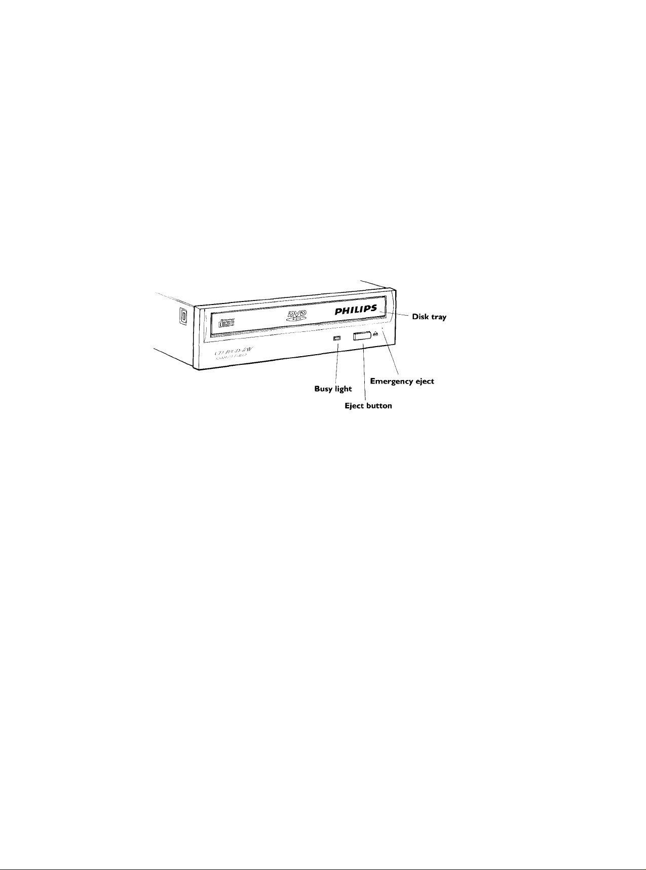
The DVD-ROM drive controls
Your DVD-ROM drive has the following features and controls:
• Disk tray
• Eject button
• Emergency Eject
• Busy light
The Eject Button
Pressing the Eject button opens the disk tray so you can put in or take out a disk.
Emergency Eject
You can still remove the disk from the drive even if the power supply to the DVD-ROM
drive fails. There is a small opening on the right of the front panel of the DVD-ROM drive.
Insert a pointed instrument (a straightened paper clip is ideal) into the opening and the disk
tray opens.
Operating the Disk Tray
Just press the Eject button to open the disk tray and remove or install your disk.
NOTE:
With desk-top computers never place drinks or other delicate objects
in front of the disk tray!
Loading a Disk
Put a disk into the tray of the DVD-ROM drive and gently push on the front of the open
disk tray. The tray automatically slides into the DVD-ROM drive.
Chapter S: Care and Use of Your DVD-ROM Drive 17
Page 20

Adit(ion;il ifvforTTiinion imilitbls jnour ^«Imice:
WWW. p<-be.phjij|3SrCtinT
S(>4clftci[«ns iub^a [0 without tidciee.
At dimEftiiHii. ihown arc approorimfitE.
(&l ?TB №il^i ElectnanKi N.V
All right? racrviid. ftcpf^g(cipn. wp^iPij UHfi,
(nadrijAr^,hiring,r«n[ln^ public p4rf4mnitnc4. [rAik(irK([lipi
jrid^ty brwlMiung In or |>srT I9 prohblMJ
Wlthourthfl WrUtEn COIiiAht of Phlp! Eltitroniii N.V
PrViMd hi Hit fiOEiiirtlridi
Thll imoull Im both pririUd -Ml piper.
 Loading...