

Philips PCA2000, PCA2001 Technical data

查询PCA2000供应商
INTEGRATED CIRCUITS
DATA SH EET
PCA2000; PCA2001
32 kHz watch circuit with
programmable adaptive motor
pulse
Product specification
Supersedes data of 2003 Feb 04
2003 Dec 17

Philips Semiconductors Product specification
32 kHz watch circuit with programmable
adaptive motor pulse
FEATURES
• Amplitude-regulated 32 kHz quartz crystal oscillator,
with excellent frequency stability and high immunity to
leakage currents
• Electrically programmable time calibration with 1 ppm
resolution stored in One Time Programmable (OTP)
memory
• The quartz crystal is the only external component
connected
• Very low power consumption, typical 90 nA
• One second output pulses for bipolar stepping motor
• Minimum power consumption for the entire watch, due
to self adaptation of the motor drive according to the
required torque
• Reliable step detection circuit
• Motor pulse width, pulse modulation, and pulse
adaptation rangeprogrammable in a wide range, stored
in OTP memory
• Stopfunction for accuratetimesetting and power saving
during shelf life
• End Of Life (EOL) indication for silver oxide or lithium
battery (only the PCA2000 has the EOL feature)
• Test mode for accelerated testing of the mechanical
parts and the IC.
PCA2000; PCA2001
GENERAL DESCRIPTION
The PCA2000; PCA2001 are CMOS integrated circuitsfor
battery operated wrist watches with a 32 kHz quartz
crystal as timing element and a bipolar 1 Hz stepping
motor. The quartz crystal oscillator and the frequency
divider are optimized for minimum power consumption.
A timing accuracy of 1 ppm is achieved with a
programmable, digital frequency adjustment.
To obtain the minimum overall power consumption for the
watch, an automatic motor pulse adaptation function is
provided. The circuit supplies only the minimum drive
current,which is necessarytoensure a correctmotor step.
Changing the drive current of the motor is achieved by
chopping the motor pulse with a variable duty cycle. The
pulsewidth and the range of the variable duty cycle can be
programmedtosuit different types of motor. Theautomatic
pulse adaptation scheme is based on a safe dynamic
detection of successful motor steps.
Apad RESET is provided(used for stoppingthe motor) for
accurate time setting and for accelerated testing of the
watch.
The PCA2000 has a battery EOL warning function. If the
battery voltage drops below the EOL threshold voltage
(which can be programmed for silver oxide or lithium
batteries), the motor steps change from one pulse per
second to a burst of four pulses every 4 seconds.
APPLICATIONS
• Driver circuits for bipolar stepping motors
• High immunity motor drive circuits.
ORDERING INFORMATION
TYPE NUMBER
NAME DESCRIPTION VERSION
PCA2000U/AA − bare die; chip in tray −
PCA2001U/AA − bare die; chip in tray −
PCA2000U/10AA − bare die; chip on film frame carrier −
PCA2001U/10AA − bare die; chip on film frame carrier −
The PCA2001 uses the same circuit as the PCA2000, but
without the EOL function.
PACKAGE
2003 Dec 17 2

Philips Semiconductors Product specification
32 kHz watch circuit with programmable
adaptive motor pulse
BLOCK DIAGRAM
DD
SS
3
4
5
1
2
OSCILLATOR
VOLTAGE DETECTOR,
OTP-CONTROLLER
÷4
TIMING ADJUSTMENT,
EOL
PCA2000 only
PCA2000
PCA2001
OSCIN
OSCOUT
V
V
TEST
8 kHz
INHIBITION
OTP-MEMORY
32 Hz
DIVIDER RESET
MOTOR CONTROL WITH
ADAPTIVE PULSE MODULATION
DETECTION
STEP
PCA2000; PCA2001
8
RESET
reset
1 Hz
PINNING
SYMBOL PAD DESCRIPTION
V
SS
1 ground
TEST 2 test output
OSCIN 3 oscillator input
OSCOUT 4 oscillator output
V
DD
5 supply voltage
MOT1 6 motor 1 output
MOT2 7 motor 2 output
RESET 8 reset input
67
Fig.1 Block diagram.
handbook, halfpage
OSCOUT
V
SS
TEST
OSCIN
mgw567
MOT2MOT1
1
2
8
7
PCA2000
PCA2001
3
4
6
5
MGU554
Fig.2 Pad configuration.
RESET
MOT2
MOT1
V
DD
2003 Dec 17 3

Philips Semiconductors Product specification
32 kHz watch circuit with programmable
adaptive motor pulse
FUNCTIONAL DESCRIPTION
Motor pulse
The motor output supplies pulses of different driving
stages, depending on the torque required to turn on the
motor. The number of different stages can be selected
between three and six. With the exception of the highest
driving stage, each motor pulse (tp in Figs 3 and 6) is
followed by a detection phase during which the motor
movement is monitored, in order to check whether the
motor has turned correctly or not.
If a missing step is detected, a correction sequence is
generated (see Fig.3) and the driving stage is switched to
the next level. The correction sequence consists of two
pulses: first a short pulse in the opposite direction
(0.98 ms, modulated withthe maximumduty cycle) to give
the motor a defined position, followed by a motor pulse of
the strongest driving level. Every 4 minutes, the driving
level is lowered again by one stage.
The motor pulse has a constant pulse width. The driving
level is regulated by chopping the driving pulse with a
variable duty cycle. The driving level starts from the
programmedminimumvalue and increases by6.25%after
each failed motor step. The strongest driving stage, which
is not followed by a detection phase, is programmed
separately.
PCA2000; PCA2001
Therefore, it is possible to program a larger energy gap
between the pulses with step detection and the strongest,
not monitored, pulse. This might be necessary to ensure a
reliable and stable operation under adverse conditions
(magnetic fields, vibrations). If the watch works in the
highest driving stage, the driving level jumps after the
4-minute period directly to the lowest stage, and not just
one stage lower.
To optimize the performance for different motors, the
following parameters can be programmed:
• Pulse width: 0.98 to 7.8 ms in steps of 0.98 ms
• Duty cycle of lowest driving level: 37.5% to 56.25% in
steps of 6.25%
• Number of driving levels (including the highest driving
level): 3 to 6
• Duty cycle of the highest driving level: 75% or 100%
• Enlargement pulse forthe highestdriving level: on or off.
The enlargement pulse has a duty cycle of 25% and a
pulse width which is twice the programmed motor pulse
width. The repetition period for the chopping pattern is
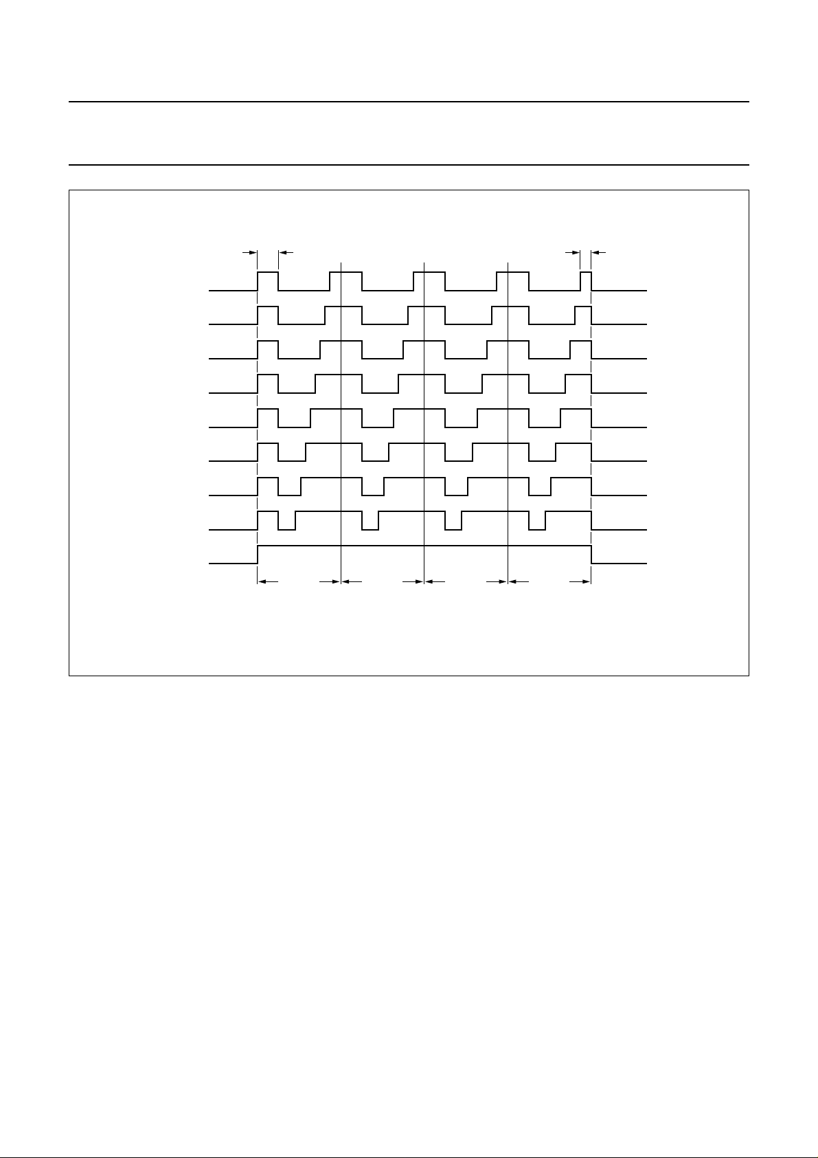
0.98 ms. Figure 4 shows an example of a 3.9 ms pulse.
handbook, full pagewidth
1.96 ms
t
p
detection phase
31.25 ms
0.98 ms
31.25 ms
Fig.3 Correction sequence after failed motor step.
2003 Dec 17 4
t
p
2t
p
MGW350
Philips Semiconductors Product specification
32 kHz watch circuit with programmable
adaptive motor pulse
handbook, full pagewidth
DUTY CYCLE
37.5%
43.75%
50%
56.25%
62.5%
68.75%
75%
81.25%
0.244 ms 0.122 ms
PCA2000; PCA2001
100%
Fig.4 Possible modulations for a 3.9 ms motor pulse.
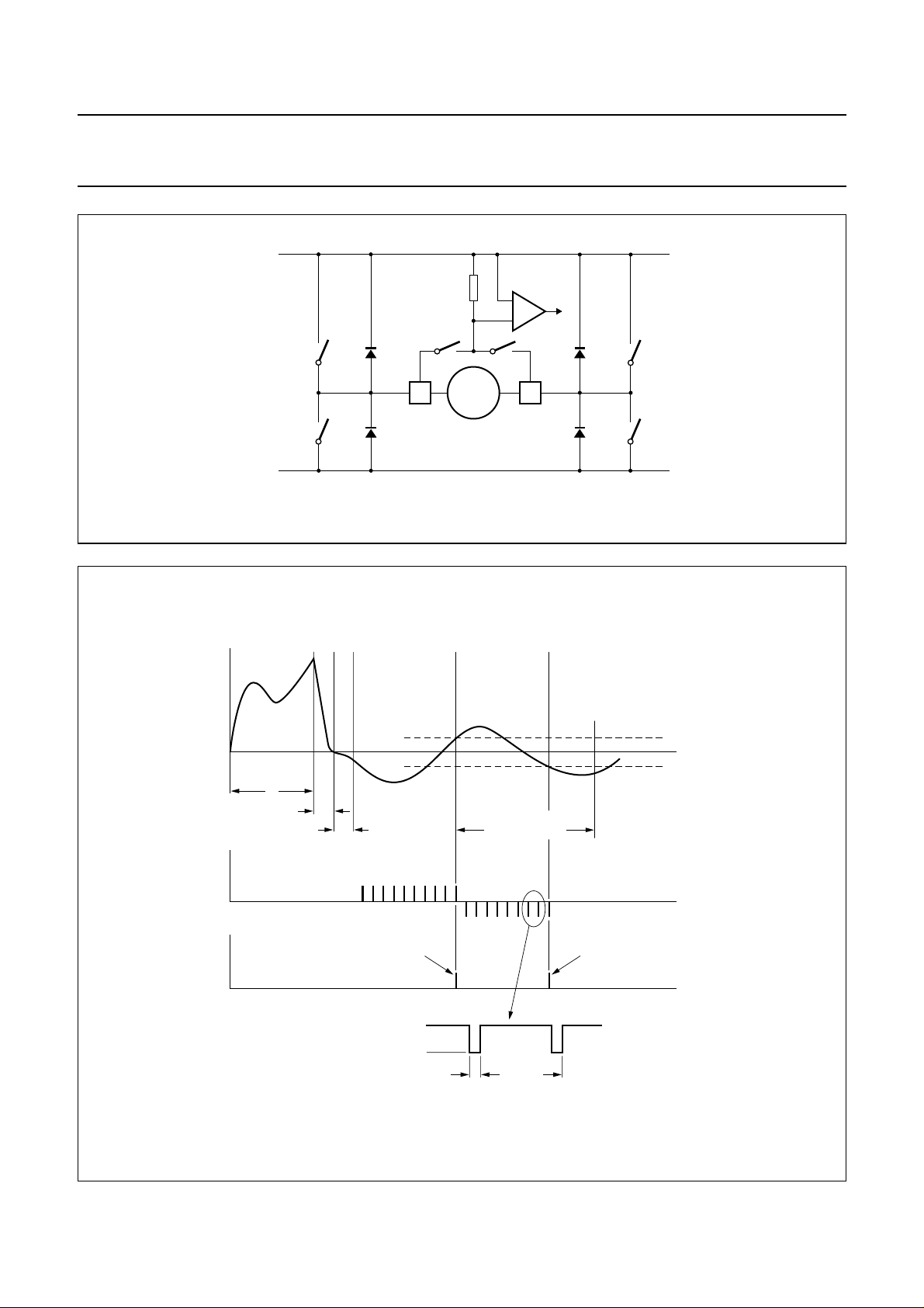
Step detection
Figure 5 shows a simplified diagram of the motor driving
and step detection circuit, and Fig.6 shows the step
detection sequence and corresponding sampling current.
Betweenthe motor driving pulses,theswitches P1 and P2
are closed, which means the motor is short-circuited. For
a pulse in one direction, P1 and N2 are open, and
P2 and N1 are closed with the appropriate duty cycle; for
a pulse inthe opposite direction, P2 and N1 are open, and
P1 and N2 closed.
Thestep detection phaseisinitiated after themotor driving
pulse (see Fig.3). P1 and P2 are first closed for 0.98 ms
and then all four drive switches (P1, N1, P2 and N2) are
opened for 0.98 ms.
As a result, the energy stored in the motor inductance is
reduced as fast as possible.
0.98 ms0.98 ms0.98 ms 0.98 ms
MGW351
The induced current caused by the residual motor
movement is thensampled in phase 3(closing P3 and P2)
and in phase 4 (closing P1 and P4). For step detection in
the opposite direction P1 and P4 are closed during
phase 3 and P2 and P3 during phase 4 (see Fig.6).
The condition fora successful motorstep is a positive step
detection pulse (current in the same direction as in the
driving phase) followed by a negative detection pulse
withinagiven time limit. This timelimitcanbeprogrammed
between 3.9 and 10.7 ms (in steps of 0.98 ms) in order to
ensure a safe and correct step detection under all
conditions (for instance magnetic fields). The step
detection phase stops after the last 31.25 ms, after the
start of the motor driving pulse.
2003 Dec 17 5
Philips Semiconductors Product specification
32 kHz watch circuit with programmable
adaptive motor pulse
V
handbook, full pagewidth
DD
P1
MOT1
N1
V
SS
Fig.5 Simplified diagram of motor driving and step detection circuit.
R
D
MOTOR
PCA2000; PCA2001
D1
P4P3
MOT2
P2
N2
MGW352
handbook, full pagewidth
I
MOT
sampling
voltage
sampling
voltage
t
p
0.98 ms
(motor shorted)
sampling results
phase 1
phase 2
positive detection
motor shorted
phase 3
td = 0.98 ms
sampling
sampling
61 µs
phase 4
programmable time limit
OTP C4 to C6
negative detection
0.49 ms
positive detection level
t
negative detection level
t
t
MGW569
Fig.6 Step detection sequence and corresponding sampling voltage.
2003 Dec 17 6
 Loading...