

Philips pca167x DATASHEETS

INTEGRATED CIRCUITS
DATA SH EET
PCA167x series
32 kHz watch circuits using a
silver-oxide or a 3 V lithium battery
Product specification
Supersedes data of 1997 Apr 22
File under Integrated Circuits, IC16
1998 Apr 03
Philips Semiconductors Product specification
32 kHz watch circuits using a silver-oxide
PCA167x series
or a 3 V lithium battery
FEATURES
• 32 kHz oscillator, amplitude regulated with excellent
frequency stability
• High immunity of the oscillator to leakage currents
• Very low current consumption; typically 150 nA
• Stop function for accurate timing
• Chopped motor pulses available
• Power-on reset for fast testing
• Various test modes for testing the mechanical parts of
the watch and the IC.
ORDERING INFORMATION
TYPE
NUMBER
NAME DESCRIPTION VERSION
PCA1672U − chip in tray −
PCA1673U − chip in tray −
PCA1675U − chip in tray −
PCA1676U/10 − chip on foil −
PCA1677U − chip in tray −
GENERAL DESCRIPTION
The PCA167x series devices are CMOS integrated circuits
specially suited for battery-operated,
quartz-crystal-controlled wrist-watches, with a bipolar
stepping motor.
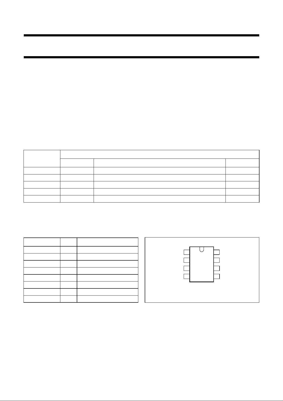
PACKAGE
(1)
Note
1. Figure 1 and Chapter “Package outline” show details of standard package, available for large orders only.
Chapter “Chip dimensions and bonding pad locations” shows exact pad locations for other delivery formats.
PINNING
SYMBOL PIN DESCRIPTION
V
SS
TEST 2 test output
OSC IN 3 oscillator input
OSC OUT 4 oscillator output
V
DD
M1 6 motor 1 output
M2 7 motor 2 output
1 ground (0 V)
5 positive supply voltage
V
SS
TEST
OSC IN
OSC OUT
1
2
PCA167xT
3
4
MSA978
8
7
6
5
RESET
M2
M1
V
DD
Fig.1 Pin configuration, PCA167xT, (PMFP8).
RESET 8 reset input
1998 Apr 03 2
Philips Semiconductors Product specification
32 kHz watch circuits using a silver-oxide
PCA167x series
or a 3 V lithium battery
FUNCTIONAL DESCRIPTION AND TESTING
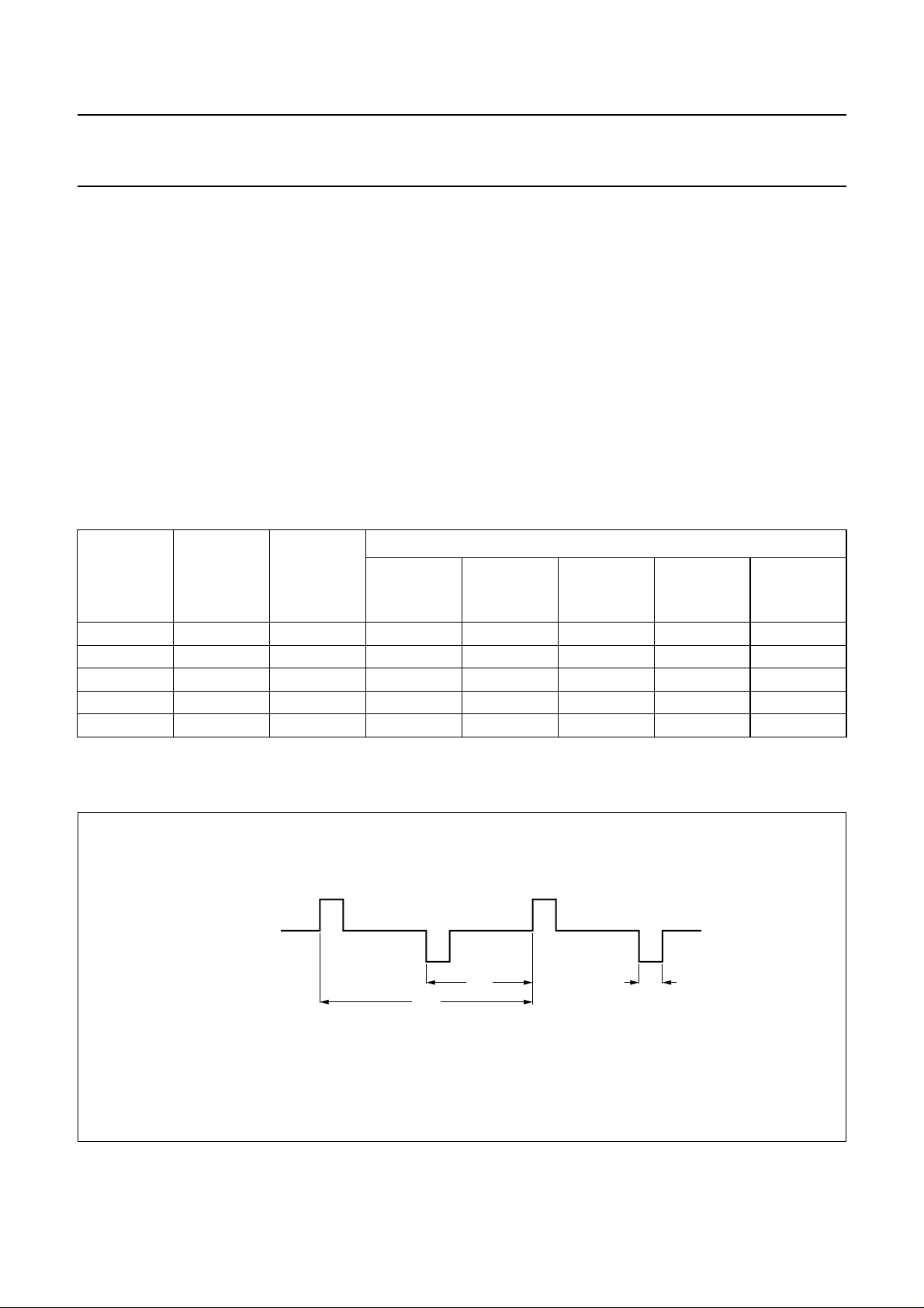
Motor pulse
The motor output pulse widths (t
) and the cycle times (tT)
P
are given in Chapter “Available types”.
Power-on reset
For correct operation of the Power-on reset the rise time of
from 0 V to 1.55 V should be less than 0.1 ms.
V
DD
All resettable flip-flops are reset. Additionally the polarity of
the first motor pulse is positive: VM1− VM2≥ 0V.
AVAILABLE TYPES
Refer to Fig.2 and to Chapters “Ordering information” and “Functional description and testing”.
(1)
PERIOD
t
T
(s)
PULSE
WIDTH t
SHORT
TYPE
NUMBER
DELIVERY
FORMAT
(ms)
1672 U 1 7.8 56 no no 3 V Lithium
1673 U 1 5.8 56 no no 3 V Lithium
1675 U 1/16 5.8 100 no no no oscillator
1676 U/10 10 5.8 56 no no 3 V Lithium
1677 U 10 7.8 100 no no 1.5 V
Customer testing and stop mode
An output frequency of 32 Hz is provided at RESET (pin 8)
to be used for exact frequency measurement.
Connecting the RESET to V
stops the motor pulses
DD
leaving them in a HIGH impedance 3-state condition and a
32 Hz signal is produced at the TEST pin. A debounce
circuit protects against accidental stoppages due to
mechanical shock to the watch (t
= 14.7 to 123.2 ms).
DEB
Connecting RESET to VSS activates the test mode.
The motor pulse period is 31.25 ms instead of tT. Test and
stop mode are disabled by disconnecting RESET
(open-circuit).
SPECIFICATIONS
P
DRIVE
(%)
EEPROM
BATTERY
EOL
DETECTION
REMARKS
Note
1. U = Chip in trays; U/10 = chip on foil.
V
M1 - M2
Fig.2 Motor output waveform (normal operation).
t
T
2t
T
MSA977
t
P
1998 Apr 03 3
Philips Semiconductors Product specification
32 kHz watch circuits using a silver-oxide
PCA167x series
or a 3 V lithium battery
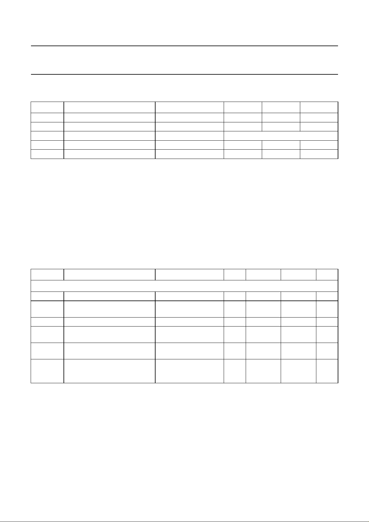
LIMITING VALUES
In accordance with the Absolute Maximum Rating System (IEC 134).
SYMBOL PARAMETER CONDITIONS MIN. MAX. UNIT
V
DD
V
I
T
amb
T
stg
Note
1. Connecting the battery with reversed polarity does not destroy the circuit, but in this condition a large current flows,
which will rapidly discharge the battery.
HANDLING
Inputs and outputs are protected against electrostatic discharges in normal handling. However, to be totally safe, it is
advisable to take handling precautions appropriate to handling MOS devices. Advice can be found in
“Data Handbook IC16, General, Handling MOS Devices”
supply voltage VSS= 0 V; note 1 −1.8 +6 V
all input voltages V
SS
V
DD
V
output short-circuit duration indefinite
operating ambient temperature −10 +60 °C
storage temperature −30 +100 °C
.
CHARACTERISTICS
= 1.55 V; VSS=0V; f
V
DD
= 1 to 3 pF; unless otherwise specified.
C
0
= 32.768 kHz; T
osc
=25°C; crystal: RS=20kΩ; C1= 2 to 3 fF; CL= 8 to 10 pF;
amb
SYMBOL PARAMETER CONDITIONS MIN. TYP. MAX. UNIT
Supply
V
∆V
DD
DD
supply voltage T
supply voltage variation transient;
= −10 to +60 °C 1.2 1.5 3.5 V
amb
−− 0.25 V
VDD= 1.2 to 3.5 V
I
DD1
I
DD2
supply current between motor pulses − 150 250 nA
supply current between motor pulses;
− 200 350 nA
VDD= 3.5 V
I
DD3
I
DD4
supply current stop mode; pin 8
connected to V
supply current stop mode; pin 8
− 180 300 nA
DD
− 300 480 nA
connected to VDD;
VDD= 3.5 V
1998 Apr 03 4
 Loading...